4WD DODGE RAM 2001 Service Repair Manual
[x] Cancel search | Manufacturer: DODGE, Model Year: 2001, Model line: RAM, Model: DODGE RAM 2001Pages: 2889, PDF Size: 68.07 MB
Page 19 of 2889
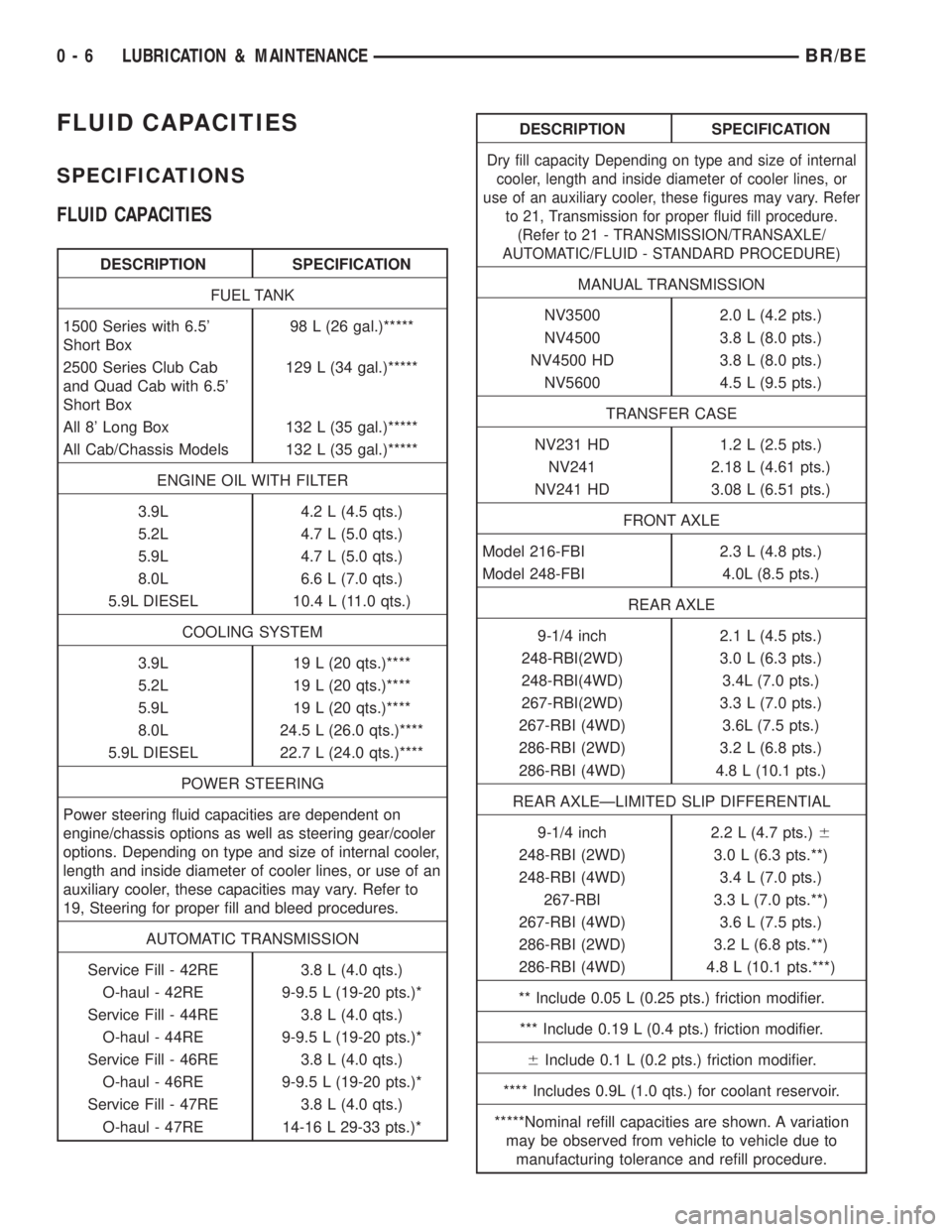
FLUID CAPACITIES
SPECIFICATIONS
FLUID CAPACITIES
DESCRIPTION SPECIFICATION
FUEL TANK
1500 Series with 6.5'
Short Box98 L (26 gal.)*****
2500 Series Club Cab
and Quad Cab with 6.5'
Short Box129 L (34 gal.)*****
All 8' Long Box 132 L (35 gal.)*****
All Cab/Chassis Models 132 L (35 gal.)*****
ENGINE OIL WITH FILTER
3.9L 4.2 L (4.5 qts.)
5.2L 4.7 L (5.0 qts.)
5.9L 4.7 L (5.0 qts.)
8.0L 6.6 L (7.0 qts.)
5.9L DIESEL 10.4 L (11.0 qts.)
COOLING SYSTEM
3.9L 19 L (20 qts.)****
5.2L 19 L (20 qts.)****
5.9L 19 L (20 qts.)****
8.0L 24.5 L (26.0 qts.)****
5.9L DIESEL 22.7 L (24.0 qts.)****
POWER STEERING
Power steering fluid capacities are dependent on
engine/chassis options as well as steering gear/cooler
options. Depending on type and size of internal cooler,
length and inside diameter of cooler lines, or use of an
auxiliary cooler, these capacities may vary. Refer to
19, Steering for proper fill and bleed procedures.
AUTOMATIC TRANSMISSION
Service Fill - 42RE 3.8 L (4.0 qts.)
O-haul - 42RE 9-9.5 L (19-20 pts.)*
Service Fill - 44RE 3.8 L (4.0 qts.)
O-haul - 44RE 9-9.5 L (19-20 pts.)*
Service Fill - 46RE 3.8 L (4.0 qts.)
O-haul - 46RE 9-9.5 L (19-20 pts.)*
Service Fill - 47RE 3.8 L (4.0 qts.)
O-haul - 47RE 14-16 L 29-33 pts.)*
DESCRIPTION SPECIFICATION
Dry fill capacity Depending on type and size of internal
cooler, length and inside diameter of cooler lines, or
use of an auxiliary cooler, these figures may vary. Refer
to 21, Transmission for proper fluid fill procedure.
(Refer to 21 - TRANSMISSION/TRANSAXLE/
AUTOMATIC/FLUID - STANDARD PROCEDURE)
MANUAL TRANSMISSION
NV3500 2.0 L (4.2 pts.)
NV4500 3.8 L (8.0 pts.)
NV4500 HD 3.8 L (8.0 pts.)
NV5600 4.5 L (9.5 pts.)
TRANSFER CASE
NV231 HD 1.2 L (2.5 pts.)
NV241 2.18 L (4.61 pts.)
NV241 HD 3.08 L (6.51 pts.)
FRONT AXLE
Model 216-FBI 2.3 L (4.8 pts.)
Model 248-FBI 4.0L (8.5 pts.)
REAR AXLE
9-1/4 inch 2.1 L (4.5 pts.)
248-RBI(2WD) 3.0 L (6.3 pts.)
248-RBI(4WD) 3.4L (7.0 pts.)
267-RBI(2WD) 3.3 L (7.0 pts.)
267-RBI (4WD) 3.6L (7.5 pts.)
286-RBI (2WD) 3.2 L (6.8 pts.)
286-RBI (4WD) 4.8 L (10.1 pts.)
REAR AXLEÐLIMITED SLIP DIFFERENTIAL
9-1/4 inch 2.2 L (4.7 pts.)6
248-RBI (2WD) 3.0 L (6.3 pts.**)
248-RBI (4WD) 3.4 L (7.0 pts.)
267-RBI 3.3 L (7.0 pts.**)
267-RBI (4WD) 3.6 L (7.5 pts.)
286-RBI (2WD) 3.2 L (6.8 pts.**)
286-RBI (4WD) 4.8 L (10.1 pts.***)
** Include 0.05 L (0.25 pts.) friction modifier.
*** Include 0.19 L (0.4 pts.) friction modifier.
6Include 0.1 L (0.2 pts.) friction modifier.
**** Includes 0.9L (1.0 qts.) for coolant reservoir.
*****Nominal refill capacities are shown. A variation
may be observed from vehicle to vehicle due to
manufacturing tolerance and refill procedure.
0 - 6 LUBRICATION & MAINTENANCEBR/BE
Page 42 of 2889
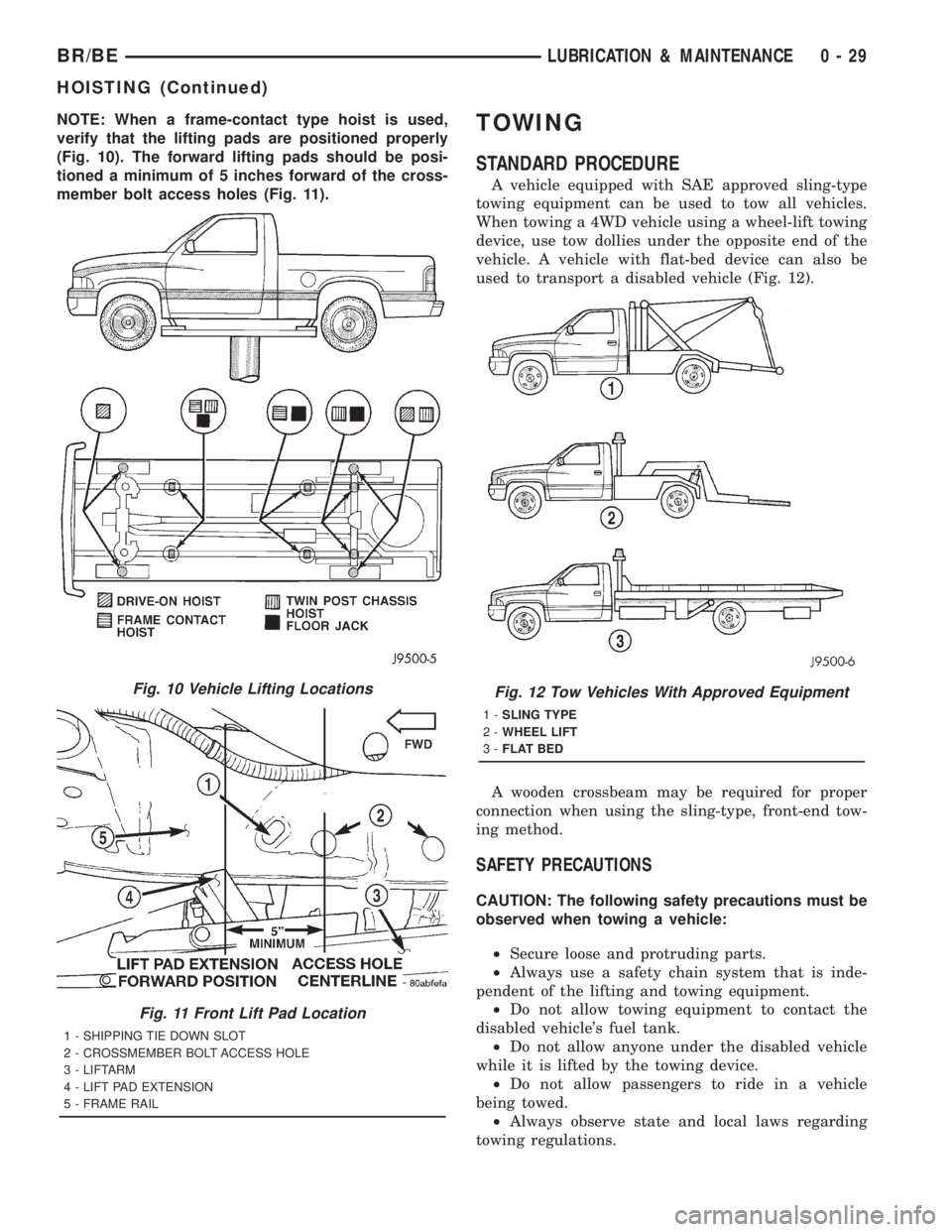
NOTE: When a frame-contact type hoist is used,
verify that the lifting pads are positioned properly
(Fig. 10). The forward lifting pads should be posi-
tioned a minimum of 5 inches forward of the cross-
member bolt access holes (Fig. 11).TOWING
STANDARD PROCEDURE
A vehicle equipped with SAE approved sling-type
towing equipment can be used to tow all vehicles.
When towing a 4WD vehicle using a wheel-lift towing
device, use tow dollies under the opposite end of the
vehicle. A vehicle with flat-bed device can also be
used to transport a disabled vehicle (Fig. 12).
A wooden crossbeam may be required for proper
connection when using the sling-type, front-end tow-
ing method.
SAFETY PRECAUTIONS
CAUTION: The following safety precautions must be
observed when towing a vehicle:
²Secure loose and protruding parts.
²Always use a safety chain system that is inde-
pendent of the lifting and towing equipment.
²Do not allow towing equipment to contact the
disabled vehicle's fuel tank.
²Do not allow anyone under the disabled vehicle
while it is lifted by the towing device.
²Do not allow passengers to ride in a vehicle
being towed.
²Always observe state and local laws regarding
towing regulations.
Fig. 10 Vehicle Lifting Locations
Fig. 11 Front Lift Pad Location
1 - SHIPPING TIE DOWN SLOT
2 - CROSSMEMBER BOLT ACCESS HOLE
3 - LIFTARM
4 - LIFT PAD EXTENSION
5 - FRAME RAIL
Fig. 12 Tow Vehicles With Approved Equipment
1-SLING TYPE
2-WHEEL LIFT
3-FLAT BED
BR/BELUBRICATION & MAINTENANCE 0 - 29
HOISTING (Continued)
Page 43 of 2889
²Do not tow a vehicle in a manner that could
jeopardize the safety of the operator, pedestrians or
other motorists.
²Do not attach tow chains, T-hooks, J-hooks, or a
tow sling to a bumper, steering linkage, drive shafts
or a non-reinforced frame hole.
²Do not tow a heavily loaded vehicle. Damage to
the cab, cargo box or frame may result. Use a flatbed
device to transport a loaded vehicle.
GROUND CLEARANCE
CAUTION: If vehicle is towed with wheels removed,
install lug nuts to retain brake drums or rotors.
A towed vehicle should be raised until lifted wheels
are a minimum 100 mm (4 in) from the ground. Be
sure there is adequate ground clearance at the oppo-
site end of the vehicle, especially when towing over
rough terrain or steep rises in the road. If necessary,
remove the wheels from the lifted end of the vehicle
and lower the vehicle closer to the ground, to
increase the ground clearance at the opposite end of
the vehicle. Install lug nuts on wheel attaching studs
to retain brake drums or rotors.
RAMP ANGLE
If a vehicle with flat-bed towing equipment is used,
the approach ramp angle should not exceed 15
degrees.
TOWING WHEN KEYS ARE NOT AVAILABLE
When the vehicle is locked and keys are not avail-
able, use a flat bed hauler. A Wheel-lift or Sling-type
device can be used on 4WD vehicles providedall the
wheels are lifted off the ground using tow dol-
lies.
FOUR-WHEEL-DRIVE VEHICLE TOWING
Chrysler Corporation recommends that a vehicle be
transported on a flat-bed device. A Wheel-lift or
Sling-type device can be used providedall the
wheels are lifted off the ground using tow dol-
lies.
WARNING: WHEN TOWING A DISABLED VEHICLE
AND THE DRIVE WHEELS ARE SECURED IN A
WHEEL LIFT OR TOW DOLLIES, ENSURE THE
TRANSMISSION IS IN THE PARK POSITION (AUTO-
MATIC TRANSMISSION) OR A FORWARD DRIVE
GEAR (MANUAL TRANSMISSION).
CAUTION: Many vehicles are equipped with air
dams, spoilers, and/or ground effect panels. To
avoid component damage, a wheel-lift towing vehi-
cle or a flat-bed hauling vehicle is recommended.
0 - 30 LUBRICATION & MAINTENANCEBR/BE
TOWING (Continued)
Page 44 of 2889
SUSPENSION
TABLE OF CONTENTS
page page
WHEEL ALIGNMENT.......................1
FRONT - 2WD............................7FRONT - 4WD...........................14
REAR..................................26
WHEEL ALIGNMENT
TABLE OF CONTENTS
page page
WHEEL ALIGNMENT
DESCRIPTION............................1
OPERATION.............................2
DIAGNOSIS AND TESTING..................2
PRE-ALIGNMENT........................2
STANDARD PROCEDURE...................2ALIGNMENT INDEPENDENT FRONT
SUSPENSION...........................2
CASTER CORRECTION MEASUREMENT.....3
ALIGNMENT LINK/COIL SUSPENSION........5
SPECIFICATIONS.........................6
WHEEL ALIGNMENT
DESCRIPTION
Wheel alignment is the positioning of the wheels in
relation to the vehicle. This is accomplished through
suspension and steering linkage adjustments. An
alignment is essential for efficient steering, good
directional stability and to minimize tire wear. The
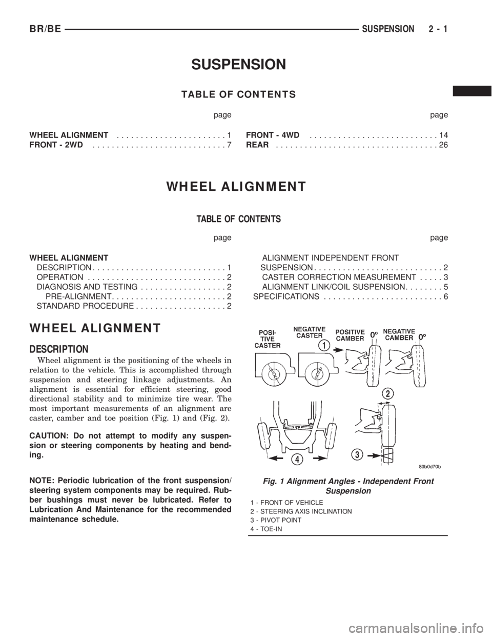
most important measurements of an alignment are
caster, camber and toe position (Fig. 1) and (Fig. 2).
CAUTION: Do not attempt to modify any suspen-
sion or steering components by heating and bend-
ing.
NOTE: Periodic lubrication of the front suspension/
steering system components may be required. Rub-
ber bushings must never be lubricated. Refer to
Lubrication And Maintenance for the recommended
maintenance schedule.
Fig. 1 Alignment Angles - Independent Front
Suspension
1 - FRONT OF VEHICLE
2 - STEERING AXIS INCLINATION
3 - PIVOT POINT
4 - TOE-IN
BR/BESUSPENSION 2 - 1
Page 57 of 2889
FRONT - 4WD
TABLE OF CONTENTS
page page
FRONT - 4WD
DESCRIPTION...........................14
SPECIFICATIONS........................15
SPECIAL TOOLS.........................16
HUB / BEARING
REMOVAL..............................16
INSTALLATION...........................18
KNUCKLE
DESCRIPTION...........................20
OPERATION.............................20
REMOVAL..............................20
INSTALLATION...........................20
LOWER CONTROL ARM
REMOVAL..............................20
INSTALLATION...........................20
SHOCK
DESCRIPTION...........................21
OPERATION.............................21
DIAGNOSIS AND TESTING.................21
SHOCK..............................21
REMOVAL..............................21
INSTALLATION...........................21
SPRING
DESCRIPTION...........................22OPERATION.............................22
REMOVAL..............................22
INSTALLATION...........................22
STABILIZER BAR
DESCRIPTION...........................22
OPERATION.............................22
REMOVAL..............................22
INSTALLATION...........................23
TRACK BAR
DESCRIPTION...........................23
OPERATION.............................23
DIAGNOSIS AND TESTING.................23
TRACK BAR...........................23
REMOVAL..............................23
INSTALLATION...........................23
UPPER CONTROL ARM
REMOVAL..............................23
INSTALLATION...........................24
LOWER BALL JOINT
REMOVAL..............................24
INSTALLATION...........................25
UPPER BALL JOINT
REMOVAL..............................25
INSTALLATION...........................25
FRONT - 4WD
DESCRIPTION
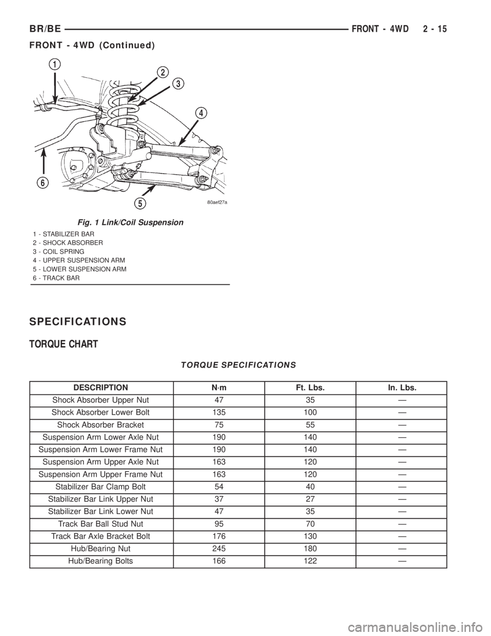
The link/coil suspension allows each wheel to adapt
to different road surfaces. The suspension is com-
prised of (Fig. 1) :
²Shock absorbers
²Coil springs
²Upper and lower suspension arms
²Stabilizer bar
²Track bar
²Steering Knuckles
²Hub/Bearing
²Ball Joints
²Jounce Bumpers
CAUTION: Components attached with a nut and cot-
ter pin must be torqued to specification. Then if the
slot in the nut does not line up with the cotter pin
hole, tighten nut until it is aligned. Never loosen the
nut to align the cotter pin hole.CAUTION: Suspension components with rubber
bushings (except stabilizer bar) should be tightened
with the vehicle at normal height. It is important to
have the springs supporting the weight of the vehi-
cle when the fasteners are torqued. If springs are
not at their normal ride position, vehicle ride com-
fort could be affected and premature bushing wear
may occur.
DESCRIPTION
The upper and lower suspension arms use bush-
ings to isolate road noise. The suspension arms are
bolted to the frame and axle through the rubber
bushings. The lower suspension arm uses cam bolts
at the axle to allow for caster and pinion angle
adjustment.
2 - 14 FRONT - 4WDBR/BE
Page 58 of 2889
SPECIFICATIONS
TORQUE CHART
TORQUE SPECIFICATIONS
DESCRIPTION N´m Ft. Lbs. In. Lbs.
Shock Absorber Upper Nut 47 35 Ð
Shock Absorber Lower Bolt 135 100 Ð
Shock Absorber Bracket 75 55 Ð
Suspension Arm Lower Axle Nut 190 140 Ð
Suspension Arm Lower Frame Nut 190 140 Ð
Suspension Arm Upper Axle Nut 163 120 Ð
Suspension Arm Upper Frame Nut 163 120 Ð
Stabilizer Bar Clamp Bolt 54 40 Ð
Stabilizer Bar Link Upper Nut 37 27 Ð
Stabilizer Bar Link Lower Nut 47 35 Ð
Track Bar Ball Stud Nut 95 70 Ð
Track Bar Axle Bracket Bolt 176 130 Ð
Hub/Bearing Nut 245 180 Ð
Hub/Bearing Bolts 166 122 Ð
Fig. 1 Link/Coil Suspension
1 - STABILIZER BAR
2 - SHOCK ABSORBER
3 - COIL SPRING
4 - UPPER SUSPENSION ARM
5 - LOWER SUSPENSION ARM
6 - TRACK BAR
BR/BEFRONT - 4WD 2 - 15
FRONT - 4WD (Continued)
Page 59 of 2889
SPECIAL TOOLS
LINK/COIL SUSPENSION
HUB / BEARING
REMOVAL - 2500/3500
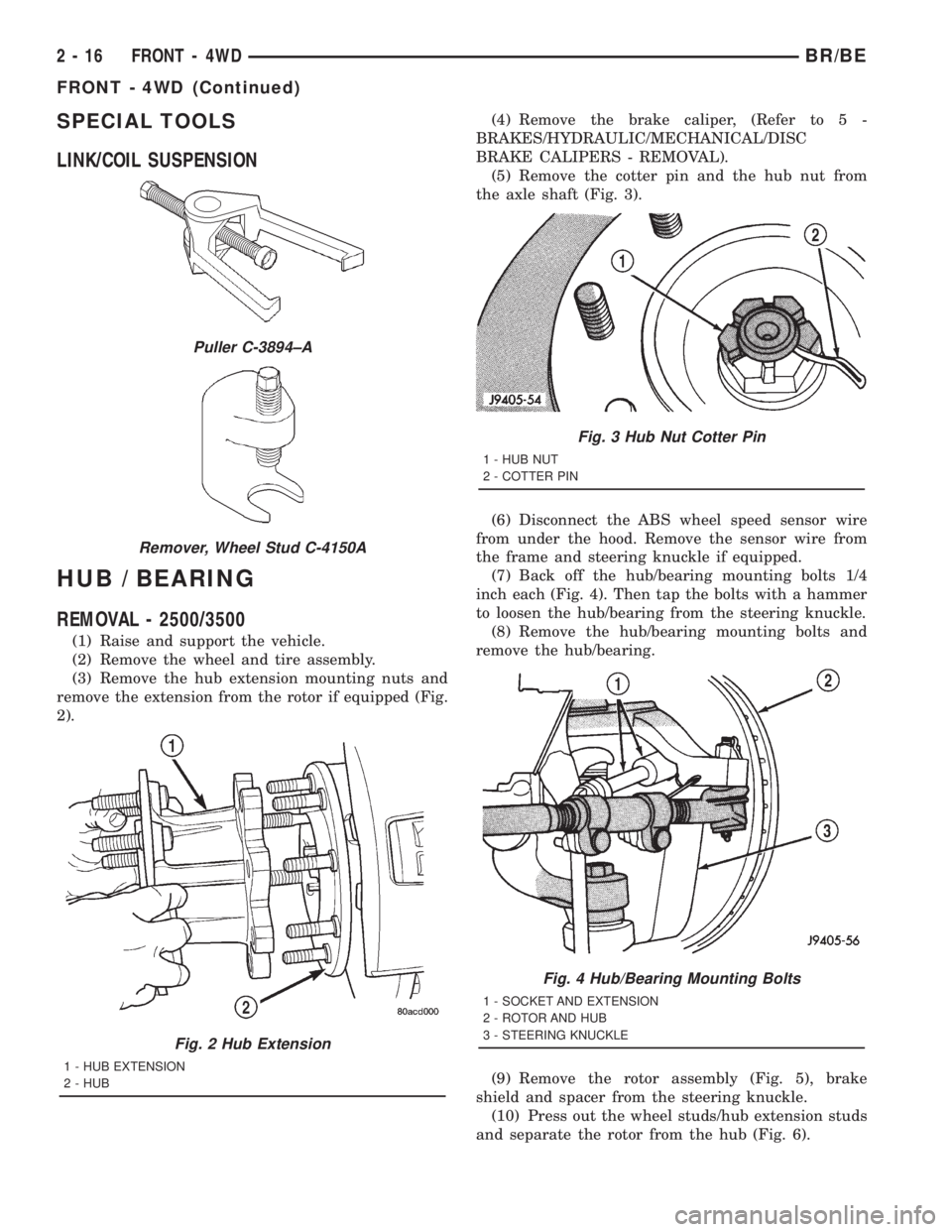
(1) Raise and support the vehicle.
(2) Remove the wheel and tire assembly.
(3) Remove the hub extension mounting nuts and
remove the extension from the rotor if equipped (Fig.
2).(4) Remove the brake caliper, (Refer to 5 -
BRAKES/HYDRAULIC/MECHANICAL/DISC
BRAKE CALIPERS - REMOVAL).
(5) Remove the cotter pin and the hub nut from
the axle shaft (Fig. 3).
(6) Disconnect the ABS wheel speed sensor wire
from under the hood. Remove the sensor wire from
the frame and steering knuckle if equipped.
(7) Back off the hub/bearing mounting bolts 1/4
inch each (Fig. 4). Then tap the bolts with a hammer
to loosen the hub/bearing from the steering knuckle.
(8) Remove the hub/bearing mounting bolts and
remove the hub/bearing.
(9) Remove the rotor assembly (Fig. 5), brake
shield and spacer from the steering knuckle.
(10) Press out the wheel studs/hub extension studs
and separate the rotor from the hub (Fig. 6).
Puller C-3894±A
Remover, Wheel Stud C-4150A
Fig. 2 Hub Extension
1 - HUB EXTENSION
2 - HUB
Fig. 3 Hub Nut Cotter Pin
1 - HUB NUT
2 - COTTER PIN
Fig. 4 Hub/Bearing Mounting Bolts
1 - SOCKET AND EXTENSION
2 - ROTOR AND HUB
3 - STEERING KNUCKLE
2 - 16 FRONT - 4WDBR/BE
FRONT - 4WD (Continued)
Page 60 of 2889
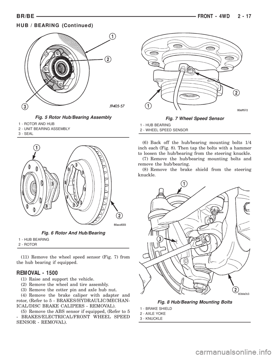
(11) Remove the wheel speed sensor (Fig. 7) from
the hub bearing if equipped.
REMOVAL - 1500
(1) Raise and support the vehicle.
(2) Remove the wheel and tire assembly.
(3) Remove the cotter pin and axle hub nut.
(4) Remove the brake caliper with adapter and
rotor, (Refer to 5 - BRAKES/HYDRAULIC/MECHAN-
ICAL/DISC BRAKE CALIPERS - REMOVAL).
(5) Remove the ABS sensor if equipped, (Refer to 5
- BRAKES/ELECTRICAL/FRONT WHEEL SPEED
SENSOR - REMOVAL).(6) Back off the hub/bearing mounting bolts 1/4
inch each (Fig. 8). Then tap the bolts with a hammer
to loosen the hub/bearing from the steering knuckle.
(7) Remove the hub/bearing mounting bolts and
remove the hub/bearing.
(8) Remove the brake shield from the steering
knuckle.
Fig. 5 Rotor Hub/Bearing Assembly
1 - ROTOR AND HUB
2 - UNIT BEARING ASSEMBLY
3 - SEAL
Fig. 6 Rotor And Hub/Bearing
1 - HUB BEARING
2 - ROTOR
Fig. 7 Wheel Speed Sensor
1 - HUB BEARING
2 - WHEEL SPEED SENSOR
Fig. 8 Hub/Bearing Mounting Bolts
1 - BRAKE SHIELD
2 - AXLE YOKE
3 - KNUCKLE
BR/BEFRONT - 4WD 2 - 17
HUB / BEARING (Continued)
Page 61 of 2889
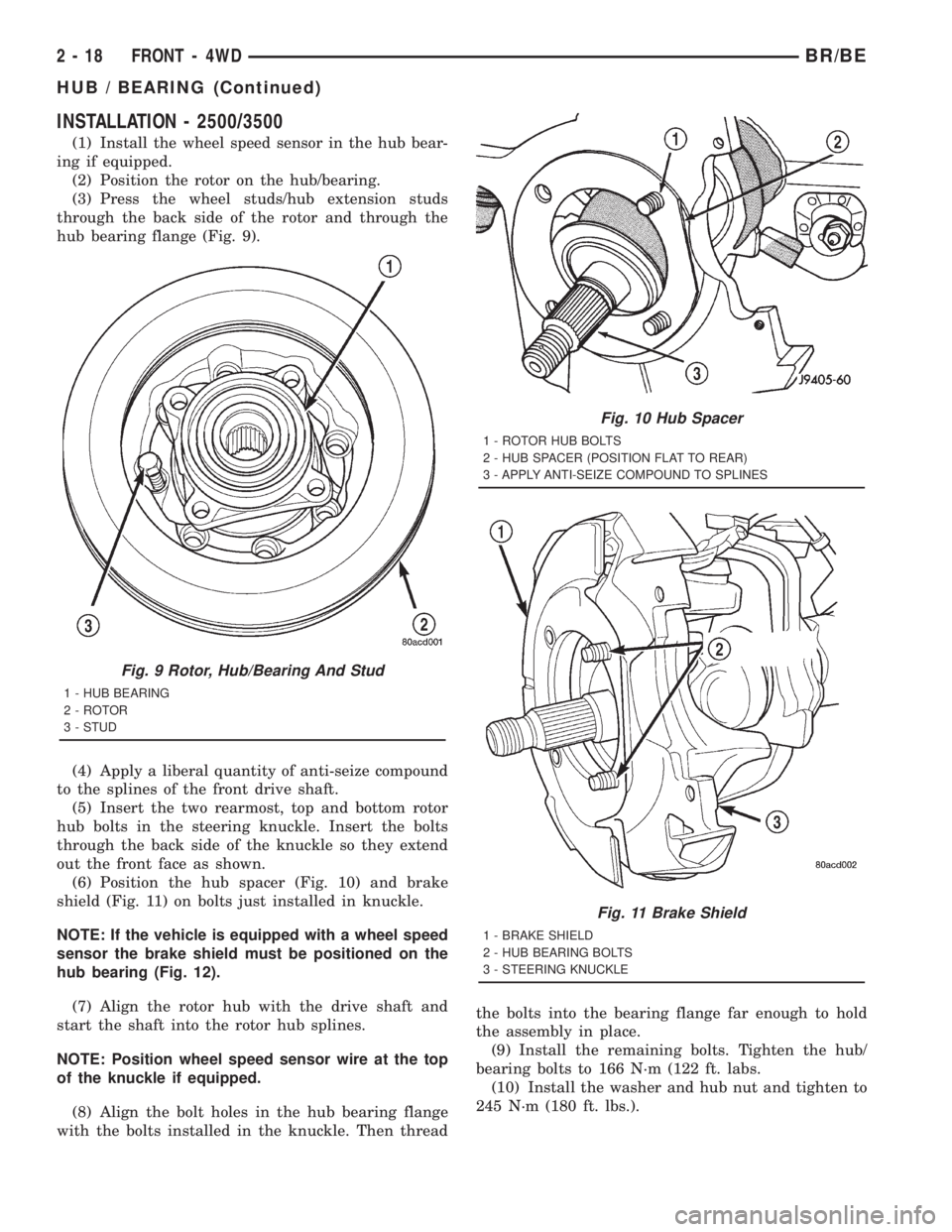
INSTALLATION - 2500/3500
(1) Install the wheel speed sensor in the hub bear-
ing if equipped.
(2) Position the rotor on the hub/bearing.
(3) Press the wheel studs/hub extension studs
through the back side of the rotor and through the
hub bearing flange (Fig. 9).
(4) Apply a liberal quantity of anti-seize compound
to the splines of the front drive shaft.
(5) Insert the two rearmost, top and bottom rotor
hub bolts in the steering knuckle. Insert the bolts
through the back side of the knuckle so they extend
out the front face as shown.
(6) Position the hub spacer (Fig. 10) and brake
shield (Fig. 11) on bolts just installed in knuckle.
NOTE: If the vehicle is equipped with a wheel speed
sensor the brake shield must be positioned on the
hub bearing (Fig. 12).
(7) Align the rotor hub with the drive shaft and
start the shaft into the rotor hub splines.
NOTE: Position wheel speed sensor wire at the top
of the knuckle if equipped.
(8) Align the bolt holes in the hub bearing flange
with the bolts installed in the knuckle. Then threadthe bolts into the bearing flange far enough to hold
the assembly in place.
(9) Install the remaining bolts. Tighten the hub/
bearing bolts to 166 N´m (122 ft. labs.
(10) Install the washer and hub nut and tighten to
245 N´m (180 ft. lbs.).
Fig. 9 Rotor, Hub/Bearing And Stud
1 - HUB BEARING
2 - ROTOR
3 - STUD
Fig. 10 Hub Spacer
1 - ROTOR HUB BOLTS
2 - HUB SPACER (POSITION FLAT TO REAR)
3 - APPLY ANTI-SEIZE COMPOUND TO SPLINES
Fig. 11 Brake Shield
1 - BRAKE SHIELD
2 - HUB BEARING BOLTS
3 - STEERING KNUCKLE
2 - 18 FRONT - 4WDBR/BE
HUB / BEARING (Continued)
Page 62 of 2889
(11) Install a new cotter pin in the hub nut.
Tighten the nut as needed to align the cotter pin hole
in the shaft with the opening in nut.
(12) Install the brake caliper, (Refer to 5 -
BRAKES/HYDRAULIC/MECHANICAL/DISC
BRAKE CALIPERS - INSTALLATION).
(13) Install the sensor wire to the steering knuckle
and frame and if equipped. Connect the wheel speed
sensor wire under the hood.
(14) Install the wheel and tire assemblies, (Refer
to 22 - TIRES/WHEELS/WHEELS - STANDARD
PROCEDURE).
(15) Remove the support and lower the vehicle.
(16) Apply the brakes several times to seat the
brake shoes and caliper piston. Do not move the vehi-
cle until a firm brake pedal is obtained.
INSTALLATION - 1500
(1) Apply a liberal quantity of anti-seize compound
to splines of the front drive shaft.
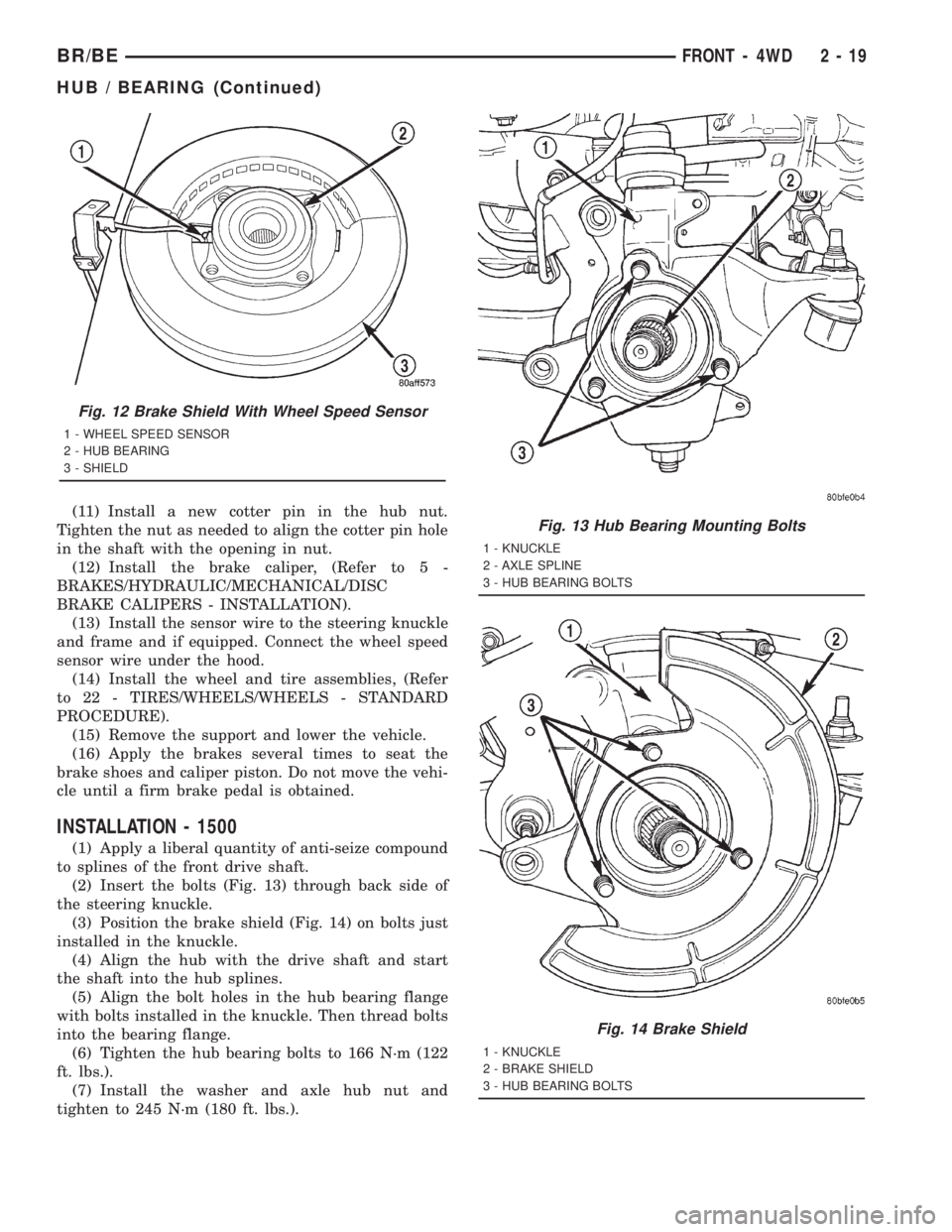
(2) Insert the bolts (Fig. 13) through back side of
the steering knuckle.
(3) Position the brake shield (Fig. 14) on bolts just
installed in the knuckle.
(4) Align the hub with the drive shaft and start
the shaft into the hub splines.
(5) Align the bolt holes in the hub bearing flange
with bolts installed in the knuckle. Then thread bolts
into the bearing flange.
(6) Tighten the hub bearing bolts to 166 N´m (122
ft. lbs.).
(7) Install the washer and axle hub nut and
tighten to 245 N´m (180 ft. lbs.).
Fig. 12 Brake Shield With Wheel Speed Sensor
1 - WHEEL SPEED SENSOR
2 - HUB BEARING
3 - SHIELD
Fig. 13 Hub Bearing Mounting Bolts
1 - KNUCKLE
2 - AXLE SPLINE
3 - HUB BEARING BOLTS
Fig. 14 Brake Shield
1 - KNUCKLE
2 - BRAKE SHIELD
3 - HUB BEARING BOLTS
BR/BEFRONT - 4WD 2 - 19
HUB / BEARING (Continued)