ECO mode DODGE RAM 2001 Service Repair Manual
[x] Cancel search | Manufacturer: DODGE, Model Year: 2001, Model line: RAM, Model: DODGE RAM 2001Pages: 2889, PDF Size: 68.07 MB
Page 2 of 2889
INTRODUCTION
TABLE OF CONTENTS
page page
BODY CODE PLATE
DESCRIPTION............................1
FASTENER IDENTIFICATION
DESCRIPTION............................3
FASTENER USAGE
DESCRIPTION............................6
INTERNATIONAL VEHICLE CONTROL &
DISPLAY SYMBOLS
DESCRIPTION............................6
METRIC SYSTEM
DESCRIPTION............................6TORQUE REFERENCES
DESCRIPTION............................9
VECI LABEL
DESCRIPTION...........................10
OPERATION.............................10
VEHICLE IDENTIFICATION NUMBER
DESCRIPTION...........................10
VEHICLE SAFETY CERTIFICATION LABEL
DESCRIPTION...........................12
EQUIPMENT IDENTIFICATION PLATE
DESCRIPTION...........................12
BODY CODE PLATE
DESCRIPTION
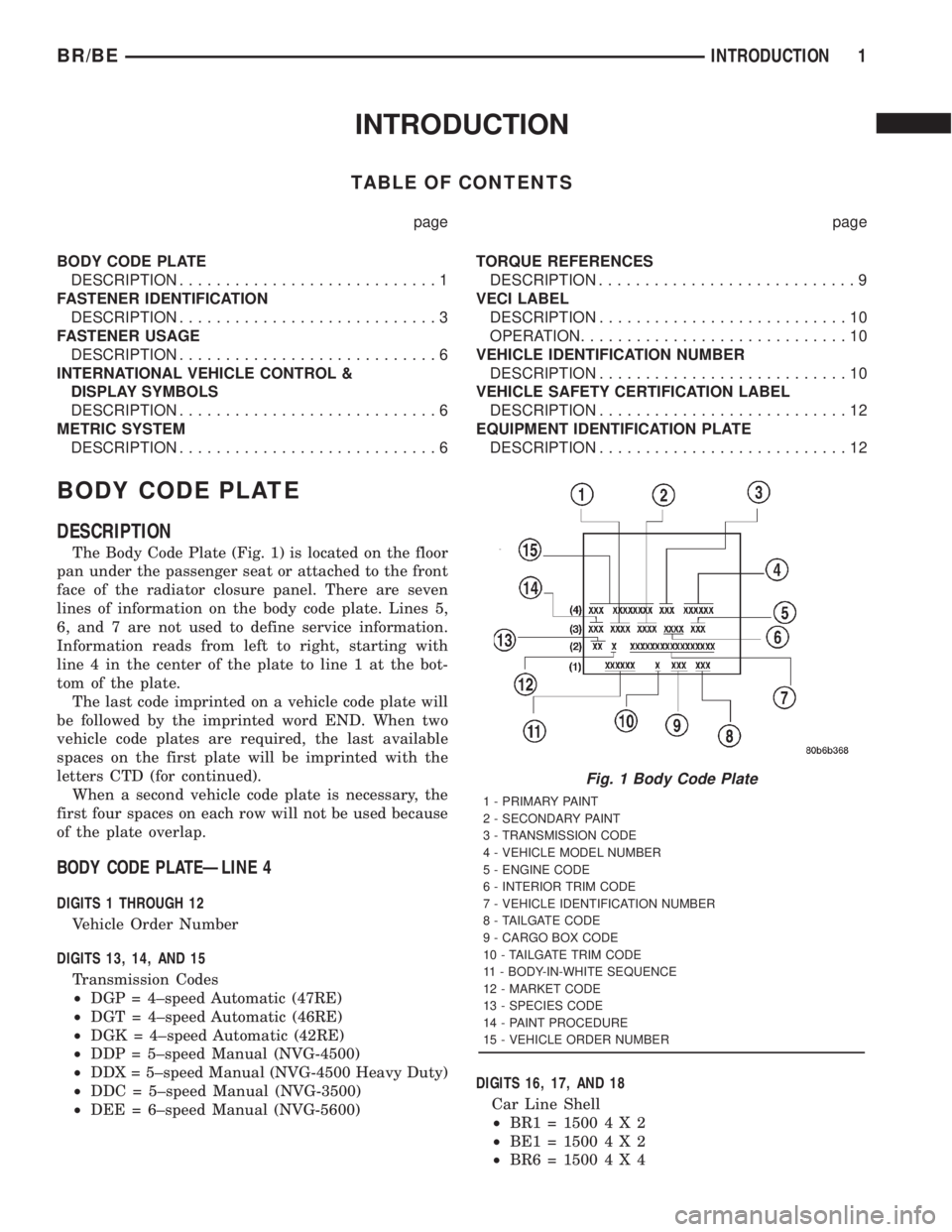
The Body Code Plate (Fig. 1) is located on the floor
pan under the passenger seat or attached to the front
face of the radiator closure panel. There are seven
lines of information on the body code plate. Lines 5,
6, and 7 are not used to define service information.
Information reads from left to right, starting with
line 4 in the center of the plate to line 1 at the bot-
tom of the plate.
The last code imprinted on a vehicle code plate will
be followed by the imprinted word END. When two
vehicle code plates are required, the last available
spaces on the first plate will be imprinted with the
letters CTD (for continued).
When a second vehicle code plate is necessary, the
first four spaces on each row will not be used because
of the plate overlap.
BODY CODE PLATEÐLINE 4
DIGITS 1 THROUGH 12
Vehicle Order Number
DIGITS 13, 14, AND 15
Transmission Codes
²DGP = 4±speed Automatic (47RE)
²DGT = 4±speed Automatic (46RE)
²DGK = 4±speed Automatic (42RE)
²DDP = 5±speed Manual (NVG-4500)
²DDX = 5±speed Manual (NVG-4500 Heavy Duty)
²DDC = 5±speed Manual (NVG-3500)
²DEE = 6±speed Manual (NVG-5600)DIGITS 16, 17, AND 18
Car Line Shell
²BR1=15004X2
²BE1=15004X2
²BR6=15004X4
Fig. 1 Body Code Plate
1 - PRIMARY PAINT
2 - SECONDARY PAINT
3 - TRANSMISSION CODE
4 - VEHICLE MODEL NUMBER
5 - ENGINE CODE
6 - INTERIOR TRIM CODE
7 - VEHICLE IDENTIFICATION NUMBER
8 - TAILGATE CODE
9 - CARGO BOX CODE
10 - TAILGATE TRIM CODE
11 - BODY-IN-WHITE SEQUENCE
12 - MARKET CODE
13 - SPECIES CODE
14 - PAINT PROCEDURE
15 - VEHICLE ORDER NUMBER
BR/BEINTRODUCTION 1
Page 20 of 2889
MAINTENANCE SCHEDULES
LIGHT DUTY ENGINE (1500 AND 2500
MODELS EXCEPT 8.0L) MAINTENANCE
SCHEDULES
There are two maintenance schedules that show
proper service for the vehicle.
First is ScheduleªAº. It lists all the scheduled
maintenance to be performed under ªnormalº operat-
ing conditions.
Second is ScheduleªBºIt is a schedule for vehicles
that are operated under the conditions listed at the
beginning of that schedule.
Use the schedule that best describes the driving
conditions.
Where time and mileage are listed, follow the
interval that occurs first.
At Each Stop For Fuel
²Check engine oil level and add as required.
²Check windshield washer solvent and add as
required.
²Clean windshield and wiper blades as required.
Once A Month
²Check tire pressure and look for unusual wear
or damage.
²Inspect battery and clean and tighten terminals
as required.
²Check fluid levels of coolant reservoir, brake
master cylinder, power steering, and transmission
and add as needed.
²Check all lights and all other electrical items for
correct operation.
²Inspect and clean wiper blades. Replace if
required.
At Each Oil Change
²Inspect exhaust system.
²Inspect brake hoses.
²Adjust rear brake shoe to drum clearance.
²Rotate the tires at each oil change interval
shown on schedule ªAº (7,500 Miles) or every other
interval shown on schedule ªBº (6,000 Miles).
²Check engine coolant level, hoses, and clamps.
²Lubricate steering linkage.
EMISSION CONTROL SYSTEM MAINTENANCE
The scheduled emission maintenance listed inbold
typeon the Maintenance Schedules, must be done at
the mileage specified to assure the continued proper
functioning of the emission control system. These,
and all other maintenance services included in this
manual, should be done to provide the best vehicle
performance and reliability. More frequent mainte-
nance may be needed for vehicles in severe operatingconditions such as dusty areas and very short trip
driving.
FLUID FILL LOCATIONS AND LUBRICATION
POINTS
The fluid check/fill locations and lubrication points
are located in each applicable group.
LIGHT DUTY SCHEDULE ªAº
7,500 Miles (12 000 km) or at 6 months
²Change engine oil.
²Replace engine oil filter.
²Inspect engine coolant level, hoses, and clamps.
²Inspect brake hoses.
²Lubricate the steering linkages.
²Check manual transmission fluid level.
²Inspect exhaust system.
15,000 Miles (24 000 km) or at 12 months
²Change engine oil.
²Replace engine oil filter.
²Inspect engine coolant level, hoses, and clamps.
²Inspect brake hoses.
²Lubricate the steering linkages.
²Check manual transmission fluid level.
²Inspect exhaust system.
22,500 Miles (36 000 km) or at 18 months
²Change engine oil.
²Replace engine oil filter.
²Inspect engine coolant level, hoses, and clamps.
²Inspect brake hoses.
²Inspect brake linings.
²Inspect front wheel bearings. Clean and repack,
if required (4x2).
²Lubricate the steering linkages.
²Lubricate non permanently sealed ball joints.
²Check manual transmission fluid level.
²Inspect exhaust system.
30,000 Miles (48 000 km) or at 24 months
²Replace engine air cleaner element.
²Replace spark plugs.
²Change engine oil.
²Replace engine oil filter.
²Inspect engine coolant level, hoses, and clamps.
²Inspect brake hoses.
²Lubricate the steering linkages.
²Inspect manual transmission fluid level.
²Inspect exhaust system.
37,500 Miles (60 000 km) or at 30 months
²Change engine oil.
²Replace engine oil filter.
²Inspect engine coolant level, hoses, and clamps.
BR/BELUBRICATION & MAINTENANCE 0 - 7
Page 26 of 2889
²Change front axle fluid (4x4).
²Inspect exhaust system.
111,000 Miles (178 000 km)
²Change engine oil.
²Replace engine oil filter.
²Inspect engine coolant level, hoses, and clamps.
²Flush and replace engine coolant.
²Inspect brake hoses.
²Lubricate the steering linkages.
²Check manual transmission fluid level.
²Inspect exhaust system.
114,000 Miles (182 000 km)
²Change engine oil.
²Replace engine oil filter.
²Inspect engine coolant level, hoses, and clamps.
²Inspect brake hoses.
²Lubricate the steering linkages.
²Check manual transmission fluid level.
²Inspect exhaust system.
117,000 Miles (187 000 km)
²Change engine oil.
²Replace engine oil filter.
²Inspect engine coolant level, hoses, and clamps.
²Inspect brake hoses.
²Lubricate the steering linkages.
²Check manual transmission fluid level.
²Inspect exhaust system.
120,000 Miles (192 000 km)
²Replace engine air cleaner element.
²Replace ignition cables.
²
Inspect PCV valve and replace as necessary.*
²Replace spark plugs.
²Inspect auto tension drive belt and replace if
required.**
²Change engine oil.
²Replace engine oil filter.
²Inspect engine coolant level, hoses, and clamps.
²Inspect brake hoses.
²Inspect brake linings.
²Lubricate the steering linkages.
²Change automatic transmission fluid, filter and
adjust the bands.
²Check manual transmission fluid level.
²Change rear axle fluid.
²Change front axle fluid (4x4).
²Inspect exhaust system.
*This maintenance is recommended by Daimler-
Chrysler to the customer but it is not required to
maintain warranty on the PCV valve.
**This maintenance is not required if the belt was
previously replaced.
Inspection and service should also be performed
anytime a malfunction is observed or suspected.
DESCRIPTION - MEDIUM DUTY TRUCK
MAINTENANCE SCHEDULE (8.0L 2500 & 3500
MODELS Ð CALIFORNIA ONLY)
There are two maintenance schedules that show
proper service based on the conditions that the vehi-
cle is subjected to. Use the schedule that best
describes these conditions.
ScheduleªAº, lists all the scheduled maintenance
to be performed under normal operating conditions
for Medium Duty vehicles.
ScheduleªBº, lists maintenance recommended for
Medium Duty vehicles operated under the conditions
listed at the beginning of that schedule.
²Where the time and mileage are listed, follow
the interval that occurs first.
At Each Stop For Fuel
²Check engine oil level and add as required.
²Check windshield washer solvent and add as
required.
²Clean windshield and wiper blades as required.
Once A Month
²Check tire pressure and look for unusual wear
or damage.
²Inspect battery and clean and tighten terminals
as required.
²Check fluid levels of coolant reservoir, brake
master cylinder, power steering, and transmission
and add as needed.
²Check all lights and all other electrical items for
correct operation.
²
Inspect and clean wiper blades. Replace if required.
At Each Oil Change
²Inspect exhaust system.
²Inspect brake hoses.
²Adjust rear brakes.
²Rotate the tires at each oil change interval
shown on schedule ªAº (6,000 Miles) or every other
interval shown on schedule ªBº (6,000 Miles)
²Check engine coolant level, hoses and clamps.
²Lubricate steering linkage.
EMISSION CONTROL SYSTEM MAINTENANCE
The scheduled emission maintenance listed inbold
typeon the Maintenance Schedules, must be done at
the mileage specified to assure the continued proper
functioning of the emission control system. These,
and all other maintenance services included in this
manual, should be done to provide the best vehicle
performance and reliability. More frequent mainte-
nance may be needed for vehicles in severe operating
conditions such as dusty areas and very short trip
driving.
BR/BELUBRICATION & MAINTENANCE 0 - 13
MAINTENANCE SCHEDULES (Continued)
Page 30 of 2889
²Inspect brake linings.
³Off-the-highway operation, trailer towing snow
plowing, prolonged operation with heavy loading,
especially in hot weather require the more frequent
transmission service indicated with an ³ in Schedule
ªBº. Perform these services if the vehicle is usually
operated under these conditions.
Inspection and service should also be performed
anytime a malfunction is observed or suspected.
DESCRIPTION - HEAVY DUTY ENGINE
(FEDERAL ONLY ± 2500 8.0L HD AND 3500
5.9L& 8.0L MODELS) MAINTENANCE
SCHEDULES
There are two maintenance schedules that show
proper service based on the conditions that the vehi-
cle is subjected to. Use the schedule that best
describes these conditions.
ScheduleªAº, lists all the scheduled maintenance
to be performed under normal operating conditions
for Heavy Duty vehicles.
ScheduleªBº, lists maintenance recommended for
Heavy Duty vehicles operated under the conditions
listed at the beginning of that schedule.
²Where time and mileage are listed, follow the
interval that occurs first.
At Each Stop For Fuel
²Check engine oil level, add as required.
²Check windshield washer solvent and add if
required.
²Clean windshield and wiper blades as required.
Once A Month
²Check tire pressure and look for unusual wear
or damage.
²Inspect battery and clean and tighten terminals
as required.
²Check fluid levels of coolant reservoir, power
steering and transmission and add as needed.
²Check all lights and all other electrical items for
correct operation.
²Inspect and clean wiper blades. Replace if
required.
At Each Oil Change
²Inspect exhaust system.
²Inspect brake hoses.
²Adjust rear brakes.
²Rotate the tires at each oil change interval
shown on schedule ªAº (6,000 Miles) or every other
interval shown on schedule ªBº (6,000 Miles).
²Check engine coolant level, hoses, and clamps.
²Lubricate steering linkage.
EMISSION CONTROL SYSTEM MAINTENANCE
The scheduled emission maintenance listed inbold
typeon the Maintenance Schedules, must be done at
the mileage specified to assure the continued proper
functioning of the emission control system. These,
and all other maintenance services included in this
manual, should be done to provide the best vehicle
performance and reliability. More frequent mainte-
nance may be needed for vehicles in severe operating
conditions such as dusty areas and very short trip
driving.
FLUID FILL LOCATIONS AND LUBRICATION
POINTS
The fluid fill/check locations and lubrication points
are located in each applicable group.
HEAVY DUTY SCHEDULE ªAº
6,000 miles (10 000 km) or at 6 months
²Change engine oil.
²Replace engine oil filter.
12,000 Miles (19 000 km) or at 12 months
²Change engine oil.
²Replace engine oil filter.
²Inspect engine air cleaner element, replace
as necessary (8.0L only).
18,000 Miles (29 000 km) or at 18 months
²Change engine oil.
²Replace engine oil filter.
²Inspect brake linings
²Inspect front wheel bearings. Clean and repack,
if required (4x4).
24,000 Miles (38 000 km) or at 24 months
²Change engine oil.
²Replace engine oil filter.
²Replace engine air cleaner element and air
pump filter.
²Clean and lubricate crankcase inlet air filter
(5.9L).
²Drain and refill automatic transmission fluid.
Replace filter and adjust bands.
²Inspect front wheel bearings. Clean and repack,
if required (4x2).
30,000 Miles (48 000 km) or at 30 months
²Change engine oil.
²Replace engine oil filter.
²Replace spark plugs.
36,000 Miles (58 000 km) or at 36 months
²Change engine oil.
²Replace engine oil filter.
BR/BELUBRICATION & MAINTENANCE 0 - 17
MAINTENANCE SCHEDULES (Continued)
Page 103 of 2889
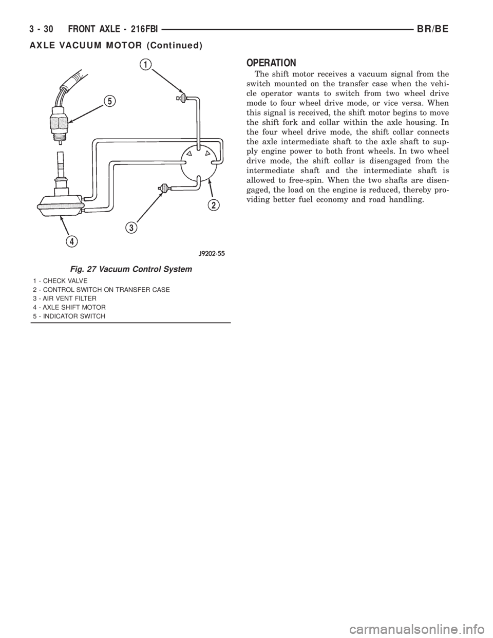
OPERATION
The shift motor receives a vacuum signal from the
switch mounted on the transfer case when the vehi-
cle operator wants to switch from two wheel drive
mode to four wheel drive mode, or vice versa. When
this signal is received, the shift motor begins to move
the shift fork and collar within the axle housing. In
the four wheel drive mode, the shift collar connects
the axle intermediate shaft to the axle shaft to sup-
ply engine power to both front wheels. In two wheel
drive mode, the shift collar is disengaged from the
intermediate shaft and the intermediate shaft is
allowed to free-spin. When the two shafts are disen-
gaged, the load on the engine is reduced, thereby pro-
viding better fuel economy and road handling.
Fig. 27 Vacuum Control System
1 - CHECK VALVE
2 - CONTROL SWITCH ON TRANSFER CASE
3 - AIR VENT FILTER
4 - AXLE SHIFT MOTOR
5 - INDICATOR SWITCH
3 - 30 FRONT AXLE - 216FBIBR/BE
AXLE VACUUM MOTOR (Continued)
Page 135 of 2889
AXLE VACUUM MOTOR
DESCRIPTION
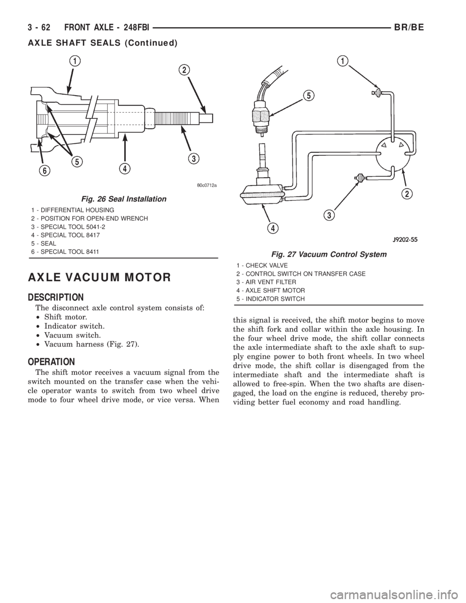
The disconnect axle control system consists of:
²Shift motor.
²Indicator switch.
²Vacuum switch.
²Vacuum harness (Fig. 27).
OPERATION
The shift motor receives a vacuum signal from the
switch mounted on the transfer case when the vehi-
cle operator wants to switch from two wheel drive
mode to four wheel drive mode, or vice versa. Whenthis signal is received, the shift motor begins to move
the shift fork and collar within the axle housing. In
the four wheel drive mode, the shift collar connects
the axle intermediate shaft to the axle shaft to sup-
ply engine power to both front wheels. In two wheel
drive mode, the shift collar is disengaged from the
intermediate shaft and the intermediate shaft is
allowed to free-spin. When the two shafts are disen-
gaged, the load on the engine is reduced, thereby pro-
viding better fuel economy and road handling.
Fig. 26 Seal Installation
1 - DIFFERENTIAL HOUSING
2 - POSITION FOR OPEN-END WRENCH
3 - SPECIAL TOOL 5041-2
4 - SPECIAL TOOL 8417
5 - SEAL
6 - SPECIAL TOOL 8411
Fig. 27 Vacuum Control System
1 - CHECK VALVE
2 - CONTROL SWITCH ON TRANSFER CASE
3 - AIR VENT FILTER
4 - AXLE SHIFT MOTOR
5 - INDICATOR SWITCH
3 - 62 FRONT AXLE - 248FBIBR/BE
AXLE SHAFT SEALS (Continued)
Page 300 of 2889
(6) Position adjuster lever return spring on pivot.
(7) Install adjuster lever.
(8) Attach adjuster cable to adjuster lever. Be sure
cable is properly routed.
(9) Adjust brake shoes to drum with brake gauge.
MASTER CYLINDER
DESCRIPTION
A two-piece master cylinder is used on all models.
The cylinder body containing the primary and sec-
ondary pistons is made of aluminum. The removable
fluid reservoir is made of nylon reinforced with glass
fiber. The reservoir stores reserve brake fluid for the
hydraulic brake circuits. The reservoir is the only
serviceable component.
The fluid compartments of the nylon reservoir are
interconnected to permit fluid level equalization.
However, the equalization feature does not affect cir-
cuit separation in the event of a front or rear brake
malfunction. The reservoir compartments will retain
enough fluid to operate the functioning hydraulic cir-
cuit.
Care must be exercised when removing/installing
the master cylinder connecting lines. The threads in
the cylinder fluid ports can be damaged if care is not
exercised. Start all brake line fittings by hand to
avoid cross threading.
The cylinder reservoir can be replaced when neces-
sary. However, the aluminum body section of the
master cylinder is not a repairable component.
NOTE: If diagnosis indicates that an internal mal-
function has occurred, the aluminum body section
must be replaced as an assembly.
OPERATION
The master cylinder bore contains a primary and
secondary piston. The primary piston supplies
hydraulic pressure to the front brakes. The secondary
piston supplies hydraulic pressure to the rear brakes.
DIAGNOSIS AND TESTING - MASTER
CYLINDER/POWER BOOSTER
(1) Start engine and check booster vacuum hose
connections. A hissing noise indicates vacuum leak.
Correct any vacuum leak before proceeding.
(2) Stop engine and shift transmission into Neu-
tral.
(3) Pump brake pedal until all vacuum reserve in
booster is depleted.
(4) Press and hold brake pedal under light foot
pressure. The pedal should hold firm, if the pedal
falls away master cylinder is faulty (internal leak-
age).
(5) Start engine and note pedal action. It should
fall away slightly under light foot pressure then hold
firm. If no pedal action is discernible, power booster,
vacuum supply, or vacuum check valve is faulty. Pro-
ceed to the POWER BOOSTER VACUUM TEST.
(6) If the POWER BOOSTER VACUUM TEST
passes, rebuild booster vacuum reserve as follows:
Release brake pedal. Increase engine speed to 1500
rpm, close the throttle and immediately turn off igni-
tion to stop engine.
(7) Wait a minimum of 90 seconds and try brake
action again. Booster should provide two or more vac-
uum assisted pedal applications. If vacuum assist is
not provided, booster is faulty.
POWER BOOSTER VACUUM TEST
(1) Connect vacuum gauge to booster check valve
with short length of hose and T-fitting (Fig. 54).
(2) Start and run engine at curb idle speed for one
minute.
(3) Observe the vacuum supply. If vacuum supply
is not adequate, repair vacuum supply.
(4) Clamp hose shut between vacuum source and
check valve.
(5) Stop engine and observe vacuum gauge.
(6) If vacuum drops more than one inch HG (33
millibars) within 15 seconds, booster diaphragm or
check valve is faulty.
POWER BOOSTER CHECK VALVE TEST
(1) Disconnect vacuum hose from check valve.
(2) Remove check valve and valve seal from
booster.
(3) Use a hand operated vacuum pump for test.
(4) Apply 15-20 inches vacuum at large end of
check valve (Fig. 55).
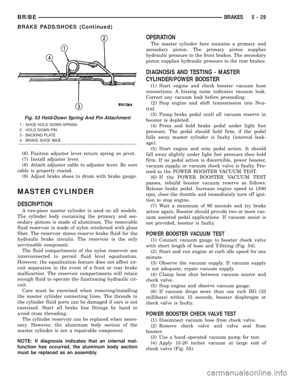
Fig. 53 Hold-Down Spring And Pin Attachment
1 - SHOE HOLD DOWN SPRING
2 - HOLD DOWN PIN
3 - BACKING PLATE
4 - BRAKE SHOE WEB
BR/BEBRAKES 5 - 29
BRAKE PADS/SHOES (Continued)
Page 303 of 2889
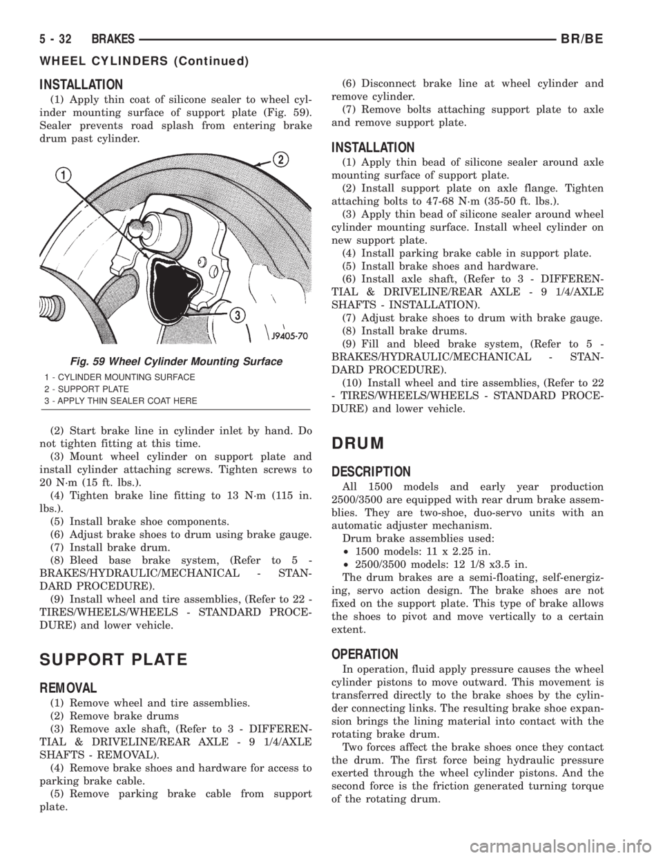
INSTALLATION
(1) Apply thin coat of silicone sealer to wheel cyl-
inder mounting surface of support plate (Fig. 59).
Sealer prevents road splash from entering brake
drum past cylinder.
(2) Start brake line in cylinder inlet by hand. Do
not tighten fitting at this time.
(3) Mount wheel cylinder on support plate and
install cylinder attaching screws. Tighten screws to
20 N´m (15 ft. lbs.).
(4) Tighten brake line fitting to 13 N´m (115 in.
lbs.).
(5) Install brake shoe components.
(6) Adjust brake shoes to drum using brake gauge.
(7) Install brake drum.
(8) Bleed base brake system, (Refer to 5 -
BRAKES/HYDRAULIC/MECHANICAL - STAN-
DARD PROCEDURE).
(9) Install wheel and tire assemblies, (Refer to 22 -
TIRES/WHEELS/WHEELS - STANDARD PROCE-
DURE) and lower vehicle.
SUPPORT PLATE
REMOVAL
(1) Remove wheel and tire assemblies.
(2) Remove brake drums
(3) Remove axle shaft, (Refer to 3 - DIFFEREN-
TIAL & DRIVELINE/REAR AXLE - 9 1/4/AXLE
SHAFTS - REMOVAL).
(4) Remove brake shoes and hardware for access to
parking brake cable.
(5) Remove parking brake cable from support
plate.(6) Disconnect brake line at wheel cylinder and
remove cylinder.
(7) Remove bolts attaching support plate to axle
and remove support plate.
INSTALLATION
(1) Apply thin bead of silicone sealer around axle
mounting surface of support plate.
(2) Install support plate on axle flange. Tighten
attaching bolts to 47-68 N´m (35-50 ft. lbs.).
(3) Apply thin bead of silicone sealer around wheel
cylinder mounting surface. Install wheel cylinder on
new support plate.
(4) Install parking brake cable in support plate.
(5) Install brake shoes and hardware.
(6) Install axle shaft, (Refer to 3 - DIFFEREN-
TIAL & DRIVELINE/REAR AXLE - 9 1/4/AXLE
SHAFTS - INSTALLATION).
(7) Adjust brake shoes to drum with brake gauge.
(8) Install brake drums.
(9) Fill and bleed brake system, (Refer to 5 -
BRAKES/HYDRAULIC/MECHANICAL - STAN-
DARD PROCEDURE).
(10) Install wheel and tire assemblies, (Refer to 22
- TIRES/WHEELS/WHEELS - STANDARD PROCE-
DURE) and lower vehicle.
DRUM
DESCRIPTION
All 1500 models and early year production
2500/3500 are equipped with rear drum brake assem-
blies. They are two-shoe, duo-servo units with an
automatic adjuster mechanism.
Drum brake assemblies used:
²1500 models: 11 x 2.25 in.
²2500/3500 models: 12 1/8 x3.5 in.
The drum brakes are a semi-floating, self-energiz-
ing, servo action design. The brake shoes are not
fixed on the support plate. This type of brake allows
the shoes to pivot and move vertically to a certain
extent.
OPERATION
In operation, fluid apply pressure causes the wheel
cylinder pistons to move outward. This movement is
transferred directly to the brake shoes by the cylin-
der connecting links. The resulting brake shoe expan-
sion brings the lining material into contact with the
rotating brake drum.
Two forces affect the brake shoes once they contact
the drum. The first force being hydraulic pressure
exerted through the wheel cylinder pistons. And the
second force is the friction generated turning torque
of the rotating drum.
Fig. 59 Wheel Cylinder Mounting Surface
1 - CYLINDER MOUNTING SURFACE
2 - SUPPORT PLATE
3 - APPLY THIN SEALER COAT HERE
5 - 32 BRAKESBR/BE
WHEEL CYLINDERS (Continued)
Page 306 of 2889
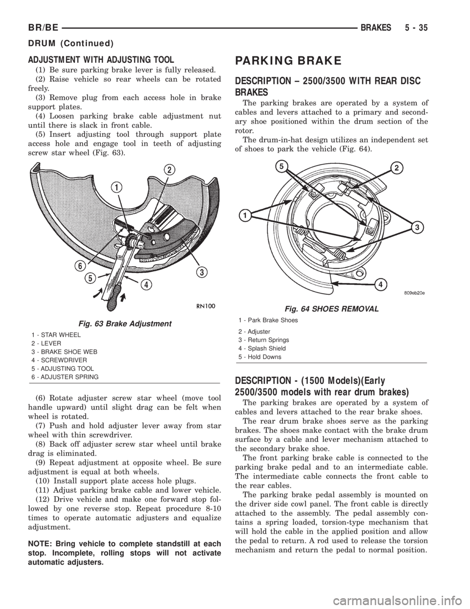
ADJUSTMENT WITH ADJUSTING TOOL
(1) Be sure parking brake lever is fully released.
(2) Raise vehicle so rear wheels can be rotated
freely.
(3) Remove plug from each access hole in brake
support plates.
(4) Loosen parking brake cable adjustment nut
until there is slack in front cable.
(5) Insert adjusting tool through support plate
access hole and engage tool in teeth of adjusting
screw star wheel (Fig. 63).
(6) Rotate adjuster screw star wheel (move tool
handle upward) until slight drag can be felt when
wheel is rotated.
(7) Push and hold adjuster lever away from star
wheel with thin screwdriver.
(8) Back off adjuster screw star wheel until brake
drag is eliminated.
(9) Repeat adjustment at opposite wheel. Be sure
adjustment is equal at both wheels.
(10) Install support plate access hole plugs.
(11) Adjust parking brake cable and lower vehicle.
(12) Drive vehicle and make one forward stop fol-
lowed by one reverse stop. Repeat procedure 8-10
times to operate automatic adjusters and equalize
adjustment.
NOTE: Bring vehicle to complete standstill at each
stop. Incomplete, rolling stops will not activate
automatic adjusters.
PARKING BRAKE
DESCRIPTION ± 2500/3500 WITH REAR DISC
BRAKES
The parking brakes are operated by a system of
cables and levers attached to a primary and second-
ary shoe positioned within the drum section of the
rotor.
The drum-in-hat design utilizes an independent set
of shoes to park the vehicle (Fig. 64).
DESCRIPTION - (1500 Models)(Early
2500/3500 models with rear drum brakes)
The parking brakes are operated by a system of
cables and levers attached to the rear brake shoes.
The rear drum brake shoes serve as the parking
brakes. The shoes make contact with the brake drum
surface by a cable and lever mechanism attached to
the secondary brake shoe.
The front parking brake cable is connected to the
parking brake pedal and to an intermediate cable.
The intermediate cable connects the front cable to
the rear cables.
The parking brake pedal assembly is mounted on
the driver side cowl panel. The front cable is directly
attached to the assembly. The pedal assembly con-
tains a spring loaded, torsion-type mechanism that
will hold the cable in the applied position and allow
the pedal to return. A rod used to release the torsion
mechanism and return the pedal to normal position.
Fig. 63 Brake Adjustment
1 - STAR WHEEL
2 - LEVER
3 - BRAKE SHOE WEB
4 - SCREWDRIVER
5 - ADJUSTING TOOL
6 - ADJUSTER SPRING
Fig. 64 SHOES REMOVAL
1 - Park Brake Shoes
2 - Adjuster
3 - Return Springs
4 - Splash Shield
5 - Hold Downs
BR/BEBRAKES 5 - 35
DRUM (Continued)
Page 307 of 2889
OPERATION - 2500/3500 WITH REAR DISC
BRAKES
To apply the parking brake the pedal is depressed.
This creates tension in the cable which pulls forward
on the park brake lever. The lever pushes the park
brake shoes outward and into contact with the drum
section of the rotor. The contact of shoe to rotor parks
the vehicle.
A torsion locking mechanism is used to hold the
pedal in an applied position. Parking brake release is
accomplished by the hand release.
A parking brake switch is mounted on the parking
brake lever and is actuated by movement of the
lever. The switch, which is in circuit with the red
warning light in the dash, will illuminate the warn-
ing light whenever the parking brake is applied.
Parking brake adjustment is controlled by a cable
tensioner mechanism. The cable tensioner, once
adjusted at the factory, should not need further
adjustment under normal circumstances. Adjustment
may be required if a new tensioner, or cables are
installed, or disconnected.
OPERATION - (1500 models) (Early 2500/3500
models with rear drum brakes)
To apply the parking brakes, the pedal is
depressed. This pulls the rear brake shoe actuating
levers forward. As the actuating lever is pulled for-
ward, the parking brake strut or cam, exerts a linear
force against the primary brake shoe. This action
presses the primary shoe into contact with the drum.
Once the primary shoe contacts the drum, force is
exerted through the strut/cam. This force is trans-
ferred through the strut/cam to the secondary brake
shoe causing it to pivot into the drum as well.
A torsion locking mechanism is used to hold the
pedal in an applied position. Parking brake release is
accomplished by the hand release.
A parking brake switch is mounted on the parking
brake lever and is actuated by movement of the
lever. The switch, which is in circuit with the red
warning light in the dash, will illuminate the warn-
ing light whenever the parking brake is applied.
Parking brake adjustment is controlled by a cable
tensioner mechanism. The cable tensioner, once
adjusted at the factory, should not need further
adjustment under normal circumstances. Adjustment
may be required if a new tensioner, or cables are
installed, or disconnected.
PEDAL
REMOVAL
(1) Release the parking brake.
(2) Raise the vehicle.(3) Loosen the cable tensioner nut at the equalizer
to create slack in the front cable.
(4) Lower the vehicle.
(5) Remove the knee bolster, (Refer to 23 - BODY/
INSTRUMENT PANEL/STEERING COLUMN
OPENING COVER - REMOVAL).
(6) Disconnect the brake lamp wire from the
switch on the pedal assembly.
(7) Roll the carpet back, loosen the front cable
grommet from the floorpan and the cable retainer.
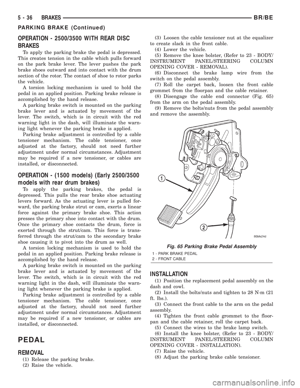
(8) Disengage the cable end connector (Fig. 65)
from the arm on the pedal assembly.
(9) Remove the bolts/nuts from the pedal assembly
and remove the assembly.
INSTALLATION
(1) Position the replacement pedal assembly on the
dash and cowl.
(2) Install the bolts/nuts and tighten to 28 N´m (21
ft. lbs.).
(3) Connect the front cable to the arm on the pedal
assembly.
(4) Tighten the front cable grommet to the floor-
pan and the cable retainer, roll the carpet back.
(5) Connect the wires to the brake lamp switch.
(6) Install the knee bolster, (Refer to 23 - BODY/
INSTRUMENT PANEL/STEERING COLUMN
OPENING COVER - INSTALLATION).
(7) Raise the vehicle.
(8) Adjust the parking brake cable tensioner.
Fig. 65 Parking Brake Pedal Assembly
1 - PARK BRAKE PEDAL
2 - FRONT CABLE
5 - 36 BRAKESBR/BE
PARKING BRAKE (Continued)