G113 DODGE RAM 2001 Service Repair Manual
[x] Cancel search | Manufacturer: DODGE, Model Year: 2001, Model line: RAM, Model: DODGE RAM 2001Pages: 2889, PDF Size: 68.07 MB
Page 808 of 2889
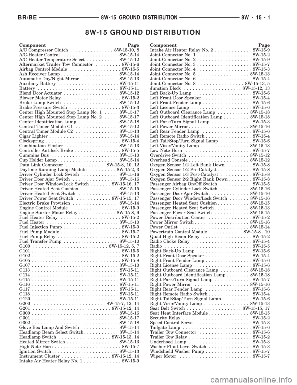
8W-15 GROUND DISTRIBUTION
Component Page
A/C Compressor Clutch............... 8W-15-10, 8
A/C-Heater Control.................... 8W-15-14
A/C Heater Temperature Select........... 8W-15-12
Aftermarket Trailer Tow Connector......... 8W-15-6
Airbag Control Module.................. 8W-15-5
Ash Receiver Lamp.................... 8W-15-14
Automatic Day/Night Mirror............. 8W-15-13
Auxiliary Battery..................... 8W-15-11
Battery............................ 8W-15-11
Blend Door Actuator................... 8W-15-12
Blower Motor Relay.................... 8W-15-2
Brake Lamp Switch................... 8W-15-12
Brake Pressure Switch.................. 8W-15-3
Center High Mounted Stop Lamp No. 1..... 8W-15-17
Center High Mounted Stop Lamp No. 2..... 8W-15-17
Center Identification Lamp.............. 8W-15-18
Central Timer Module C1............... 8W-15-12
Central Timer Module C2............... 8W-15-13
Cigar Lighter........................ 8W-15-14
Clockspring.......................... 8W-15-4
Combination Flasher.................. 8W-15-13
Controller Antilock Brake................ 8W-15-5
Cummins Bus....................... 8W-15-10
Cup Holder Lamp..................... 8W-15-14
Data Link Connector.............. 8W-15-8, 10, 12
Daytime Running Lamp Module......... 8W-15-2, 3
Driver Cylinder Lock Switch............. 8W-15-16
Driver Door Ajar Switch................ 8W-15-16
Driver Door Window/Lock Switch....... 8W-15-16, 17
Driver Heated Seat Cushion............. 8W-15-15
Driver Heated Seat Switch.............. 8W-15-13
Driver Power Seat Switch............ 8W-15-15, 17
Electric Brake Provision................ 8W-15-14
Engine Control Module.................. 8W-15-9
Engine Starter Motor Relay............. 8W-15-8, 9
Fuel Heater Relay..................... 8W-15-2
Fuel Heater......................... 8W-15-10
Fuel Injection Pump.................... 8W-15-9
Fuel Pump Module..................... 8W-15-7
Fuel Pump Relay...................... 8W-15-2
Fuel Transfer Pump................... 8W-15-10
G100.......................... 8W-15-12, 5, 7
G101............................... 8W-15-5
G102............................... 8W-15-2
G105............................... 8W-15-8
G107.............................. 8W-15-10
G113 .............................. 8W-15-11
G114 .............................. 8W-15-11
G115 .............................. 8W-15-11
G116 .............................. 8W-15-11
G117 .............................. 8W-15-11
G118 .............................. 8W-15-11
G120.............................. 8W-15-11
G200......................... 8W-15-7, 12, 14
G201........................... 8W-15-12, 14
G300.............................. 8W-15-16
G301.............................. 8W-15-17
G302.............................. 8W-15-18
Glove Box Lamp And Switch............. 8W-15-14
Headlamp Beam Select Switch............ 8W-15-14
Headlamp Switch.................. 8W-15-13, 14
Heated Mirror Switch.................. 8W-15-13
High Note Horn....................... 8W-15-7
Ignition Switch....................... 8W-15-13
Instrument Cluster................. 8W-15-12, 14
Intake Air Heater Relay No. 1............. 8W-15-9Component Page
Intake Air Heater Relay No. 2............. 8W-15-9
Joint Connector No. 1................... 8W-15-2
Joint Connector No. 2................... 8W-15-9
Joint Connector No. 3................... 8W-15-7
Joint Connector No. 4................... 8W-15-3
Joint Connector No. 5.................. 8W-15-13
Joint Connector No. 6................... 8W-15-4
Joint Connector No. 8................ 8W-15-13, 5
Junction Block.................... 8W-15-12, 13
Left Back-Up Lamp.................... 8W-15-6
Left Front Door Speaker................. 8W-15-4
Left Front Fender Lamp................. 8W-15-6
Left License Lamp..................... 8W-15-6
Left Outboard Clearance Lamp........... 8W-15-18
Left Outboard Identification Lamp......... 8W-15-18
Left Park/Turn Signal Lamp.............. 8W-15-3
Left Power Mirror..................... 8W-15-16
Left Rear Fender Lamp................. 8W-15-6
Left Remote Radio Switch................ 8W-15-4
Left Tail/Stop/Turn Signal Lamp........... 8W-15-6
Left Visor/Vanity Lamp................. 8W-15-13
Low Note Horn....................... 8W-15-7
Overdrive Switch..................... 8W-15-12
Overhead Console..................... 8W-15-12
Oxygen Sensor 1/2 Left Bank Down......... 8W-15-8
Oxygen Sensor 1/2 Pre-Catalyst............ 8W-15-8
Oxygen Sensor 1/3 Post-Catalyst........... 8W-15-8
Oxygen Sensor 2/2 Right Bank Down........ 8W-15-8
Passenger Airbag On/Off Switch........... 8W-15-5
Passenger Cylinder Lock Switch.......... 8W-15-16
Passenger Door Ajar Switch.............. 8W-15-16
Passenger Door Window/Lock Switch....... 8W-15-16
Passenger Heated Seat Cushion........... 8W-15-15
Passenger Heated Seat Switch............ 8W-15-13
Passenger Power Seat Switch............ 8W-15-15
Power Distribution Center............... 8W-15-2
Power Mirror Switch................... 8W-15-16
Power Outlet........................ 8W-15-14
Powertrain Control Module............ 8W-15-8 , 10
Quad High Beam Relay................. 8W-15-2
Radio Choke Relay..................... 8W-15-4
Radio.............................. 8W-15-5
Right Back-Up Lamp................... 8W-15-6
Right Front Door Speaker................ 8W-15-4
Right Front Fender Lamp................ 8W-15-6
Right License Lamp.................... 8W-15-6
Right Outboard Clearance Lamp.......... 8W-15-18
Right Outboard Identification Lamp........ 8W-15-18
Right Park/Turn Signal Lamp............. 8W-15-7
Right Power Mirror................... 8W-15-16
Right Rear Fender Lamp................ 8W-15-6
Right Remote Radio Switch............... 8W-15-4
Right Tail/Stop/Turn Signal Lamp.......... 8W-15-6
Right Visor/Vanity Lamp................ 8W-15-13
Seat Belt Switch................... 8W-15-15, 17
Seat Heat Interface Module.............. 8W-15-15
Security Relay........................ 8W-15-2
Speed Control Servo.................... 8W-15-3
Tailgate Lamp........................ 8W-15-6
Trailer Tow Connector.................. 8W-15-6
Trailer Tow Relay...................... 8W-15-2
Underhood Lamp...................... 8W-15-3
Washer Fluid Level Switch............... 8W-15-3
Windshield Washer Pump................ 8W-15-7
Wiper Motor......................... 8W-15-7
BR/BE8W-15 GROUND DISTRIBUTION 8W - 15 - 1
Page 830 of 2889
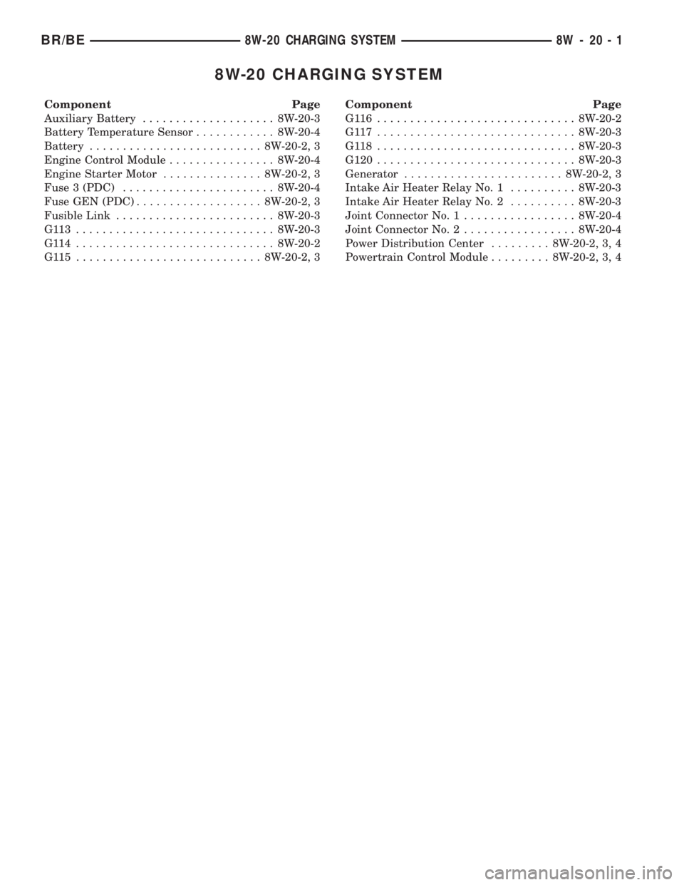
8W-20 CHARGING SYSTEM
Component Page
Auxiliary Battery.................... 8W-20-3
Battery Temperature Sensor............ 8W-20-4
Battery.......................... 8W-20-2, 3
Engine Control Module................ 8W-20-4
Engine Starter Motor............... 8W-20-2, 3
Fuse 3 (PDC)....................... 8W-20-4
Fuse GEN (PDC)................... 8W-20-2, 3
Fusible Link........................ 8W-20-3
G113 .............................. 8W-20-3
G114 .............................. 8W-20-2
G115 ............................ 8W-20-2, 3Component Page
G116 .............................. 8W-20-2
G117 .............................. 8W-20-3
G118 .............................. 8W-20-3
G120.............................. 8W-20-3
Generator........................ 8W-20-2, 3
Intake Air Heater Relay No. 1.......... 8W-20-3
Intake Air Heater Relay No. 2.......... 8W-20-3
Joint Connector No. 1................. 8W-20-4
Joint Connector No. 2................. 8W-20-4
Power Distribution Center......... 8W-20-2, 3, 4
Powertrain Control Module......... 8W-20-2, 3, 4
BR/BE8W-20 CHARGING SYSTEM 8W - 20 - 1
Page 838 of 2889
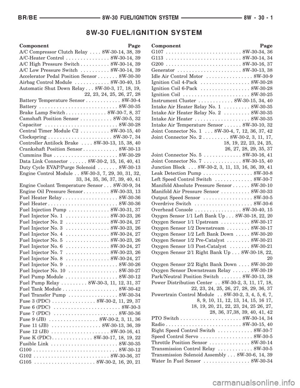
8W-30 FUEL/IGNITION SYSTEM
Component Page
A/C Compressor Clutch Relay.... 8W-30-14, 38, 39
A/C-Heater Control............... 8W-30-14, 39
A/C High Pressure Switch.......... 8W-30-14, 39
A/C Low Pressure Switch.......... 8W-30-14, 39
Accelerator Pedal Position Sensor....... 8W-30-30
Airbag Control Module............ 8W-30-40, 15
Automatic Shut Down Relay . . . 8W-30-3, 17, 18, 19,
22, 23, 24, 25, 26, 27, 28
Battery Temperature Sensor............ 8W-30-4
Battery........................... 8W-30-35
Brake Lamp Switch.............. 8W-30-7, 8, 37
Camshaft Position Sensor........... 8W-30-5, 32
Capacitor......................... 8W-30-28
Central Timer Module C2.......... 8W-30-15, 40
Clockspring...................... 8W-30-7, 34
Controller Antilock Brake.... 8W-30-13, 15, 38, 40
Crankshaft Position Sensor............ 8W-30-13
Cummins Bus...................... 8W-30-29
Data Link Connector...... 8W-30-2, 15, 16, 40, 41
Duty Cycle EVAP/Purge Solenoid....... 8W-30-13
Engine Control Module . . 8W-30-3, 7, 29, 30, 31, 32,
33, 34, 35, 36, 37, 39, 40, 41
Engine Coolant Temperature Sensor . . . 8W-30-9, 34
Engine Oil Pressure Sensor......... 8W-30-33, 13
Fuel Heater Relay................... 8W-30-36
Fuel Heater........................ 8W-30-36
Fuel Injection Pump.............. 8W-30-31, 37
Fuel Injector No. 1............... 8W-30-23, 26
Fuel Injector No. 2............... 8W-30-24, 27
Fuel Injector No. 3............... 8W-30-23, 26
Fuel Injector No. 4............... 8W-30-24, 27
Fuel Injector No. 5............... 8W-30-23, 26
Fuel Injector No. 6............... 8W-30-24, 27
Fuel Injector No. 7............... 8W-30-23, 26
Fuel Injector No. 8............... 8W-30-24, 27
Fuel Injector No. 9.................. 8W-30-26
Fuel Injector No. 10................. 8W-30-27
Fuel Pump Module.................. 8W-30-12
Fuel Pump Relay......... 8W-30-3, 11, 12, 31, 37
Fuel Tank Module................... 8W-30-42
Fuel Transfer Pump................. 8W-30-34
Fuse 3 (PDC)............... 8W-30-2, 11, 29, 37
Fuse 6 (PDC)....................... 8W-30-3
Fuse 7 (PDC)...................... 8W-30-36
Fuse 9 (JB)................. 8W-30-2, 3, 11, 36
Fuse 11 (JB)................. 8W-30-13, 36, 39
Fuse 12 (JB).................... 8W-30-16, 41
Fuse K (PDC).............. 8W-30-17, 18, 19, 22
Fusible Link....................... 8W-30-35
G100............................. 8W-30-12
G102.......................... 8W-30-36, 37
G105..................... 8W-30-2, 16, 20, 21Component Page
G107.......................... 8W-30-34, 36
G113 .......................... 8W-30-14, 34
G200.......................... 8W-30-16, 37
Generator...................... 8W-30-13, 38
Idle Air Control Motor................ 8W-30-9
Ignition Coil 4-Pack................. 8W-30-28
Ignition Coil 6-Pack................. 8W-30-28
Ignition Coil....................... 8W-30-25
Instrument Cluster............ 8W-30-15, 34, 40
Intake Air Heater Relay No. 1......... 8W-30-35
Intake Air Heater Relay No. 2......... 8W-30-35
Intake Air Heater................... 8W-30-35
Intake Air Temperature Sensor...... 8W-30-10, 32
Joint Connector No. 1 . . . 8W-30-4, 7, 12, 36, 37, 42
Joint Connector No. 2......... 8W-30-2, 3, 11, 17,
18, 19, 22, 23, 24, 25,
26, 27, 28, 29, 35, 37
Joint Connector No. 5............. 8W-30-16, 41
Joint Connector No. 7............. 8W-30-15, 40
Junction Block . . . 8W-30-2, 3, 11, 13, 16, 36, 39, 41
Leak Detection Pump................. 8W-30-8
Left Speed Control Switch............. 8W-30-7
Manifold Absolute Pressure Sensor...... 8W-30-10
Manifold Air Pressure Sensor.......... 8W-30-33
Output Speed Sensor................. 8W-30-5
Overdrive Switch.................... 8W-30-6
Overhead Console................ 8W-30-40, 15
Oxygen Sensor 1/1 Left Bank Up . . . 8W-30-18, 22, 20
Oxygen Sensor 1/1 Upstream.......... 8W-30-17
Oxygen Sensor 1/2 Downstream........ 8W-30-17
Oxygen Sensor 1/2 Left Bank Down..... 8W-30-20
Oxygen Sensor 1/2 Pre-Catalyst........ 8W-30-21
Oxygen Sensor 1/3 Post-Catalyst....... 8W-30-21
Oxygen Sensor 2/1 Right Bank Up . . . 8W-30-18, 22,
20
Oxygen Sensor 2/2 Right Bank Down.... 8W-30-20
Oxygen Sensor Downstream Relay...... 8W-30-19
Park/Neutral Position Switch....... 8W-30-13, 38
Power Distribution Center . . 8W-30-2, 3, 11, 17, 18,
22, 23, 24, 25, 26, 27, 28, 29, 36, 37
Powertrain Control Module . . 8W-30-2, 3, 4, 5, 6, 7,
8, 9, 10, 11, 12, 13, 14, 15, 16 17,
18, 19, 20, 21, 22, 23, 24, 25 26, 27,
28, 36, 37,38, 39, 40, 41, 42
PTO Switch..................... 8W-30-14, 34
Radio.......................... 8W-30-15, 40
Right Speed Control Switch............ 8W-30-7
Speed Control Servo.................. 8W-30-5
Throttle Position Sensor.............. 8W-30-14
Transmission Control Relay............ 8W-30-5
Transmission Solenoid Assembly . . . 8W-30-6, 14, 39
Water In Fuel Sensor................ 8W-30-34
BR/BE8W-30 FUEL/IGNITION SYSTEM 8W - 30 - 1
Page 1021 of 2889

C105 - (HEADLAMP AND DASH SIDE)
CAV CIRCUIT
1 L34 20RD/OR
2 L39 20LB
C106 - BLACK (HEADLAMP AND DASH SIDE)
CAV CIRCUIT
1 G107 20GY
2 Z1 20BK
C106 - BLACK (4X4 INDICATOR SIDE)
CAV CIRCUIT
1 G107 18BK/GY
2 Z1 18BK
C114 - BLACK (AMBIENT TEMPERATURE SEN-
SOR SIDE)
CAV CIRCUIT
1 G31 20VT/LG
2 G32 20BK/VT
C114 - BLACK (HEADLAMP AND DASH SIDE)
CAV CIRCUIT
1 G31 20VT/LG
2 G32 20BK/VT
C125 (DIESEL) - (TRANSMISSION SIDE)
CAV CIRCUIT
1 F18 18LG/BK
2 G113 18OR
3 A14 14RD/WT
4 C3 18DB/BK
5 C90 18LG/WT
6 K22 18OR/DB
7 A40 14RD/LG
8 K131 18BR/WT
9 A93 12RD/BK
10 K104 18BK/LB
11 G7 18WT/OR
8W - 80 - 8 8W-80 CONNECTOR PIN-OUTSBR/BE
Page 1022 of 2889

C125 (DIESEL) - (ENGINE SIDE)
CAV CIRCUIT
1 F18 18LG/BK
2 G113 18OR
3 A14 12RD/WT
4 C3 18DB/BK
5 C90 18LG/WT
6 K22 18OR/DB
7 A40 14RD/LG
8 K131 18BR/WT
9 A93 12RD/BK
10 K104 18BK/LB
11 G7 18WT/OR
C126 (DIESEL) - GRAY (TRANSMISSION SIDE)
CAV CIRCUIT
1 K20 18DG
2 V37 18RD/LG (A/T)
2 Z12 18BK/TN (M/T)
3 T125 18DB
4 D20 18DG
5 D21 18PK/DB
6 D1 18VT/BR
7 D2 18WT/BK
8 G85 18OR/BK
9 C22 18DB
10 K24 18GY/BK
11 V40 18WT/PK
12 Z12 18BK/TN
13 S21 18YL/BK
14 S22 18OR/BK
C126 (DIESEL) - GRAY (ENGINE SIDE)
CAV CIRCUIT
1 K20 18DG
2 V37 18RD/LG (M/T)
3 T125 18DB
4 D20 18DG
5 D21 18PK/DB
6 D1 18VT/BR
7 D2 18WT/BK
8 G85 18OR/BK
9 C22 18DB
10 K24 18GY/BK
11 V32 18YL/BK
12 Z12 18BK/TN
13 S21 18YL/BK
14 S22 18OR/BK
BR/BE8W-80 CONNECTOR PIN-OUTS 8W - 80 - 9
Page 1053 of 2889
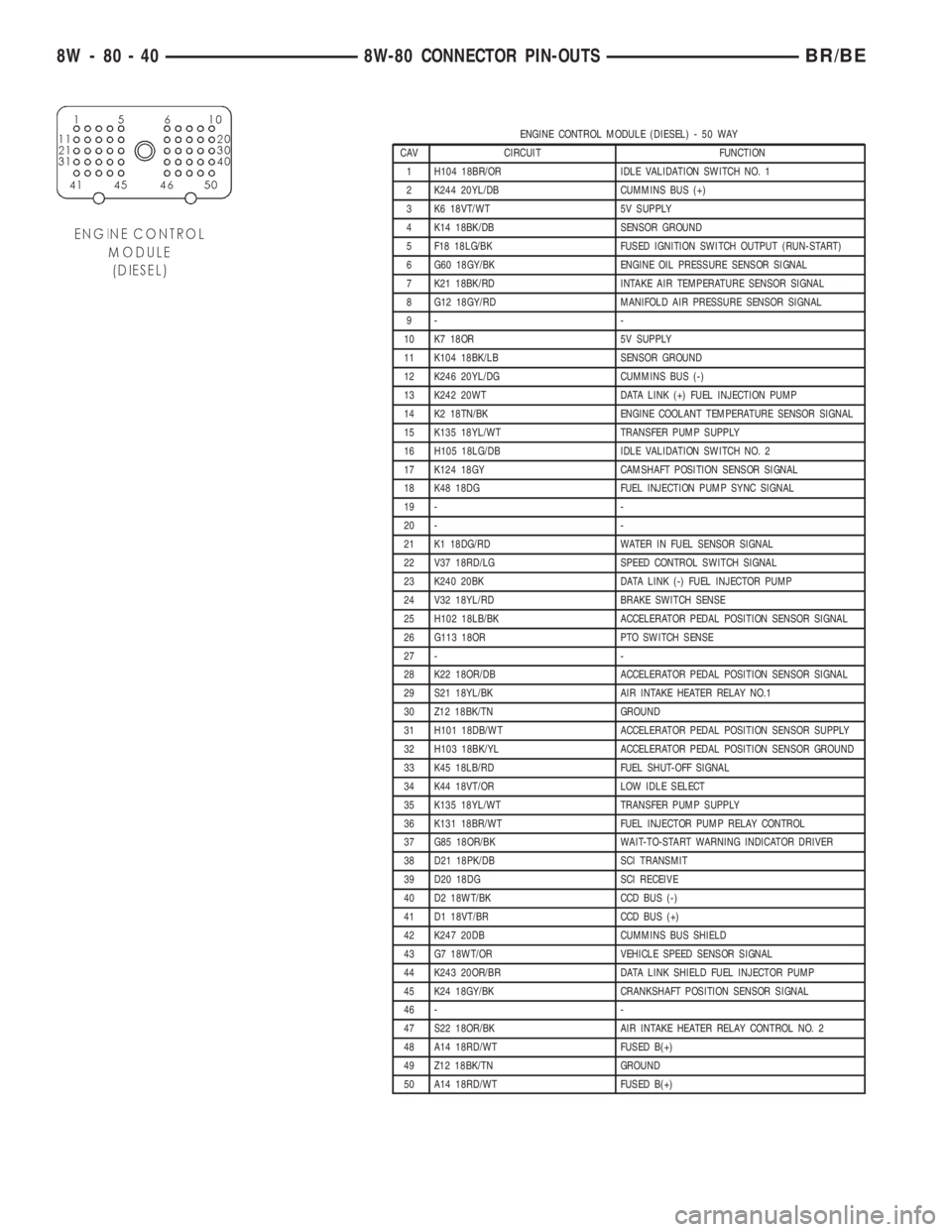
ENGINE CONTROL MODULE (DIESEL) - 50 WAY
CAV CIRCUIT FUNCTION
1 H104 18BR/OR IDLE VALIDATION SWITCH NO. 1
2 K244 20YL/DB CUMMINS BUS (+)
3 K6 18VT/WT 5V SUPPLY
4 K14 18BK/DB SENSOR GROUND
5 F18 18LG/BK FUSED IGNITION SWITCH OUTPUT (RUN-START)
6 G60 18GY/BK ENGINE OIL PRESSURE SENSOR SIGNAL
7 K21 18BK/RD INTAKE AIR TEMPERATURE SENSOR SIGNAL
8 G12 18GY/RD MANIFOLD AIR PRESSURE SENSOR SIGNAL
9- -
10 K7 18OR 5V SUPPLY
11 K104 18BK/LB SENSOR GROUND
12 K246 20YL/DG CUMMINS BUS (-)
13 K242 20WT DATA LINK (+) FUEL INJECTION PUMP
14 K2 18TN/BK ENGINE COOLANT TEMPERATURE SENSOR SIGNAL
15 K135 18YL/WT TRANSFER PUMP SUPPLY
16 H105 18LG/DB IDLE VALIDATION SWITCH NO. 2
17 K124 18GY CAMSHAFT POSITION SENSOR SIGNAL
18 K48 18DG FUEL INJECTION PUMP SYNC SIGNAL
19 - -
20 - -
21 K1 18DG/RD WATER IN FUEL SENSOR SIGNAL
22 V37 18RD/LG SPEED CONTROL SWITCH SIGNAL
23 K240 20BK DATA LINK (-) FUEL INJECTOR PUMP
24 V32 18YL/RD BRAKE SWITCH SENSE
25 H102 18LB/BK ACCELERATOR PEDAL POSITION SENSOR SIGNAL
26 G113 18OR PTO SWITCH SENSE
27 - -
28 K22 18OR/DB ACCELERATOR PEDAL POSITION SENSOR SIGNAL
29 S21 18YL/BK AIR INTAKE HEATER RELAY NO.1
30 Z12 18BK/TN GROUND
31 H101 18DB/WT ACCELERATOR PEDAL POSITION SENSOR SUPPLY
32 H103 18BK/YL ACCELERATOR PEDAL POSITION SENSOR GROUND
33 K45 18LB/RD FUEL SHUT-OFF SIGNAL
34 K44 18VT/OR LOW IDLE SELECT
35 K135 18YL/WT TRANSFER PUMP SUPPLY
36 K131 18BR/WT FUEL INJECTOR PUMP RELAY CONTROL
37 G85 18OR/BK WAIT-TO-START WARNING INDICATOR DRIVER
38 D21 18PK/DB SCI TRANSMIT
39 D20 18DG SCI RECEIVE
40 D2 18WT/BK CCD BUS (-)
41 D1 18VT/BR CCD BUS (+)
42 K247 20DB CUMMINS BUS SHIELD
43 G7 18WT/OR VEHICLE SPEED SENSOR SIGNAL
44 K243 20OR/BR DATA LINK SHIELD FUEL INJECTOR PUMP
45 K24 18GY/BK CRANKSHAFT POSITION SENSOR SIGNAL
46 - -
47 S22 18OR/BK AIR INTAKE HEATER RELAY CONTROL NO. 2
48 A14 18RD/WT FUSED B(+)
49 Z12 18BK/TN GROUND
50 A14 18RD/WT FUSED B(+)
8W - 80 - 40 8W-80 CONNECTOR PIN-OUTSBR/BE
Page 1080 of 2889

POWERTRAIN CONTROL MODULE C1 (GAS) - BLACK 32 WAY
CAV CIRCUIT FUNCTION
1 K32 18YL/GY (8.0L) IGNITION COIL NO. 4 DRIVER
2 F18 18LG/BK FUSED IGNITION SWITCH OUTPUT (RUN-START)
3 K18 18RD/BK (8.0L) IGNITION COIL NO. 3 DRIVER
4 K4 18BK/LB SENSOR GROUND
5 K43 18DG/GY (8.0L) IGNITION COIL NO. 5 DRIVER
6 T41 18BK/WT (A/T) PARK/NEUTRAL POSITION SWITCH SENSE
7 K19 16BK/GY (3.9L/5.2L/5.9L) IGNITION COIL NO. 1 DRIVER
7 K19 18BK/GY (8.0L) IGNITION COIL NO. 1 DRIVER
8 K24 18GY/BK CRANKSHAFT POSITION SENSOR SIGNAL
9 K17 18DB/WT (8.0L) IGNITION COIL NO. 2 DRIVER
10 K60 18YL/BK IDLE AIR CONTROL NO. 2 DRIVER
11 K40 18BR/WT IDLE AIR CONTROL NO. 3 DRIVER
12 - -
13 G113 18OR PTO SWITCH SENSE
14 - -
15 K21 18BK/RD INTAKE AIR TEMPERATURE SENSOR SIGNAL
16 K2 18TN/BK ENGINE COOLANT TEMPERATURE SENSOR SIGNAL
17 K6 18VT/WT 5V SUPPLY
18 K44 18TN/YL CAMSHAFT POSITION SENSOR SIGNAL
19 K39 18GY/RD IDLE AIR CONTROL NO. 1 DRIVER
20 K59 18VT/BK IDLE AIR CONTROL NO. 4 DRIVER
21 - -
22 A14 16RD/WT FUSED B(+)
23 K22 18OR/DB THROTTLE POSITION SENSOR SIGNAL
24 K141 18TN/WT (3.9L/5.2L/5.9L) (CALI-
FORNIA EXCEPT 8.0L)OXYGEN SENSOR 1/1 SIGNAL
24 K41 18BK/DG (5.9L HD/8.0L) OXYGEN SENSOR 1/1 SIGNAL
25 K341 18OR/BK (3.9L/5.2L) (CALIFOR-
NIA)OXYGEN SENSOR 1/2 SIGNAL
25 K341 18OR/BK (8.0L) OXYGEN SENSOR 1/3 SIGNAL
26 K241 18LG/RD (8.0L) (5.9L HD) OXYGEN SENSOR 2/1 SIGNAL
26 K241 18LG/RD (CALIFORNIA) OXYGEN SENSOR 2/1 SIGNAL
27 K1 18DG/RD MAP SENSOR SIGNAL
28 - -
29 K441 18OR/TN (CALIFORNIA) OXYGEN SENSOR 2/2 SIGNAL
29 K141 18TN/WT (8.0L) OXYGEN SENSOR 1/2 SIGNAL
30 - -
31 Z12 14BK/TN GROUND
32 Z12 14BK/TN GROUND
POWERTRAIN CONTROL MODULE C2 (DIESEL) - BLACK 32 WAY
CAV CIRCUIT FUNCTION
1 T54 18VT (A/T) TRANSMISSION TEMPERATURE SENSOR SIGNAL
2- -
3- -
4- -
5- -
6- -
7- -
8 K88 18VT/WT (A/T) GOVERNOR PRESSURE SOLENOID CONTROL
BR/BE8W-80 CONNECTOR PIN-OUTS 8W - 80 - 67
Page 1095 of 2889
Connector Name/Number Color Location Fig.
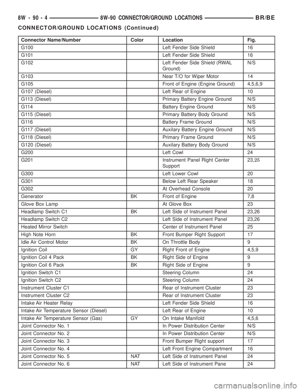
G100 Left Fender Side Shield 16
G101 Left Fender Side Shield 16
G102 Left Fender Side Shield (RWAL
Ground)N/S
G103 Near T/O for Wiper Motor 14
G105 Front of Engine (Engine Ground) 4,5,6,9
G107 (Diesel) Left Rear of Engine 10
G113 (Diesel) Primary Battery Engine Ground N/S
G114 Battery Engine Ground N/S
G115 (Diesel) Primary Battery Body Ground N/S
G116 Battery Frame Ground N/S
G117 (Diesel) Auxilary Battery Engine Ground N/S
G118 (Diesel) Primary Frame Ground N/S
G120 (Diesel) Auxilary Battery Body Ground N/S
G200 Left Cowl 24
G201 Instrument Panel Right Center
Support23,25
G300 Left Lower Cowl 20
G301 Below Left Rear Speaker 18
G302 At Overhead Console 20
Generator BK Front of Engine 7,8
Glove Box Lamp At Glove Box 23
Headlamp Switch C1 BK Left Side of Instrument Panel 23,26
Headlamp Switch C2 Left Side of Instrument Panel 23,26
Heated Mirror Switch Center of Instrument Panel 25
High Note Horn BK Front Bumper Right Support 17
Idle Air Control Motor BK On Throttle Body 9
Ignition Coil GY Right Front of Engine 4,5,9
Ignition Coil 4 Pack BK Right Side of Engine 9
Ignition Coil 6 Pack BK Right Side of Engine 9
Ignition Switch C1 Steering Column 24
Ignition Switch C2 Steering Column 24
Instrument Cluster C1 Rear of Instrument Cluster 23
Instrument Cluster C2 Rear of Instrument Cluster 23
Intake Air Heater Relay Left Fender Side Shield 16
Intake Air Temperature Sensor (Diesel) Left Rear of Engine 10
Intake Air Temperature Sensor (Gas) GY On Intake Manifold 4,5,6
Joint Connector No. 1 In Power Distribution Center N/S
Joint Connector No. 2 In Power Distribution Center N/S
Joint Connector No. 3 Front Bumper Right support 17
Joint Connector No. 4 Left Front Engine Compartment 16
Joint Connector No. 5 NAT Left Side of Instrument Panel 24
Joint Connector No. 6 NAT Left Side of Instrument Pane 24
8W - 90 - 4 8W-90 CONNECTOR/GROUND LOCATIONSBR/BE
CONNECTOR/GROUND LOCATIONS (Continued)
Page 1535 of 2889
WARNING: THE EXHAUST MANIFOLD, EXHAUST
PIPES AND CATALYTIC CONVERTER BECOME
VERY HOT DURING ENGINE OPERATION. ALLOW
ENGINE TO COOL BEFORE REMOVING OXYGEN
SENSOR.
(1) Raise and support the vehicle.
(2) Disconnect the wire connector from the O2S
sensor.
CAUTION: When disconnecting the sensor electrical
connector, do not pull directly on wire going into
sensor.
(3) Remove the O2S sensor with an oxygen sensor
removal and installation tool.
INSTALLATION
Threads of new oxygen sensors are factory coated
with anti-seize compound to aid in removal.DO
NOT add any additional anti-seize compound to
the threads of a new oxygen sensor.
(1) Install the O2S sensor. Tighten to 30 N´m (22
ft. lbs.) torque.
(2) Connect the O2S sensor wire connector.
(3) Lower the vehicle.
PTO SWITCH
DESCRIPTION
This Powertrain Control Module (PCM) input is
used only on models equipped with aftermarket
Power Take Off (PTO) units.
OPERATION
The input is used only to tell the PCM that the
PTO has been engaged. The PCM will disable (tem-
porarily shut down) certain OBD II diagnostic trou-
ble codes when the PTO is engaged.
When the aftermarket PTO switch has been
engaged, a 12V + signal is sent through circuit G113
to PCM pin A13. The PCM will then sense and deter-
mine that the PTO has been activated.
THROTTLE BODY
DESCRIPTION
The throttle body is located on the intake manifold.
Fuel does not enter the intake manifold through the
throttle body. Fuel is sprayed into the manifold by
the fuel injectors.
OPERATION
Filtered air from the air cleaner enters the intake
manifold through the throttle body. The throttle body
contains an air control passage controlled by an Idle
Air Control (IAC) motor. The air control passage is
used to supply air for idle conditions. A throttle valve
(plate) is used to supply air for above idle conditions.
Certain sensors are attached to the throttle body.
The accelerator pedal cable, speed control cable and
transmission control cable (when equipped) are con-
nected to the throttle body linkage arm.
A (factory adjusted) set screw is used to mechani-
cally limit the position of the throttle body throttle
plate.Never attempt to adjust the engine idle
speed using this screw.All idle speed functions are
controlled by the PCM.
REMOVAL - 3.9L/5.2L/5.9L
A (factory adjusted) set screw is used to mechani-
cally limit the position of the throttle body throttle
plate.Never attempt to adjust the engine idle
speed using this screw.All idle speed functions are
controlled by the powertrain control module (PCM).
(1) Remove the air cleaner.
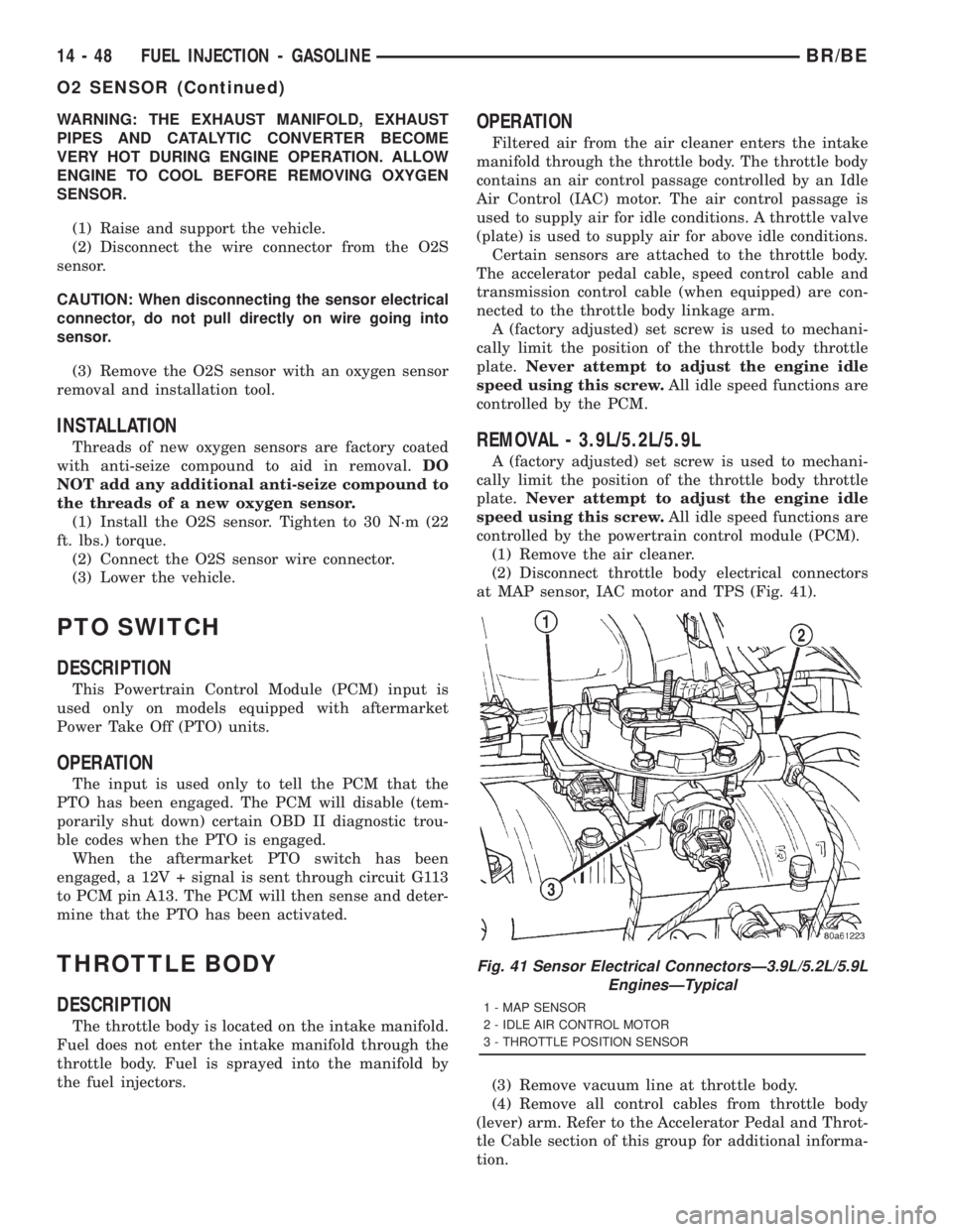
(2) Disconnect throttle body electrical connectors
at MAP sensor, IAC motor and TPS (Fig. 41).
(3) Remove vacuum line at throttle body.
(4) Remove all control cables from throttle body
(lever) arm. Refer to the Accelerator Pedal and Throt-
tle Cable section of this group for additional informa-
tion.
Fig. 41 Sensor Electrical ConnectorsÐ3.9L/5.2L/5.9L
EnginesÐTypical
1 - MAP SENSOR
2 - IDLE AIR CONTROL MOTOR
3 - THROTTLE POSITION SENSOR
14 - 48 FUEL INJECTION - GASOLINEBR/BE
O2 SENSOR (Continued)