CD player DODGE RAM 2001 Service Repair Manual
[x] Cancel search | Manufacturer: DODGE, Model Year: 2001, Model line: RAM, Model: DODGE RAM 2001Pages: 2889, PDF Size: 68.07 MB
Page 427 of 2889

Audio System Diagnosis
CONDITION POSSIBLE CAUSE CORRECTION
NO/POOR TAPE
OPERATION1. Faulty tape. 1. Insert known good tape and test operation.
2. Foreign objects behind
tape door.2. Remove foreign objects and test operation.
3. Dirty cassette tape
head.3. Clean head with Mopar Cassette Head Cleaner.
4. Faulty tape deck. 4. Exchange or replace radio, if required.
NO COMPACT DISC
OPERATION1. Faulty CD. 1. Insert known good CD and test operation.
2. Foreign material on
CD.2. Clean CD and test operation.
3. Condensation on CD
or optics.3. Allow temperature of vehicle interior to stabilize and test
operation.
4. Faulty CD player. 4. Exchange or replace radio, if required.
SPECIAL TOOLS
AUDIO SYSTEMS
ANTENNA BODY & CABLE
DESCRIPTION
The antenna body and cable are not readily visible
in their installed positions in the vehicle. The most
visible component of the antenna body and cable are
the antenna adapter and the antenna cap nut, which
are located on the top of the right front fender panel
of the vehicle, near the right end of the cowl plenum.
The antenna body and cable are secured below the
fender panel by the antenna cap nut through a pre-
fabricated and dedicated mounting hole in the top of
the right front fender. The primary coaxial antenna
cable is then routed beneath the fender sheet metal
and through a prefabricated and dedicated cable
entry hole in the right cowl side panel into the inte-
rior of the vehicle. Inside the vehicle, the primary
coaxial cable is connected to a secondary instrument
panel antenna coaxial cable with an in-line connector
that is located behind the right end of the instrumentpanel. The secondary coaxial cable is then routed
behind the instrument panel to the back of the radio.
The factory-installed radio antenna body and cable
consists of the following components:
²Antenna adapter- The antenna adapter is
sometimes also referred to as the antenna bezel or
escutcheon.
²Antenna body- The die cast white metal
antenna body is the mating structure between the
antenna mast and the primary antenna coaxial cable.
²Antenna cable- This vehicle uses a two-piece
antenna coaxial cable. The primary antenna cable is
integral to the antenna body, and the secondary
antenna cable connects the primary cable to the
radio.
²Antenna cap nut- The antenna cap nut is a
special, bright-plated threaded fastener that captures
the antenna adapter and retains the antenna body to
the fender sheet metal.
The components of the radio antenna body and
cable cannot be adjusted or repaired. All factory-in-
stalled radios automatically compensate for radio
antenna trim. Therefore, no antenna trimmer adjust-
ment is required or possible after replacing the
antenna body and cable or the radio. If an antenna
body and cable component is damaged or faulty, it
must be replaced. Other than the primary antenna
cable, which is integral to the antenna body, the indi-
vidual components of the antenna are available for
service replacement.
OPERATION
The antenna body and cable connects the antenna
mast to the radio. The radio antenna is an electro-
magnetic circuit component used to capture radio fre-
quency signals that are broadcast by local
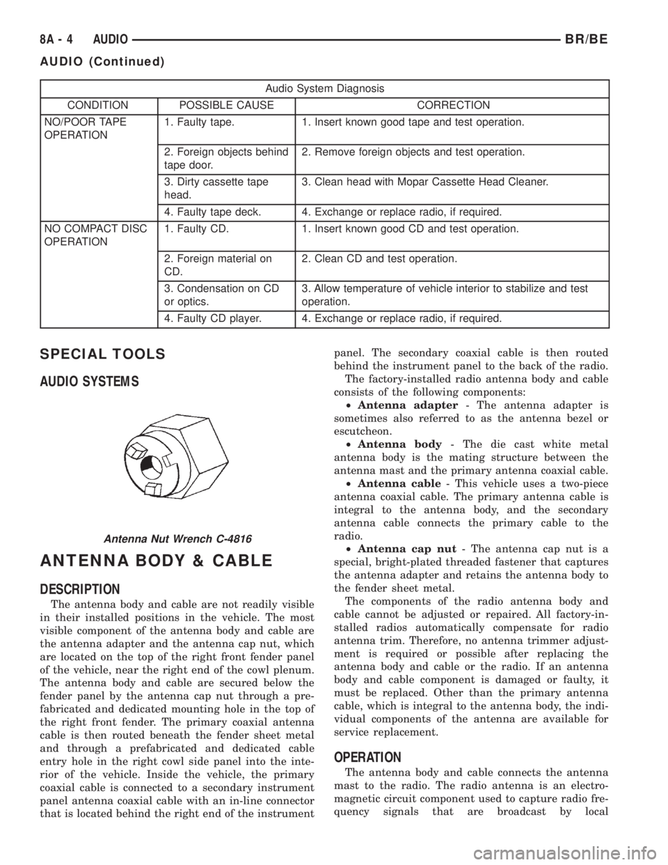
Antenna Nut Wrench C-4816
8A - 4 AUDIOBR/BE
AUDIO (Continued)
Page 434 of 2889

²Radio memory presets not working properly
²Volume changes with no remote radio switch
input
²Remote radio switch buttons taking on other
functions
²CD player skipping tracks
²Remote radio switch inoperative.
For complete circuit diagrams, refer to the appro-
priate wiring information. The wiring information
includes wiring diagrams, proper wire and connector
repair procedures, details of wire harness routing
and retention, connector pin-out information and
location views for the various wire harness connec-
tors, splices and grounds.
WARNING: ON VEHICLES EQUIPPED WITH AIR-
BAGS, REFER TO ELECTRICAL, RESTRAINTS
BEFORE ATTEMPTING ANY STEERING WHEEL,
STEERING COLUMN, OR INSTRUMENT PANEL
COMPONENT DIAGNOSIS OR SERVICE. FAILURE
TO TAKE THE PROPER PRECAUTIONS COULD
RESULT IN ACCIDENTAL AIRBAG DEPLOYMENT
AND POSSIBLE PERSONAL INJURY.
CAUTION: The speaker output of the radio receiver
is a ªfloating groundº system. Do not allow any
speaker lead to short to ground, as damage to the
radio receiver may result.
(1) Check the fused B(+) fuse in the junction block.
If OK, go to Step 2. If not OK, repair the shorted cir-
cuit or component as required and replace the faulty
fuse.
(2) Check for battery voltage at the fused B(+) fuse
in the junction block. If OK, go to Step 3. If not OK,
repair the open fused B(+) circuit to the Power Dis-
tribution Center (PDC) as required.
(3) Check the fused ignition switch output (acc/
run) fuse in the junction block. If OK, go to Step 4. If
not OK, repair the shorted circuit or component as
required and replace the faulty fuse(s).
(4) Turn the ignition switch to the On position.
Check for battery voltage at the fused ignition switch
output (acc/run) fuse in the junction block. If OK, go
to Step 5. If not OK, repair the open fused ignition
switch output (acc/run) circuit to the ignition switch
as required.
(5) Turn the ignition switch to the Off position.
Disconnect and isolate the battery negative cable.
Remove the radio receiver from the instrument
panel, but do not disconnect the wire harness connec-
tors. Check for continuity between the radio receiver
chassis and a good ground. There should be continu-
ity. If OK, go to Step 6. If not OK, repair the open
ground circuit to ground as required.(6) Connect the battery negative cable. Turn the
ignition switch to the On position. Check for battery
voltage at the fused ignition switch output (acc/run)
circuit cavity of the left (gray) radio wire harness
connector. If OK, go to Step 7. If not OK, repair the
open fused ignition switch output (acc/run) circuit to
the junction block fuse as required.
(7) Turn the ignition switch to the Off position.
Check for battery voltage at the fused B(+) circuit
cavity of the left (gray) radio wire harness connector.
If OK, replace the faulty radio receiver. If not OK,
repair the open fused B(+) circuit to the junction
block fuse as required.
REMOVAL
(1) Disconnect and isolate the battery negative
cable.
(2) Remove the cluster bezel from the instrument
panel.
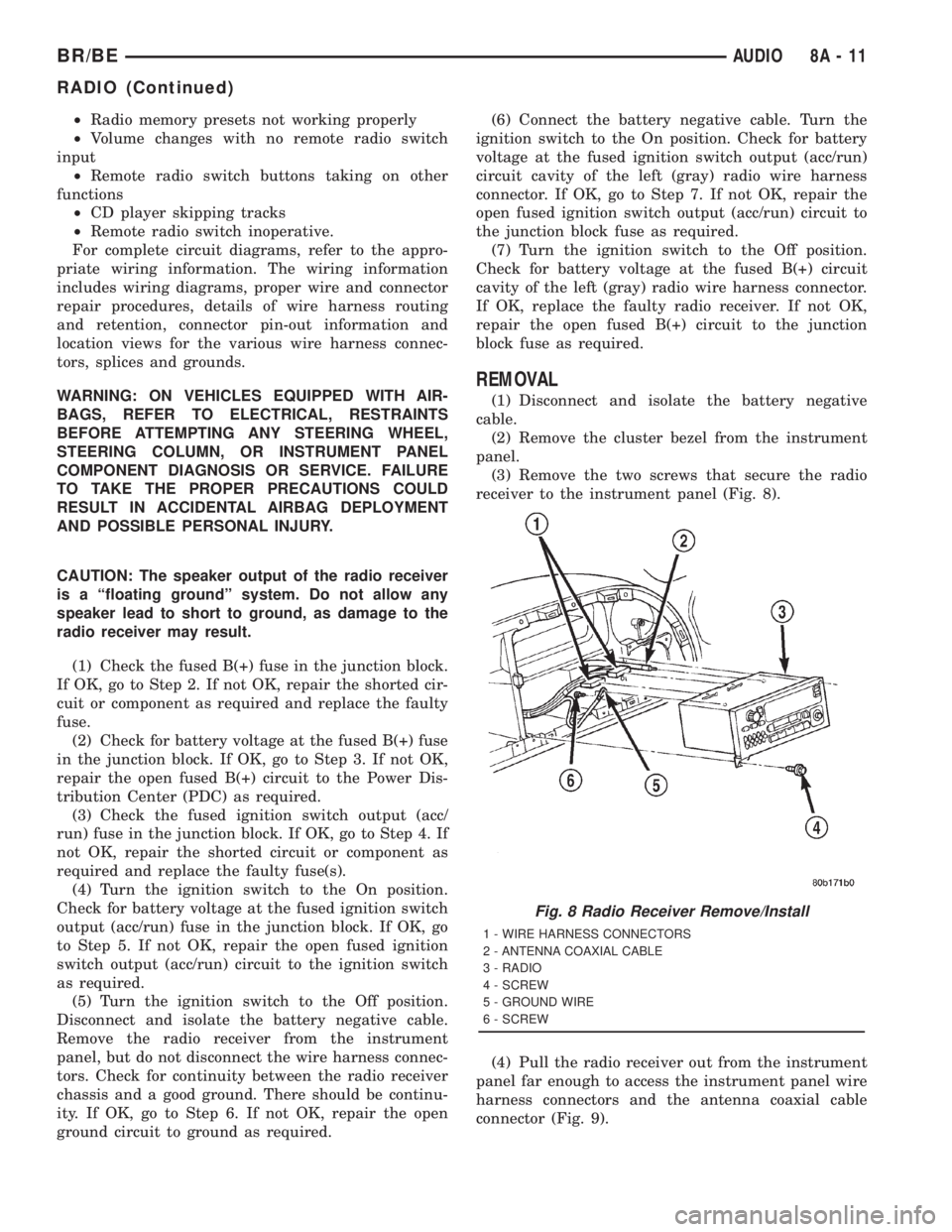
(3) Remove the two screws that secure the radio
receiver to the instrument panel (Fig. 8).
(4) Pull the radio receiver out from the instrument
panel far enough to access the instrument panel wire
harness connectors and the antenna coaxial cable
connector (Fig. 9).
Fig. 8 Radio Receiver Remove/Install
1 - WIRE HARNESS CONNECTORS
2 - ANTENNA COAXIAL CABLE
3 - RADIO
4 - SCREW
5 - GROUND WIRE
6 - SCREW
BR/BEAUDIO 8A - 11
RADIO (Continued)
Page 2840 of 2889

ROAD TEST
DESCRIPTION - ROAD TEST INSPECTION
The following items must be inspected during the
road test portion of the new vehicle inspection.
²Check neutral safety switch operation
²Check operation of shift/clutch interlock system
²Check operation of gauges and warning lights
²Check horn operation
²Check operation of turn signals and emergency
flashers
²Check all mirror adjustments, including day/
night function
²Check windshield wipers for proper wipe pattern
and intermittent mode (if equipped)
²Check washer spray pattern
²Check heater, defroster and air conditioning for
proper operation
²Check that the fan operates quietly
²Check the rear window defroster (if equipped)
²Leave air selection lever in the fresh air position
²Check the rear heater and air conditioning for
proper operation
²Check the rear air register locations
²Check that the indicator lamps operate properly
²Check the operation of the radio, cassette and/or
compact disc player, and that sound quality is good
²Ensure that the clock displays the correct time
²Check that the trip computer/maintenance
reminder operates in all modes
²Check all speed control functions
²Check the service brakes to ensure that they
stop the vehicle in a straight line, without noise,
shudder or vibration
²Check the brake warning light
²Check the parking brake operation
²Check the engine's performance
²Check the transmission's performance for
smooth, quiet operation. If the vehicle is a 4x4, check
that the transfer case shifts easily among all ranges
²Check Autostick function (if equipped)
²Check the vehicle's steering and handling
²The steering wheel should be centered when
traveling in a straight line
²The vehicle should not pull or vibrate
²Check for squeaks, rattles and wind noise
²Check any other vehicle aspects you believe are
important, but that may not be included on the New
Vehicle Preparation Form
²Fill fuel tank with specified grade of fuel
INSPECTION - FUEL
Fill fuel tank with specified grade of gasoline (reg-
ular, midgrade or premium).
INSPECTION - OTHER
As part of DaimlerChrysler's Customer One philos-
ophy, the ªOtherº blank is provided on the New Vehi-
cle Preparation Form. This is designed to encourage
you to check any aspects of vehicle operation that
you believe are important to your customers, but that
do not appear elsewhere on the form.
INSPECTION - SQUEAKS, RATTLES AND WIND
NOISE
(1) Make sure that the instrument panel, glove
box, seats, steering wheel and column are free from
squeaks and rattles. Tighten any obvious loose fas-
teners.
(2) Check that the windows and doors are free
from squeaks, rattles and wind noise.
(3) Check that the vehicle exterior is free from
squeaks, rattles and noise, front and rear.
(4) Make sure that all interior panels are free from
squeaks and rattles.
INSPECTION - STEERING AND HANDLING
(1) Check that the power assist works properly (if
equipped). Steering should not require excessive
effort.
(2) Make sure the steering wheel does not vibrate
at idle or road speed.
(3) Ensure that the steering wheel is centered
when traveling straight ahead.
(4) Check that the vehicle does not drift to one
side.
(5) Make sure that the vehicle does not vibrate/
shake.
INSPECTION - TRANSMISSION/TRANSFER
CASE
AUTOMATIC TRANSMISSION
(1) Make sure that the park lock holds the vehicle
With the vehicle on a grade, put automatic trans-
mission in PARK and slowly release the service
brake to see if park lock holds. If it does not hold, the
transmission requires further service.
(2) Make sure shift lever operates easily/ smoothly
(Fig. 36).
Check for smooth shifting. Check for proper
upshifting and downshifting.
MANUAL TRANSMISSION
(1) Check that the shifter operates easily (Fig. 38).
(2) Make sure that the clutch operates smoothly
(Fig. 37).
(3) Look for proper synchronization.
The gears should not grind.
BR/BENEW VEHICLE PREPARATION 30 - 15
Page 2842 of 2889

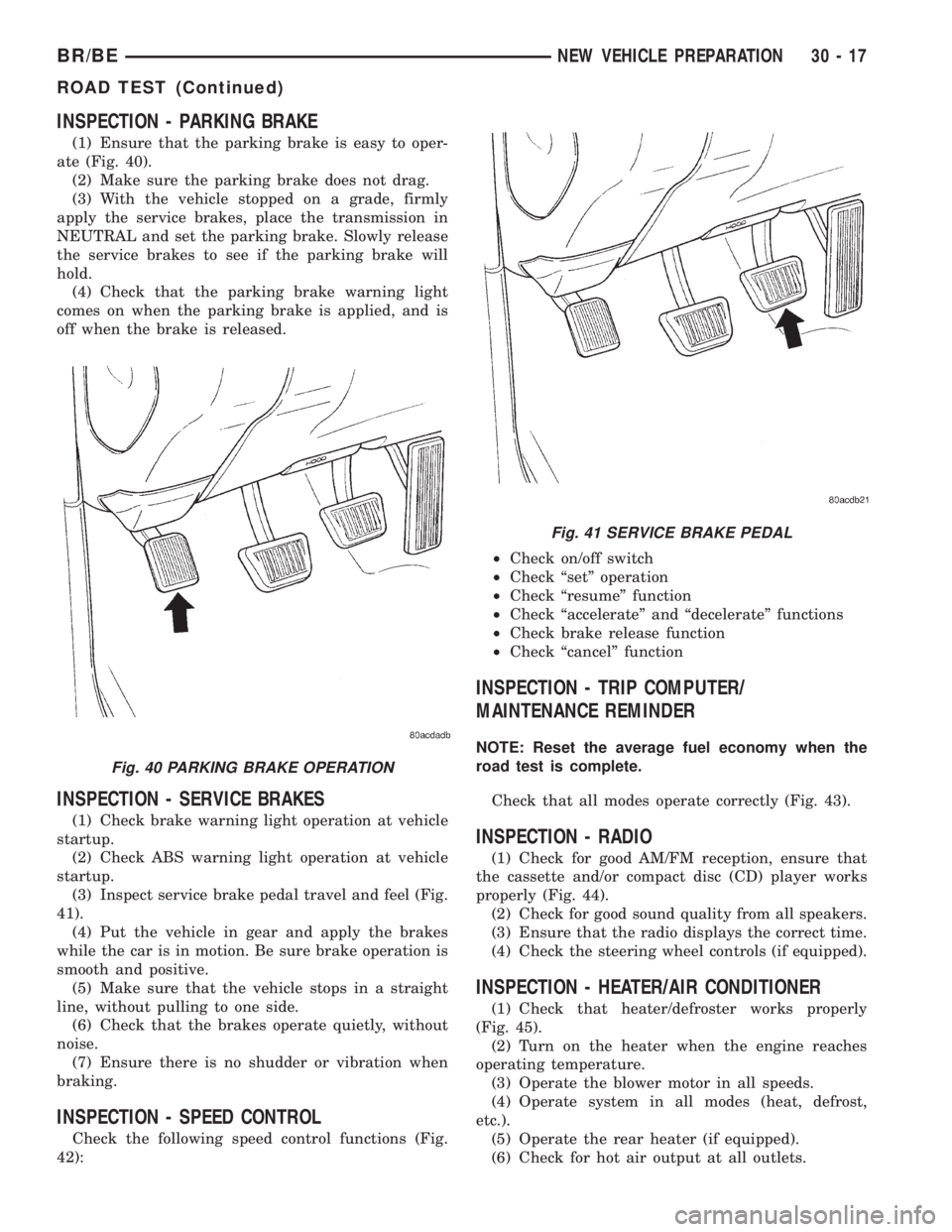
INSPECTION - PARKING BRAKE
(1) Ensure that the parking brake is easy to oper-
ate (Fig. 40).
(2) Make sure the parking brake does not drag.
(3) With the vehicle stopped on a grade, firmly
apply the service brakes, place the transmission in
NEUTRAL and set the parking brake. Slowly release
the service brakes to see if the parking brake will
hold.
(4) Check that the parking brake warning light
comes on when the parking brake is applied, and is
off when the brake is released.
INSPECTION - SERVICE BRAKES
(1) Check brake warning light operation at vehicle
startup.
(2) Check ABS warning light operation at vehicle
startup.
(3) Inspect service brake pedal travel and feel (Fig.
41).
(4) Put the vehicle in gear and apply the brakes
while the car is in motion. Be sure brake operation is
smooth and positive.
(5) Make sure that the vehicle stops in a straight
line, without pulling to one side.
(6) Check that the brakes operate quietly, without
noise.
(7) Ensure there is no shudder or vibration when
braking.
INSPECTION - SPEED CONTROL
Check the following speed control functions (Fig.
42):²Check on/off switch
²Check ªsetº operation
²Check ªresumeº function
²Check ªaccelerateº and ªdecelerateº functions
²Check brake release function
²Check ªcancelº function
INSPECTION - TRIP COMPUTER/
MAINTENANCE REMINDER
NOTE: Reset the average fuel economy when the
road test is complete.
Check that all modes operate correctly (Fig. 43).
INSPECTION - RADIO
(1) Check for good AM/FM reception, ensure that
the cassette and/or compact disc (CD) player works
properly (Fig. 44).
(2) Check for good sound quality from all speakers.
(3) Ensure that the radio displays the correct time.
(4) Check the steering wheel controls (if equipped).
INSPECTION - HEATER/AIR CONDITIONER
(1) Check that heater/defroster works properly
(Fig. 45).
(2) Turn on the heater when the engine reaches
operating temperature.
(3) Operate the blower motor in all speeds.
(4) Operate system in all modes (heat, defrost,
etc.).
(5) Operate the rear heater (if equipped).
(6) Check for hot air output at all outlets.
Fig. 40 PARKING BRAKE OPERATION
Fig. 41 SERVICE BRAKE PEDAL
BR/BENEW VEHICLE PREPARATION 30 - 17
ROAD TEST (Continued)