roof rack DODGE RAM 2001 Service Repair Manual
[x] Cancel search | Manufacturer: DODGE, Model Year: 2001, Model line: RAM, Model: DODGE RAM 2001Pages: 2889, PDF Size: 68.07 MB
Page 601 of 2889
(9) Disconnect the instrument panel wire harness
connector for the multi-function switch from the
switch connector receptacle. Check for continuity
between the hazard flasher signal circuit cavities in
the JB receptacle for the combination flasher and the
instrument panel wire harness connector for the
multi-function switch. There should be continuity. If
OK, go to Step 10. If not OK, repair the open hazard
flasher signal circuit between the JB and the multi-
function switch as required.
(10) Check for continuity between the flasher out-
put circuit cavities of the JB receptacle for the com-
bination flasher and in the instrument panel wire
harness connector for the multi-function switch.
There should be continuity. If OK, test the multi-
function switch. (Refer to 8 - ELECTRICAL/LAMPS/
LIGHTING - EXTERIOR/MULTI-FUNCTION
SWITCH - DIAGNOSIS AND TESTING). If not OK,
repair the open flasher output circuit between the JB
and the multi-function switch as required.
SPECIFICATIONS
EXTERIOR LAMPS
LAMP BULB
Back-up 3157
Cargo 921
Center High Mounted
Stop921
Clearance Roof Mounted 168
Fog Lamps 896
Headlamp - SLT 9004LL
Headlamp - Sport Low
Beam9007
Headlamp - Sport High
Beam9004LL
License Plate w/o
Bumper1155
License Plate -Step
Bumper168
Park/Turn Signal 3157NA
Snow Plow Control 161
Tail/Brake/Turn Signal 3157
Tail/Brake/Cab - Chassis 1157
Underhood 105
SPECIAL TOOLS
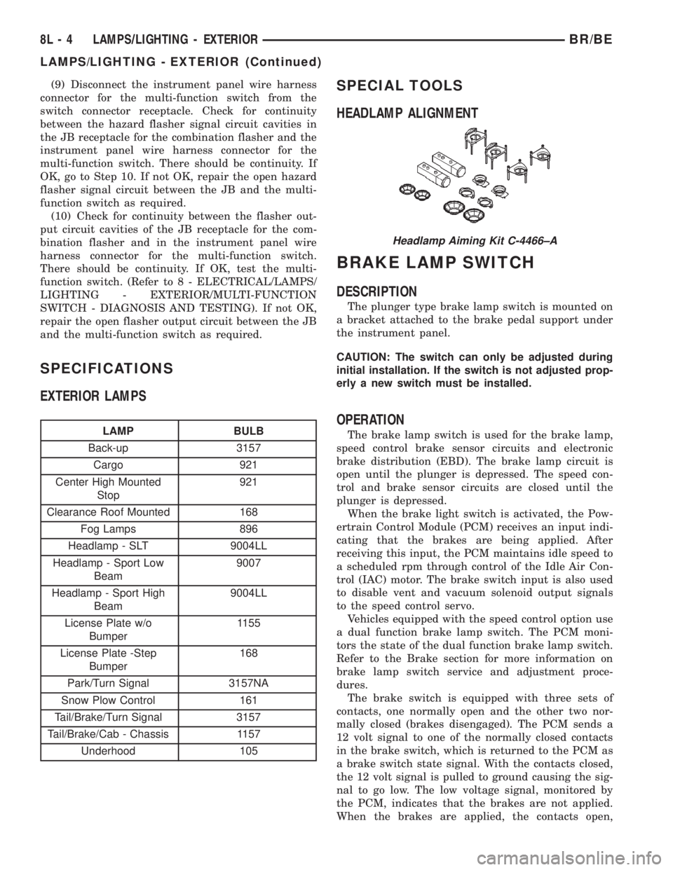
HEADLAMP ALIGNMENT
BRAKE LAMP SWITCH
DESCRIPTION
The plunger type brake lamp switch is mounted on
a bracket attached to the brake pedal support under
the instrument panel.
CAUTION: The switch can only be adjusted during
initial installation. If the switch is not adjusted prop-
erly a new switch must be installed.
OPERATION
The brake lamp switch is used for the brake lamp,
speed control brake sensor circuits and electronic
brake distribution (EBD). The brake lamp circuit is
open until the plunger is depressed. The speed con-
trol and brake sensor circuits are closed until the
plunger is depressed.
When the brake light switch is activated, the Pow-
ertrain Control Module (PCM) receives an input indi-
cating that the brakes are being applied. After
receiving this input, the PCM maintains idle speed to
a scheduled rpm through control of the Idle Air Con-
trol (IAC) motor. The brake switch input is also used
to disable vent and vacuum solenoid output signals
to the speed control servo.
Vehicles equipped with the speed control option use
a dual function brake lamp switch. The PCM moni-
tors the state of the dual function brake lamp switch.
Refer to the Brake section for more information on
brake lamp switch service and adjustment proce-
dures.
The brake switch is equipped with three sets of
contacts, one normally open and the other two nor-
mally closed (brakes disengaged). The PCM sends a
12 volt signal to one of the normally closed contacts
in the brake switch, which is returned to the PCM as
a brake switch state signal. With the contacts closed,
the 12 volt signal is pulled to ground causing the sig-
nal to go low. The low voltage signal, monitored by
the PCM, indicates that the brakes are not applied.
When the brakes are applied, the contacts open,
Headlamp Aiming Kit C-4466±A
8L - 4 LAMPS/LIGHTING - EXTERIORBR/BE
LAMPS/LIGHTING - EXTERIOR (Continued)
Page 603 of 2889
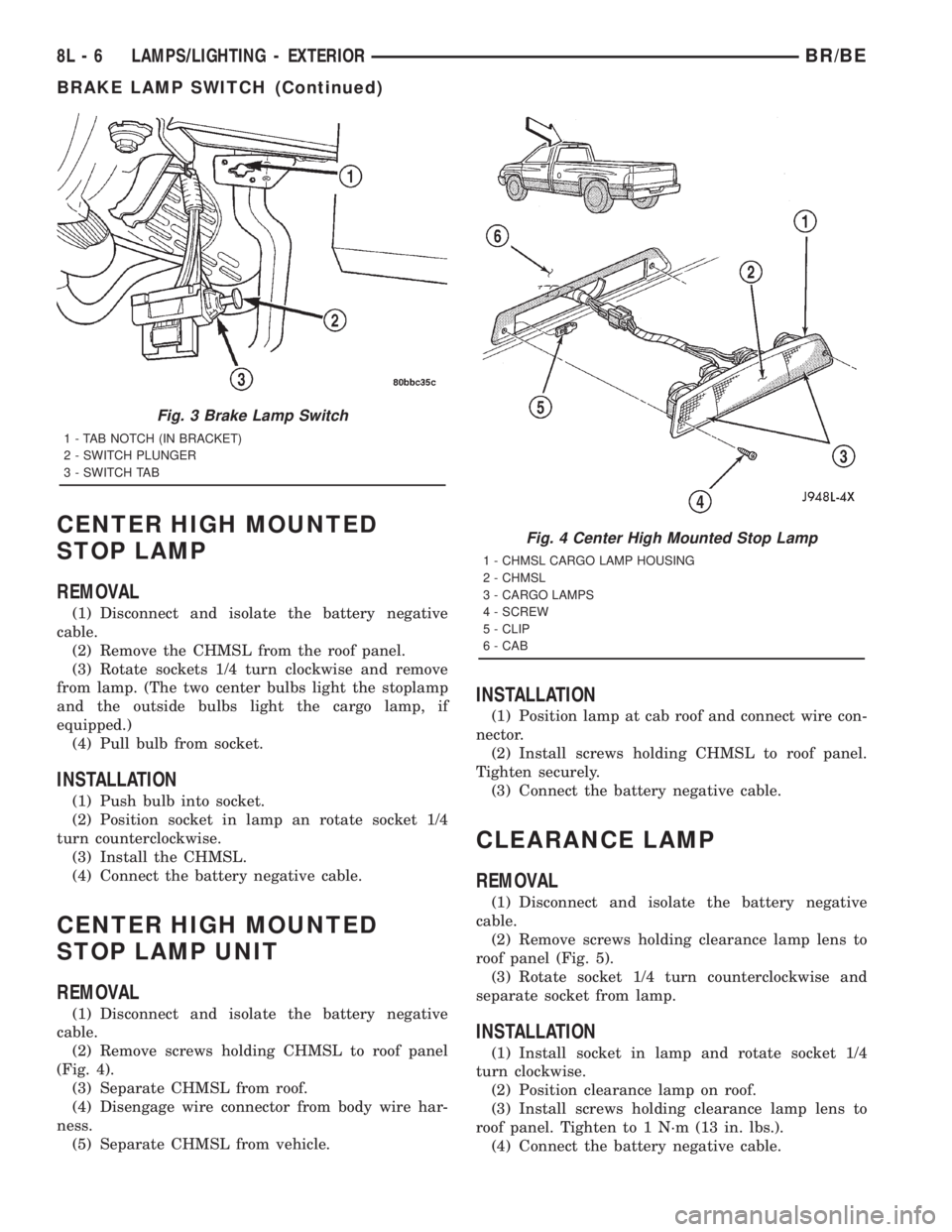
CENTER HIGH MOUNTED
STOP LAMP
REMOVAL
(1) Disconnect and isolate the battery negative
cable.
(2) Remove the CHMSL from the roof panel.
(3) Rotate sockets 1/4 turn clockwise and remove
from lamp. (The two center bulbs light the stoplamp
and the outside bulbs light the cargo lamp, if
equipped.)
(4) Pull bulb from socket.
INSTALLATION
(1) Push bulb into socket.
(2) Position socket in lamp an rotate socket 1/4
turn counterclockwise.
(3) Install the CHMSL.
(4) Connect the battery negative cable.
CENTER HIGH MOUNTED
STOP LAMP UNIT
REMOVAL
(1) Disconnect and isolate the battery negative
cable.
(2) Remove screws holding CHMSL to roof panel
(Fig. 4).
(3) Separate CHMSL from roof.
(4) Disengage wire connector from body wire har-
ness.
(5) Separate CHMSL from vehicle.
INSTALLATION
(1) Position lamp at cab roof and connect wire con-
nector.
(2) Install screws holding CHMSL to roof panel.
Tighten securely.
(3) Connect the battery negative cable.
CLEARANCE LAMP
REMOVAL
(1) Disconnect and isolate the battery negative
cable.
(2) Remove screws holding clearance lamp lens to
roof panel (Fig. 5).
(3) Rotate socket 1/4 turn counterclockwise and
separate socket from lamp.
INSTALLATION
(1) Install socket in lamp and rotate socket 1/4
turn clockwise.
(2) Position clearance lamp on roof.
(3) Install screws holding clearance lamp lens to
roof panel. Tighten to 1 N´m (13 in. lbs.).
(4) Connect the battery negative cable.
Fig. 3 Brake Lamp Switch
1 - TAB NOTCH (IN BRACKET)
2 - SWITCH PLUNGER
3 - SWITCH TAB
Fig. 4 Center High Mounted Stop Lamp
1 - CHMSL CARGO LAMP HOUSING
2 - CHMSL
3 - CARGO LAMPS
4 - SCREW
5 - CLIP
6 - CAB
8L - 6 LAMPS/LIGHTING - EXTERIORBR/BE
BRAKE LAMP SWITCH (Continued)
Page 624 of 2889
(3) If the multi-function switch fails any of the
continuity or resistance tests, replace the faulty
switch unit as required.
REMOVAL
WARNING: ON VEHICLES EQUIPPED WITH AIR-
BAGS, DISABLE THE AIRBAG SYSTEM BEFORE
ATTEMPTING ANY STEERING WHEEL, STEERING
COLUMN, OR INSTRUMENT PANEL COMPONENT
DIAGNOSIS OR SERVICE. DISCONNECT AND ISO-
LATE THE BATTERY NEGATIVE (GROUND) CABLE,
THEN WAIT TWO MINUTES FOR THE AIRBAG SYS-
TEM CAPACITOR TO DISCHARGE BEFORE PER-
FORMING FURTHER DIAGNOSIS OR SERVICE. THIS
IS THE ONLY SURE WAY TO DISABLE THE AIRBAG
SYSTEM. FAILURE TO TAKE THE PROPER PRE-
CAUTIONS COULD RESULT IN ACCIDENTAL AIR-
BAG DEPLOYMENT AND POSSIBLE PERSONAL
INJURY.
(1) Disconnect and isolate the battery negative
cable.
(2) If the vehicle is so equipped, unscrew the lever
from the tilt steering column adjuster mechanism
located on the left side of the column just below the
multi-function switch control stalk. Turn the lever
counterclockwise to unscrew it from the adjuster.
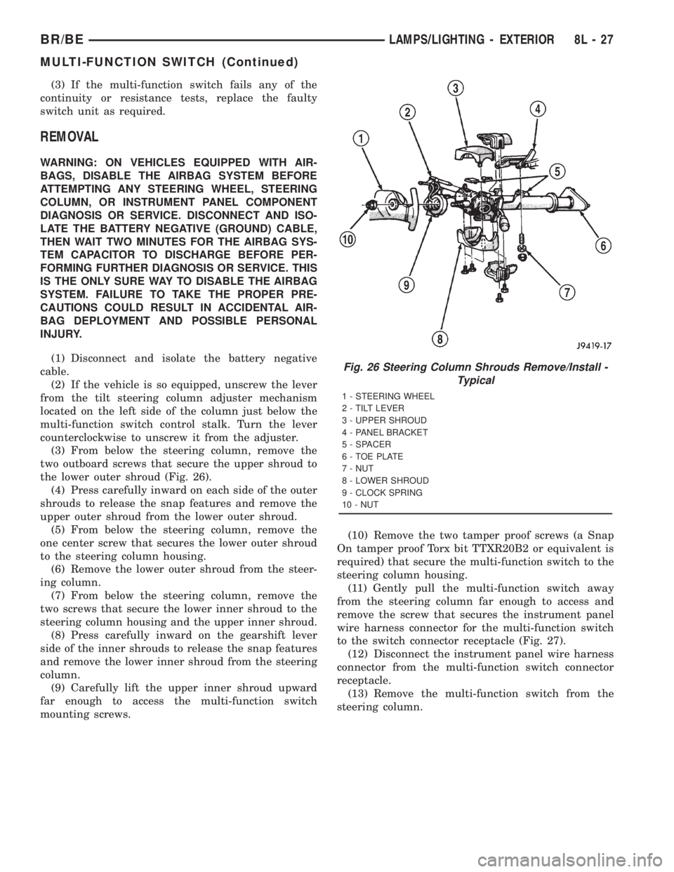
(3) From below the steering column, remove the
two outboard screws that secure the upper shroud to
the lower outer shroud (Fig. 26).
(4) Press carefully inward on each side of the outer
shrouds to release the snap features and remove the
upper outer shroud from the lower outer shroud.
(5) From below the steering column, remove the
one center screw that secures the lower outer shroud
to the steering column housing.
(6) Remove the lower outer shroud from the steer-
ing column.
(7) From below the steering column, remove the
two screws that secure the lower inner shroud to the
steering column housing and the upper inner shroud.
(8) Press carefully inward on the gearshift lever
side of the inner shrouds to release the snap features
and remove the lower inner shroud from the steering
column.
(9) Carefully lift the upper inner shroud upward
far enough to access the multi-function switch
mounting screws.(10) Remove the two tamper proof screws (a Snap
On tamper proof Torx bit TTXR20B2 or equivalent is
required) that secure the multi-function switch to the
steering column housing.
(11) Gently pull the multi-function switch away
from the steering column far enough to access and
remove the screw that secures the instrument panel
wire harness connector for the multi-function switch
to the switch connector receptacle (Fig. 27).
(12) Disconnect the instrument panel wire harness
connector from the multi-function switch connector
receptacle.
(13) Remove the multi-function switch from the
steering column.
Fig. 26 Steering Column Shrouds Remove/Install -
Typical
1 - STEERING WHEEL
2 - TILT LEVER
3 - UPPER SHROUD
4 - PANEL BRACKET
5 - SPACER
6 - TOE PLATE
7 - NUT
8 - LOWER SHROUD
9 - CLOCK SPRING
10 - NUT
BR/BELAMPS/LIGHTING - EXTERIOR 8L - 27
MULTI-FUNCTION SWITCH (Continued)
Page 647 of 2889
DIAGNOSIS & TESTING - AMBIENT
TEMPERATURE SENSOR
The thermometer function is supported by the
ambient temperature sensor, a wiring circuit, and a
portion of the compass mini-trip computer module. If
any portion of the ambient temperature sensor cir-
cuit fails, the compass/thermometer display function
will self-diagnose the circuit. If 55É C (131É F)
appears in the display, the sensor is being exposed to
temperatures above 55É C (131É F), or the sensor cir-
cuit is shorted. If ±40É C (±40É F) appears in the dis-
play, the sensor is being exposed to temperatures
below ±40É C (±40É F), or the sensor circuit is open.
The ambient temperature sensor circuit can also be
diagnosed using the following Sensor Test, and Sen-
sor Circuit Test. If the temperature sensor and cir-
cuit are confirmed to be OK, but the temperature
display is inoperative or incorrect, refer toCompass
Mini-Trip Computerin the Diagnosis and Testing
section of this group. For complete circuit diagrams,
refer toOverhead Consolein the Contents of Wir-
ing Diagrams.
SENSOR TEST
(1) Turn the ignition switch to the Off position.
Disconnect and isolate the battery negative cable.
Disconnect the ambient temperature sensor wire har-
ness connector.
(2) Measure the resistance of the ambient temper-
ature sensor. At ±40É C (±40É F), the sensor resis-
tance is 336 kilohms. At 55É C (131É F), the sensor
resistance is 2.488 kilohms. The sensor resistance
should read between these two values. If OK, refer to
Sensor Circuit Testin the Diagnosis and Testing
section of this group. If not OK, replace the faulty
ambient temperature sensor.
SENSOR CIRCUIT TEST
(1) Turn the ignition switch to the Off position.
Disconnect and isolate the battery negative cable.
Disconnect the ambient temperature sensor wire har-
ness connector and the overhead console wire har-
ness connector.
(2) Connect a jumper wire between the two termi-
nals in the body half of the ambient temperature sen-
sor wire harness connector.
(3) Check for continuity between the sensor return
circuit and the ambient temperature sensor signal
circuit cavities of the roof wire harness overhead con-
sole connector. There should be continuity. If OK, go
to Step 4. If not OK, repair the open sensor return
circuit or ambient temperature sensor signal circuit
to the ambient temperature sensor as required.(4) Remove the jumper wire from the body half of
the ambient temperature sensor wire harness con-
nector. Check for continuity between the sensor
return circuit cavity of the roof wire harness over-
head console connector and a good ground. There
should be no continuity. If OK, go to Step 5. If not
OK, repair the shorted sensor return circuit as
required.
(5) Check for continuity between the ambient tem-
perature sensor signal circuit cavity of the roof wire
harness overhead console connector and a good
ground. There should be no continuity. If OK, refer to
Compass Mini-Trip Computerin the Diagnosis
and Testing section of this group. If not OK, repair
the shorted ambient temperature sensor signal cir-
cuit as required.
REMOVAL
(1) Disconnect and isolate the battery negative
cable.
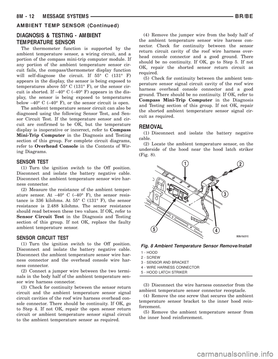
(2) Locate the ambient temperature sensor, on the
underside of the hood near the hood latch striker
(Fig. 8).
(3) Disconnect the wire harness connector from the
ambient temperature sensor connector receptacle.
(4) Remove the one screw that secures the ambient
temperature sensor bracket to the inner hood rein-
forcement.
(5) Remove the ambient temperature sensor from
the inner hood reinforcement.
Fig. 8 Ambient Temperature Sensor Remove/Install
1 - HOOD
2 - SCREW
3 - SENSOR AND BRACKET
4 - WIRE HARNESS CONNECTOR
5 - HOOD LATCH STRIKER
8M - 12 MESSAGE SYSTEMSBR/BE
AMBIENT TEMP SENSOR (Continued)
Page 1370 of 2889
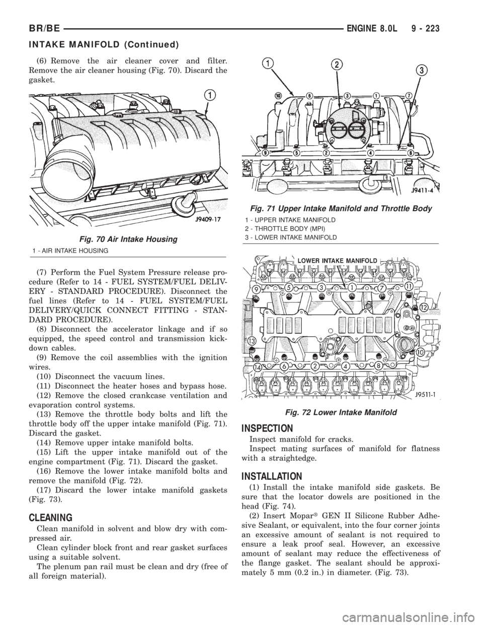
(6) Remove the air cleaner cover and filter.
Remove the air cleaner housing (Fig. 70). Discard the
gasket.
(7) Perform the Fuel System Pressure release pro-
cedure (Refer to 14 - FUEL SYSTEM/FUEL DELIV-
ERY - STANDARD PROCEDURE). Disconnect the
fuel lines (Refer to 14 - FUEL SYSTEM/FUEL
DELIVERY/QUICK CONNECT FITTING - STAN-
DARD PROCEDURE).
(8) Disconnect the accelerator linkage and if so
equipped, the speed control and transmission kick-
down cables.
(9) Remove the coil assemblies with the ignition
wires.
(10) Disconnect the vacuum lines.
(11) Disconnect the heater hoses and bypass hose.
(12) Remove the closed crankcase ventilation and
evaporation control systems.
(13) Remove the throttle body bolts and lift the
throttle body off the upper intake manifold (Fig. 71).
Discard the gasket.
(14) Remove upper intake manifold bolts.
(15) Lift the upper intake manifold out of the
engine compartment (Fig. 71). Discard the gasket.
(16) Remove the lower intake manifold bolts and
remove the manifold (Fig. 72).
(17) Discard the lower intake manifold gaskets
(Fig. 73).
CLEANING
Clean manifold in solvent and blow dry with com-
pressed air.
Clean cylinder block front and rear gasket surfaces
using a suitable solvent.
The plenum pan rail must be clean and dry (free of
all foreign material).
INSPECTION
Inspect manifold for cracks.
Inspect mating surfaces of manifold for flatness
with a straightedge.
INSTALLATION
(1) Install the intake manifold side gaskets. Be
sure that the locator dowels are positioned in the
head (Fig. 74).
(2) Insert MopartGEN II Silicone Rubber Adhe-
sive Sealant, or equivalent, into the four corner joints
an excessive amount of sealant is not required to
ensure a leak proof seal. However, an excessive
amount of sealant may reduce the effectiveness of
the flange gasket. The sealant should be approxi-
mately 5 mm (0.2 in.) in diameter. (Fig. 73).
Fig. 70 Air Intake Housing
1 - AIR INTAKE HOUSING
Fig. 71 Upper Intake Manifold and Throttle Body
1 - UPPER INTAKE MANIFOLD
2 - THROTTLE BODY (MPI)
3 - LOWER INTAKE MANIFOLD
Fig. 72 Lower Intake Manifold
BR/BEENGINE 8.0L 9 - 223
INTAKE MANIFOLD (Continued)
Page 2700 of 2889
(4) Apply accelerator to the surface on the bracket
according to the following instructions:
(a) Crush the vial to saturate the felt applicator.
(b) Remove the paper sleeve.
(c) Apply accelerator to the contact surface on
the bracket.
(d) Allow the accelerator to dry for five minutes.
(e) Do not touch the bracket contact surface
after the accelerator has been applied.
(5) Apply adhesive accelerator to the bracket con-
tact surface on the windshield glass. Allow the accel-
erator to dry for one minute. Do not touch the glass
contact surface after the accelerator has been
applied.
(6) Install the bracket according to the following
instructions:
(a) Apply one drop of adhesive at the center of
the bracket contact-surface on the windshield
glass.
(b) Apply an even coat of adhesive to the contact
surface on the bracket.
(c) Align the bracket with the marked position
on the windshield glass.
(d) Press and hold the bracket in place for at
least one minute.
NOTE: Verify that the mirror support bracket is cor-
rectly aligned, because the adhesive will cure rap-
idly.
(7) Allow the adhesive to cure for 8-10 minutes.
Remove any excess adhesive with an alcohol-damp-
ened cloth.
(8) Allow the adhesive to cure for an additional
8-10 minutes before installing the mirror.
SUN VISOR
REMOVAL
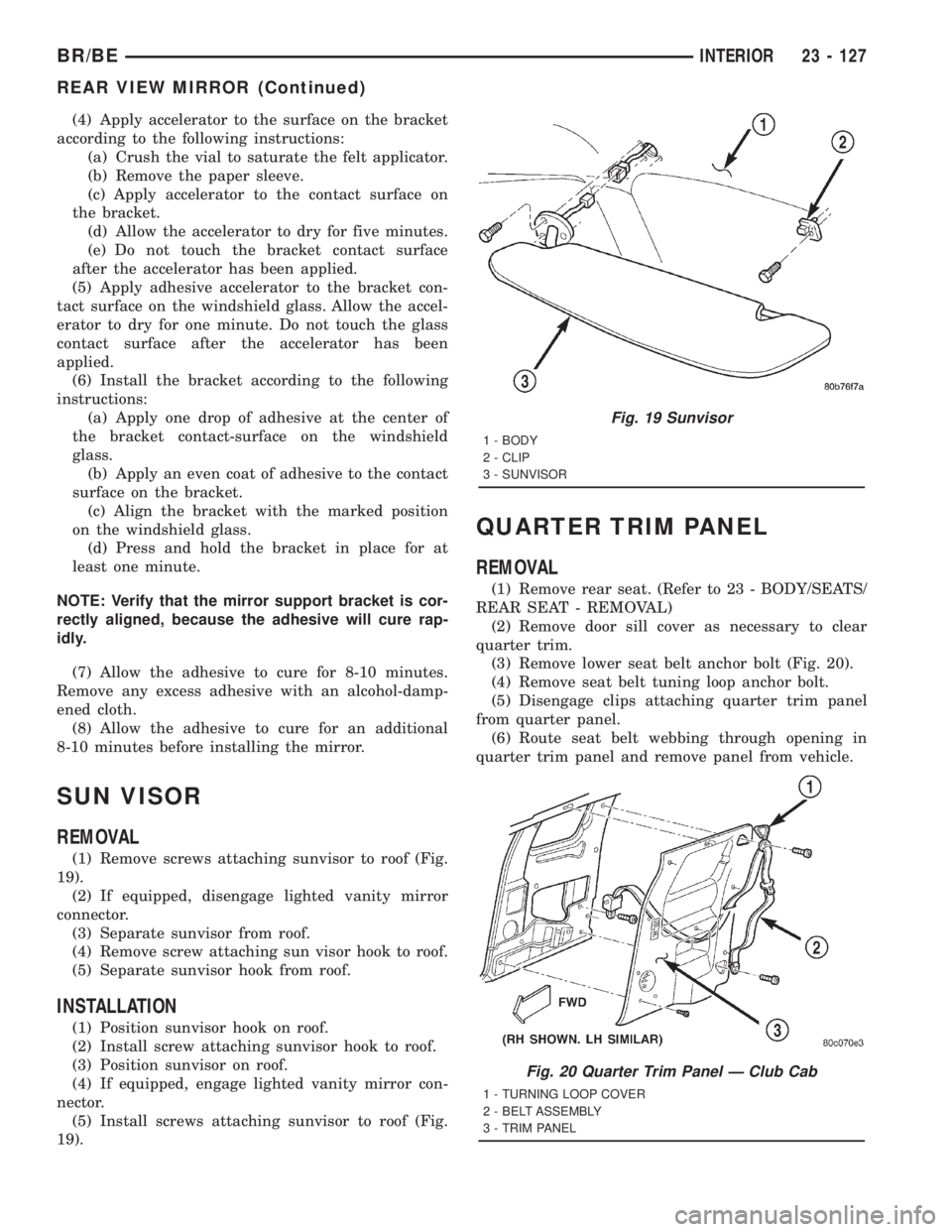
(1) Remove screws attaching sunvisor to roof (Fig.
19).
(2) If equipped, disengage lighted vanity mirror
connector.
(3) Separate sunvisor from roof.
(4) Remove screw attaching sun visor hook to roof.
(5) Separate sunvisor hook from roof.
INSTALLATION
(1) Position sunvisor hook on roof.
(2) Install screw attaching sunvisor hook to roof.
(3) Position sunvisor on roof.
(4) If equipped, engage lighted vanity mirror con-
nector.
(5) Install screws attaching sunvisor to roof (Fig.
19).
QUARTER TRIM PANEL
REMOVAL
(1) Remove rear seat. (Refer to 23 - BODY/SEATS/
REAR SEAT - REMOVAL)
(2) Remove door sill cover as necessary to clear
quarter trim.
(3) Remove lower seat belt anchor bolt (Fig. 20).
(4) Remove seat belt tuning loop anchor bolt.
(5) Disengage clips attaching quarter trim panel
from quarter panel.
(6) Route seat belt webbing through opening in
quarter trim panel and remove panel from vehicle.
Fig. 19 Sunvisor
1 - BODY
2 - CLIP
3 - SUNVISOR
Fig. 20 Quarter Trim Panel Ð Club Cab
1 - TURNING LOOP COVER
2 - BELT ASSEMBLY
3 - TRIM PANEL
BR/BEINTERIOR 23 - 127
REAR VIEW MIRROR (Continued)
Page 2723 of 2889
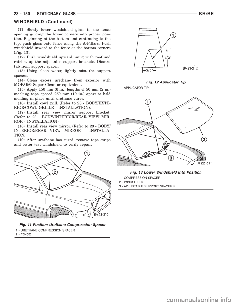
(11) Slowly lower windshield glass to the fence
opening guiding the lower corners into proper posi-
tion. Beginning at the bottom and continuing to the
top, push glass onto fence along the A-Pillars. Push
windshield inward to the fence at the bottom corners
(Fig. 13).
(12) Push windshield upward, snug with roof and
ratchet up the adjustable support brackets. Discard
tab from support spacer.
(13) Using clean water, lightly mist the support
spacers.
(14) Clean excess urethane from exterior with
MOPARž Super Clean or equivalent.
(15) Apply 150 mm (6 in.) lengths of 50 mm (2 in.)
masking tape spaced 250 mm (10 in.) apart to hold
molding in place until urethane cures.
(16) Install cowl grill. (Refer to 23 - BODY/EXTE-
RIOR/COWL GRILLE - INSTALLATION).
(17) Install rear view mirror support bracket.
(Refer to 23 - BODY/INTERIOR/REAR VIEW MIR-
ROR - INSTALLATION).
(18) Install rear view mirror. (Refer to 23 - BODY/
INTERIOR/REAR VIEW MIRROR - INSTALLA-
TION).
(19) After urethane has cured, remove tape strips
and water test windshield to verify repair.
Fig. 11 Position Urethane Compression Spacer
1 - URETHANE COMPRESSION SPACER
2 - FENCE
Fig. 12 Applicator Tip
1 - APPLICATOR TIP
Fig. 13 Lower Windshield Into Position
1 - COMPRESSION SPACER
2 - WINDSHIELD
3 - ADJUSTABLE SUPPORT SPACERS
23 - 150 STATIONARY GLASSBR/BE
WINDSHIELD (Continued)
Page 2869 of 2889
MANIFOLD - INSTALLATION, INTAKE.....9-111,
9-166,9-223,9-302,9-53
MANIFOLD - OPERATION, EXHAUST.....9-112,
9-168,9-224,9-55
MANIFOLD - OPERATION, FUEL DRAIN . . . 14-86
MANIFOLD - OPERATION, INTAKE . . 9-109,9-165,
9-52
MANIFOLD - REMOVAL, EXHAUST . . 9-112,9-168,
9-225,9-303,9-55
MANIFOLD - REMOVAL, FUEL DRAIN.....14-86
MANIFOLD - REMOVAL, INTAKE . . . 9-110,9-166,
9-222,9-301,9-53
MANIFOLD LEAKAGE - DIAGNOSIS AND
TESTING, INTAKE......9-110,9-165,9-222,9-53
MANUAL BLEEDING - STANDARD
PROCEDURE..........................5-7
MANUAL, NV3500....................21-41
MANUAL, NV4500....................21-83
MANUAL TRANSMISSION - DIAGNOSIS
AND TESTING..............21-3,21-46,21-93
MANUAL TRANSMISSION -
INSTALLATION, SHIFT BOOT...........23-122
MANUAL TRANSMISSION - REMOVAL,
SHIFT BOOT........................23-122
MANUAL TRANSMISSION, SPECIAL
TOOLS - NV5600....................21-127
MAP SENSOR - INSTALLATION.........14-104
MARKER LAMP - INSTALLATION........8L-23
MARKER LAMP - REMOVAL............8L-22
MASTER CYLINDER - DESCRIPTION......5-29
MASTER CYLINDER - INSTALLATION.......5-30
MASTER CYLINDER - OPERATION........5-29
MASTER CYLINDER - REMOVAL..........5-30
MASTER CYLINDER BLEEDING -
STANDARD PROCEDURE................5-30
MASTER CYLINDER/POWER BOOSTER -
DIAGNOSIS AND TESTING..............5-29
MATCH MOUNTING - STANDARD
PROCEDURES........................22-2
MATS - INSTALLATION, CARPETS AND
FLOOR............................23-123
MATS - REMOVAL, CARPETS AND
FLOOR............................23-123
MEASUREMENT - STANDARD
PROCEDURES, CASTER CORRECTION......2-3
MEASUREMENTS, SPECIFICATIONS -
BODY GAP AND FLUSH................23-56
MEASURING TIMING CHAIN STRETCH -
INSPECTION..........9-114,9-170,9-227,9-58
MECHANICAL - DIAGNOSIS AND
TESTING...............9-120,9-175,9-6,9-63
MECHANICAL - DIAGNOSIS AND
TESTING, ENGINE DIAGNOSIS..........9-232
MECHANISM - ADJUSTMENT, SHIFT....21-252,
21-423,21-596,21-769
MECHANISM - DESCRIPTION, SHIFT....21-251,
21-422,21-595,21-768
MECHANISM - INSTALLATION, SHIFT.....21-89
MECHANISM - OPERATION, SHIFT......21-251,
21-422,21-595,21-768
MECHANISM - REMOVAL, SHIFT........21-88
MEDIUM DUTY TRUCK MAINTENANCE
SCHEDULE (8.0L 2500 & 3500
MODELS - CALIFORNIA ONLY) -
DESCRIPTION........................0-13
METRIC SYSTEM - DESCRIPTION......Intro.-6
MILE, SPECIFICATIONS - TIRE
REVOLUTIONS PER....................22-9
MINI-TRIP COMPUTER - DIAGNOSIS &
TESTING, COMPASS..................8M-10
MIRROR - DESCRIPTION, AUTOMATIC
DAY / NIGHT........................8N-10
MIRROR - DESCRIPTION, SIDEVIEW.....8N-13
MIRROR - DIAGNOSIS AND TESTING,
AUTOMATIC DAY/NIGHT...............8N-11
MIRROR - DIAGNOSIS AND TESTING,
SIDEVIEW..........................8N-13
MIRROR - INSPECTION................30-19
MIRROR - INSTALLATION, AUTOMATIC
DAY / NIGHT........................8N-12
MIRROR - INSTALLATION, REAR VIEW
. . 23-126
MIRROR - INSTALLATION, SIDE VIEW
....23-97
MIRROR - LOW MOUNTED -
INSTALLATION, SIDE VIEW
.............23-98
MIRROR - LOW MOUNTED - REMOVAL,
SIDE VIEW
..........................23-98
MIRROR - OPERATION, AUTOMATIC DAY
/ NIGHT
............................8N-11MIRROR - OPERATION, SIDEVIEW.......8N-13
MIRROR - REMOVAL, AUTOMATIC DAY /
NIGHT.............................8N-12
MIRROR - REMOVAL, REAR VIEW......23-126
MIRROR - REMOVAL, SIDE VIEW........23-97
MIRROR - REMOVAL, SIDEVIEW........8N-14
MIRROR FLAG - INSTALLATION, SIDE
VIEW..............................23-74
MIRROR FLAG - REMOVAL, SIDE VIEW . . . 23-74
MIRROR GLASS - INSTALLATION, SIDE
VIEW..............................23-98
MIRROR GLASS - REMOVAL, SIDE VIEW . . 23-98
MIRROR GRID - DESCRIPTION, HEATED . . . 8G-4
MIRROR GRID - DIAGNOSIS AND
TESTING, HEATED.....................8G-4
MIRROR GRID - OPERATION, HEATED.....8G-4
MIRROR SUPPORT BRACKET -
INSTALLATION, REARVIEW............23-126
MIRROR SWITCH - DESCRIPTION........8G-3
MIRROR SWITCH - DESCRIPTION,
POWER............................8N-12
MIRROR SWITCH - DIAGNOSIS AND
TESTING, HEATED.....................8G-3
MIRROR SWITCH - INSTALLATION,
POWER............................8N-13
MIRROR SWITCH - OPERATION..........8G-3
MIRROR SWITCH - OPERATION, POWER . . 8N-12
MIRROR SWITCH - REMOVAL, POWER . . . 8N-12
MIRROR SYSTEM - DESCRIPTION,
HEATED..............................8G-1
MIRROR SYSTEM - DIAGNOSIS AND
TESTING, HEATED.....................8G-2
MIRROR SYSTEM - OPERATION, HEATED . . 8G-2
MIRRORS - DESCRIPTION, POWER......8N-10
MIRRORS - OPERATION, POWER........8N-10
MODE - DESCRIPTION, CIRCUIT
ACTUATION TEST.....................25-1
MODE - DESCRIPTION, STATE DISPLAY
TEST...............................25-1
MODES OF OPERATION - DESCRIPTION . . . 8E-14
MODULE - DESCRIPTION, AIRBAG
CONTROL...........................8O-6
MODULE - DESCRIPTION, BODY
CONTROL/CENTRAL TIMER..............8E-1
MODULE - DESCRIPTION, DAYTIME
RUNNING LAMP......................8L-9
MODULE - DESCRIPTION, FUEL PUMP....14-12
MODULE - DESCRIPTION, FUEL TANK....14-78
MODULE - DESCRIPTION, WIPER.......8R-14
MODULE - DIAGNOSIS AND TESTING,
CENTRAL TIMER......................8E-4
MODULE - INSTALLATION, AIRBAG
CONTROL...........................8O-8
MODULE - INSTALLATION, BODY
CONTROL/CENTRAL TIMER..............8E-6
MODULE - INSTALLATION, DAYTIME
RUNNING LAMP......................8L-9
MODULE - INSTALLATION, ENGINE
CONTROL..........................8E-14
MODULE - INSTALLATION, FUEL PUMP . . . 14-13
MODULE - INSTALLATION, FUEL TANK....14-79
MODULE - INSTALLATION, POWERTRAIN
CONTROL..........................8E-20
MODULE - INSTALLATION, WIPER.......8R-15
MODULE - OPERATION, AIRBAG
CONTROL...........................8O-6
MODULE - OPERATION, BODY
CONTROL/CENTRAL TIMER..............8E-3
MODULE - OPERATION, DAYTIME
RUNNING LAMP......................8L-9
MODULE - OPERATION, FUEL PUMP.....14-13
MODULE - OPERATION, FUEL TANK......14-78
MODULE - OPERATION, WIPER.........8R-14
MODULE - REMOVAL, AIRBAG CONTROL . . 8O-7
MODULE - REMOVAL, BODY CONTROL/
CENTRAL TIMER......................8E-5
MODULE - REMOVAL, DAYTIME
RUNNING LAMP......................8L-9
MODULE - REMOVAL, ENGINE CONTROL . . 8E-14
MODULE - REMOVAL, FUEL PUMP.......14-13
MODULE - REMOVAL, FUEL TANK.......14-78
MODULE - REMOVAL, POWERTRAIN
CONTROL..........................8E-19
MODULE - REMOVAL, WIPER
...........8R-14
MOLDING - INSTALLATION, ROOF JOINT
. . 23-91
MOLDING - REMOVAL, ROOF JOINT
......23-91
MOLDINGS - INSTALLATION, BODY SIDE
. . 23-87
MOLDINGS - REMOVAL, BODY SIDE
.....23-87MOLEX - INSTALLATION, CONNECTOR . 8W-01-9
MOLEX - REMOVAL, CONNECTOR.....8W-01-9
MONITORED SYSTEMS - DESCRIPTION . . . 25-15
MONITORS - DIESEL ENGINES -
DESCRIPTION, COMPONENT............25-18
MONITORS - GAS ENGINES -
DESCRIPTION, COMPONENT............25-18
MOTOR - ASSEMBLY, AXLE VACUUM . . 3-33,3-65
MOTOR - DESCRIPTION, AXLE VACUUM . . . 3-29,
3-62
MOTOR - DESCRIPTION, BLOWER.......24-32
MOTOR - DESCRIPTION, ENGINE
STARTER ...........................8F-39
MOTOR - DESCRIPTION, IDLE AIR
CONTROL..........................14-41
MOTOR - DESCRIPTION, LUMBAR.......8N-18
MOTOR - DESCRIPTION, POWER LOCK....8N-6
MOTOR - DESCRIPTION, RECLINER......8N-20
MOTOR - DESCRIPTION, WINDOW......8N-26
MOTOR - DIAGNOSIS AND TESTING,
BLOWER...........................24-33
MOTOR - DIAGNOSIS AND TESTING,
POWER LOCK........................8N-7
MOTOR - DIAGNOSIS AND TESTING,
STARTER ...........................8F-39
MOTOR - DIAGNOSIS AND TESTING,
VACUUM........................3-31,3-63
MOTOR - DIAGNOSIS AND TESTING,
WINDOW...........................8N-26
MOTOR - DISASSEMBLY, AXLE VACUUM . . 3-33,
3-65
MOTOR - INSTALLATION, AXLE VACUUM . . 3-33,
3-65
MOTOR - INSTALLATION, BLOWER......24-33
MOTOR - INSTALLATION, ENGINE
STARTER ...........................8F-41
MOTOR - OPERATION, AXLE VACUUM . 3-30,3-62
MOTOR - OPERATION, BLOWER.........24-32
MOTOR - OPERATION, ENGINE STARTER . . 8F-39
MOTOR - OPERATION, IDLE AIR
CONTROL..........................14-41
MOTOR - OPERATION, LUMBAR........8N-18
MOTOR - OPERATION, POWER LOCK.....8N-6
MOTOR - OPERATION, RECLINER.......8N-21
MOTOR - REMOVAL, AXLE VACUUM . . 3-33,3-65
MOTOR - REMOVAL, BLOWER..........24-33
MOTOR - REMOVAL, ENGINE STARTER . . . 8F-40
MOTOR - REMOVAL, WINDOW..........8N-26
MOTOR RELAY - DESCRIPTION,
BLOWER...........................24-22
MOTOR RELAY - DESCRIPTION, ENGINE
STARTER ...........................8F-42
MOTOR RELAY - DIAGNOSIS AND
TESTING, BLOWER...................24-22
MOTOR RELAY - INSTALLATION,
BLOWER...........................24-23
MOTOR RELAY - INSTALLATION, ENGINE
STARTER ...........................8F-43
MOTOR RELAY - OPERATION, BLOWER . . . 24-22
MOTOR RELAY - OPERATION, ENGINE
STARTER ...........................8F-42
MOTOR RELAY - REMOVAL, BLOWER....24-23
MOTOR RELAY - REMOVAL, ENGINE
STARTER ...........................8F-43
MOTOR RESISTOR BLOCK -
DESCRIPTION, BLOWER...............24-23
MOTOR RESISTOR BLOCK - DIAGNOSIS
AND TESTING, BLOWER...............24-24
MOTOR RESISTOR BLOCK -
INSTALLATION, BLOWER..............24-24
MOTOR RESISTOR BLOCK - OPERATION,
BLOWER...........................24-23
MOTOR RESISTOR BLOCK - REMOVAL,
BLOWER...........................24-24
MOTOR SWITCH - DESCRIPTION,
BLOWER...........................24-24
MOTOR SWITCH - DIAGNOSIS AND
TESTING, BLOWER...................24-25
MOTOR SWITCH - OPERATION, BLOWER . . 24-25
MOTOR SWITCH - REMOVAL, BLOWER
. . . 24-25
MOUNT - INSTALLATION, FRONT
. . . 9-100,9-156,
9-213,9-290,9-43
MOUNT - INSTALLATION, REAR
....9-101,9-158,
9-213,9-291,9-44
MOUNT - REMOVAL, FRONT
. 9-100,9-156,9-213,
9-290,9-43
MOUNT - REMOVAL, REAR
. . 9-101,9-157,9-213,
9-291,9-44
22 INDEXBR/BE
Description Group-Page Description Group-Page Description Group-Page