air suspension DODGE RAM 2001 Service Repair Manual
[x] Cancel search | Manufacturer: DODGE, Model Year: 2001, Model line: RAM, Model: DODGE RAM 2001Pages: 2889, PDF Size: 68.07 MB
Page 1 of 2889
GROUP TAB LOCATOR
Introduction
0Lubrication & Maintenance
2Suspension
3Differential & Driveline
5Brakes
7Cooling
8AAudio
8BChime/Buzzer
8EElectronic Control Modules
8FEngine Systems
8GHeated Systems
8HHorn
8IIgnition Control
8JInstrument Cluster
8LLamps
8MMessage Systems
8NPower Systems
8ORestraints
8PSpeed Control
8QVehicle Theft Security
8RWipers/Washers
8WWiring
9Engine
11Exhaust System
13Frame & Bumpers
14Fuel System
19Steering
21Transmission/Transaxle
22Tires/Wheels
23Body
24Heating & Air Conditioning
25Emissions Control Systems
30New Vehicle Preparation
Component and System Index
Service Manual Comment Forms (Rear of Manual)
Page 45 of 2889
OPERATION
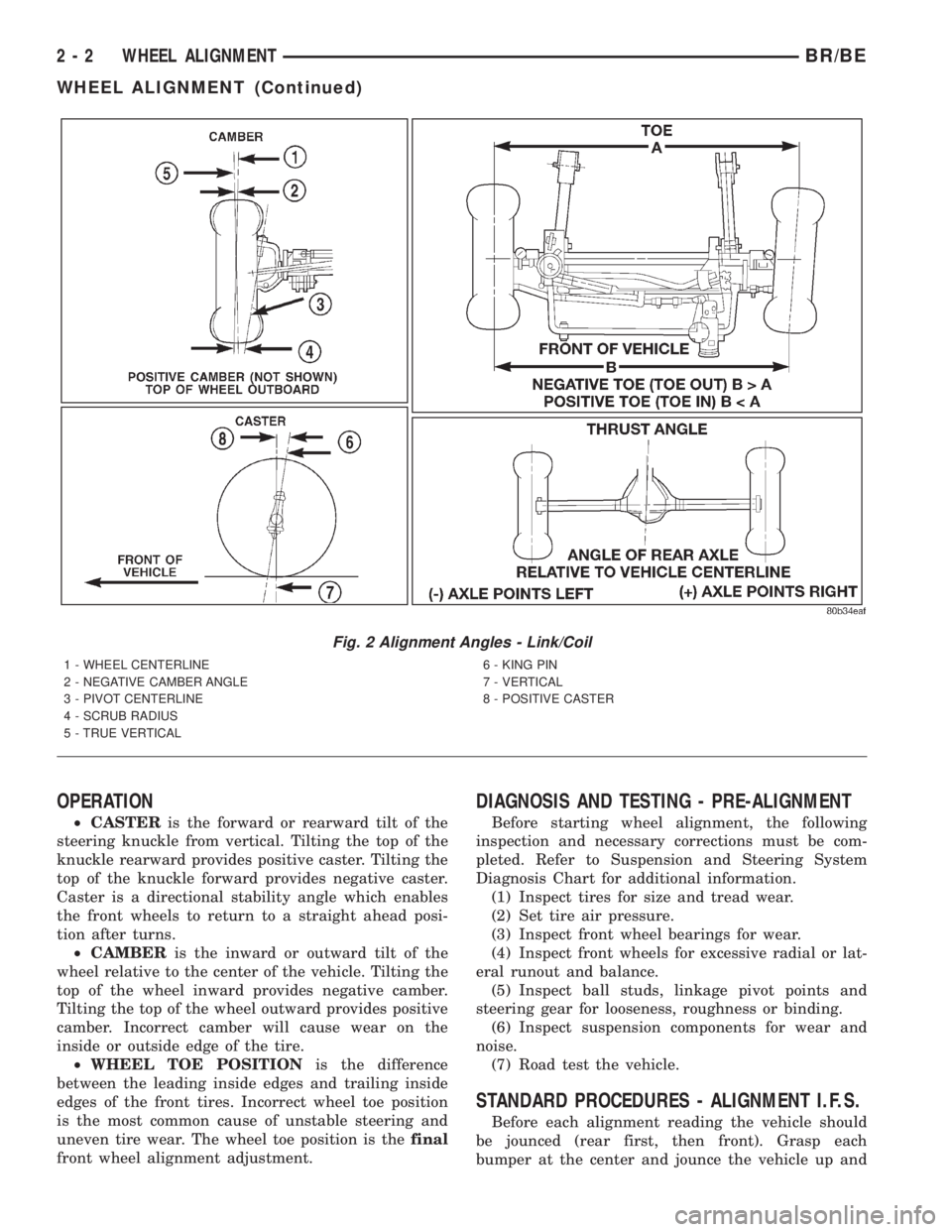
²CASTERis the forward or rearward tilt of the
steering knuckle from vertical. Tilting the top of the
knuckle rearward provides positive caster. Tilting the
top of the knuckle forward provides negative caster.
Caster is a directional stability angle which enables
the front wheels to return to a straight ahead posi-
tion after turns.
²CAMBERis the inward or outward tilt of the
wheel relative to the center of the vehicle. Tilting the
top of the wheel inward provides negative camber.
Tilting the top of the wheel outward provides positive
camber. Incorrect camber will cause wear on the
inside or outside edge of the tire.
²WHEEL TOE POSITIONis the difference
between the leading inside edges and trailing inside
edges of the front tires. Incorrect wheel toe position
is the most common cause of unstable steering and
uneven tire wear. The wheel toe position is thefinal
front wheel alignment adjustment.
DIAGNOSIS AND TESTING - PRE-ALIGNMENT
Before starting wheel alignment, the following
inspection and necessary corrections must be com-
pleted. Refer to Suspension and Steering System
Diagnosis Chart for additional information.
(1) Inspect tires for size and tread wear.
(2) Set tire air pressure.
(3) Inspect front wheel bearings for wear.
(4) Inspect front wheels for excessive radial or lat-
eral runout and balance.
(5) Inspect ball studs, linkage pivot points and
steering gear for looseness, roughness or binding.
(6) Inspect suspension components for wear and
noise.
(7) Road test the vehicle.
STANDARD PROCEDURES - ALIGNMENT I.F.S.
Before each alignment reading the vehicle should
be jounced (rear first, then front). Grasp each
bumper at the center and jounce the vehicle up and
Fig. 2 Alignment Angles - Link/Coil
1 - WHEEL CENTERLINE
2 - NEGATIVE CAMBER ANGLE
3 - PIVOT CENTERLINE
4 - SCRUB RADIUS
5 - TRUE VERTICAL6 - KING PIN
7 - VERTICAL
8 - POSITIVE CASTER
2 - 2 WHEEL ALIGNMENTBR/BE
WHEEL ALIGNMENT (Continued)
Page 54 of 2889
(5) Install the steering knuckle on the lower ball
joint. Install the lower ball joint nut and tighten to:
²LD: 129 N´m (95 ft. lbs.)
²HD: 136 N´m (110 ft. lbs.)
(5) Install the lower ball joint cotter pin.
(6) Install the stabilizer bar link on the lower sus-
pension arm. Install the grommet, retainer and nut
and tighten to 37 N´m (27 ft. lbs.).
(7) Install the tie rod end on the steering knuckle
and tighten nut to 108 N´m (80 ft. lbs.). Install cotter
pin.
(8) Install the brake rotor and caliper assembly,
(Refer to 5 - BRAKES/HYDRAULIC/MECHANICAL/
ROTORS - INSTALLATION).
(9) Install the tire and wheel assembly, (Refer to
22 - TIRES/WHEELS/WHEELS - STANDARD PRO-
CEDURE).
(10) Remove the support and lower the vehicle.
(11) Tighten the suspension arm crossmember
nuts to 169 N´m (125 ft. lbs.).
SHOCK
DESCRIPTION
The top of the shocks mounts on frame brackets
using grommets. The bottom of the shock is bolted to
the lower suspension arms.
OPERATION
The shock absorbers dampen jounce and rebound
of the vehicle over various road conditions.
DIAGNOSIS AND TESTING - SHOCK
A knocking or rattling noise from a shock absorber
may be caused by movement between mounting
bushings and metal brackets or attaching compo-
nents. These noises can usually be stopped by tight-
ening the attaching nuts. If the noise persists,
inspect for damaged and worn bushings, and attach-
ing components. Repair as necessary if any of these
conditions exist.
A squeaking noise from the shock absorber may be
caused by the hydraulic valving and may be intermit-
tent. This condition is not repairable and the shock
absorber must be replaced.
The shock absorbers are not refillable or adjust-
able. If a malfunction occurs, the shock absorber
must be replaced. To test a shock absorber, hold it in
an upright position and force the piston in and out of
the cylinder four or five times. The action throughout
each stroke should be smooth and even.
The shock absorber bushings do not require any
type of lubrication. Do not attempt to stop bushing
noise by lubricating them. Grease and mineral oil-
base lubricants will deteriorate the bushing.
REMOVAL
(1) Raise and support vehicle.
(2) Remove shock upper nut and remove retainer
and grommet.
(3) Remove lower mounting bolt from suspension
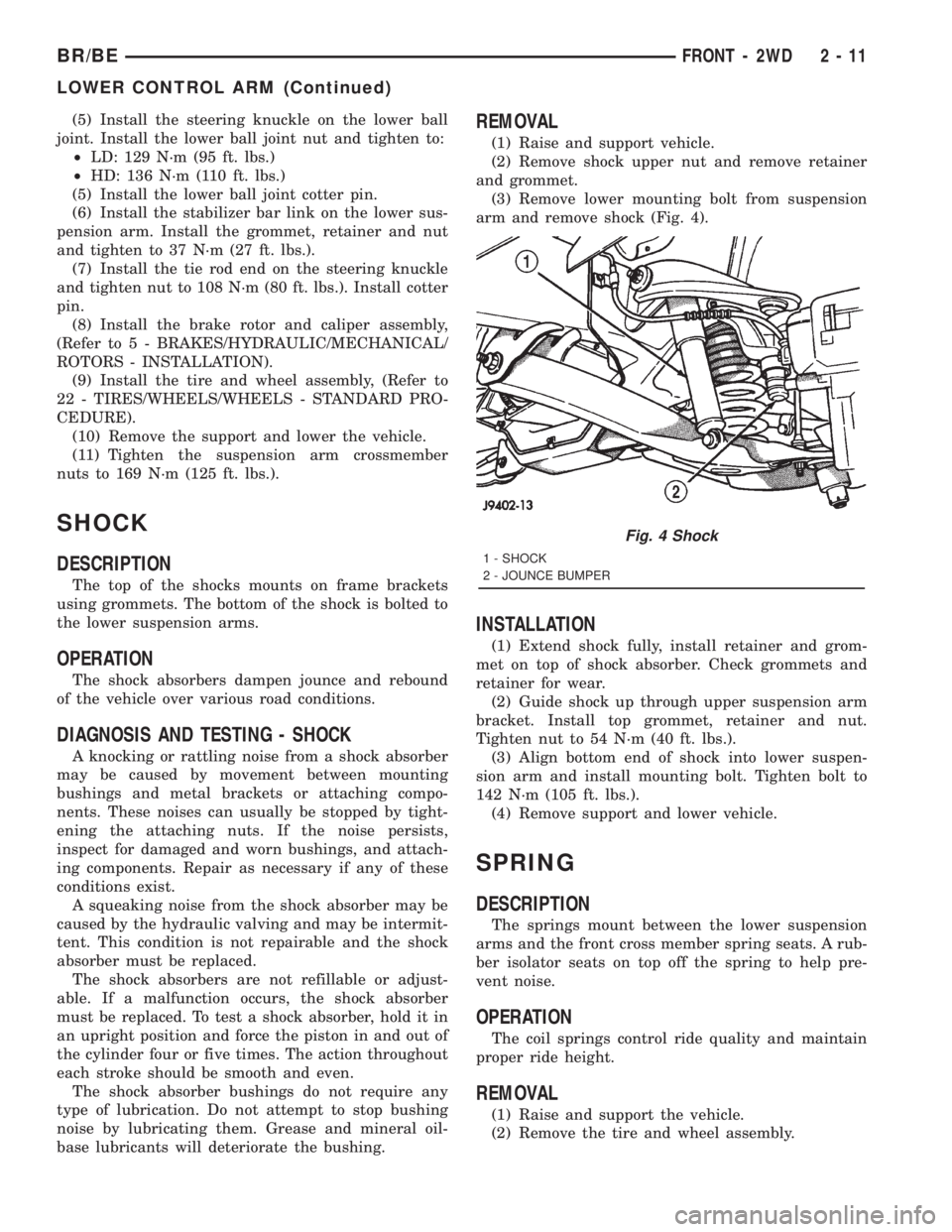
arm and remove shock (Fig. 4).
INSTALLATION
(1) Extend shock fully, install retainer and grom-
met on top of shock absorber. Check grommets and
retainer for wear.
(2) Guide shock up through upper suspension arm
bracket. Install top grommet, retainer and nut.
Tighten nut to 54 N´m (40 ft. lbs.).
(3) Align bottom end of shock into lower suspen-
sion arm and install mounting bolt. Tighten bolt to
142 N´m (105 ft. lbs.).
(4) Remove support and lower vehicle.
SPRING
DESCRIPTION
The springs mount between the lower suspension
arms and the front cross member spring seats. A rub-
ber isolator seats on top off the spring to help pre-
vent noise.
OPERATION
The coil springs control ride quality and maintain
proper ride height.
REMOVAL
(1) Raise and support the vehicle.
(2) Remove the tire and wheel assembly.
Fig. 4 Shock
1 - SHOCK
2 - JOUNCE BUMPER
BR/BEFRONT - 2WD 2 - 11
LOWER CONTROL ARM (Continued)
Page 64 of 2889
SHOCK
DESCRIPTION
The shocks are mounted inside the springs and
attached at the top to brackets with grommets. These
brackets are bolted on the frame with three studs on
a ring. The shock is mounted at the bottom of the
axle below the spring seat.
OPERATION
The shock absorbers dampen the jounce and
rebound of the vehicle over various road conditions.
DIAGNOSIS AND TESTING - SHOCK
A knocking or rattling noise from a shock absorber
may be caused by movement between mounting
bushings and metal brackets or attaching compo-
nents. These noises can usually be stopped by tight-
ening the attaching nuts. If the noise persists,
inspect for damaged and worn bushings, and attach-
ing components. Repair as necessary if any of these
conditions exist.
A squeaking noise from the shock absorber may be
caused by the hydraulic valving and may be intermit-
tent. This condition is not repairable and the shock
absorber must be replaced.
The shock absorbers are not refillable or adjust-
able. If a malfunction occurs, the shock absorbermust be replaced. To test a shock absorber, hold it in
an upright position and force the piston in and out of
the cylinder four or five times. The action throughout
each stroke should be smooth and even.
The shock absorber bushings do not require any
type of lubrication. Do not attempt to stop bushing
noise by lubricating them. Grease and mineral oil-
base lubricants will deteriorate the bushing.
REMOVAL
(1) Remove the nut, retainer and grommet from
the upper stud in the engine compartment.
(2) Remove three nuts from the upper shock
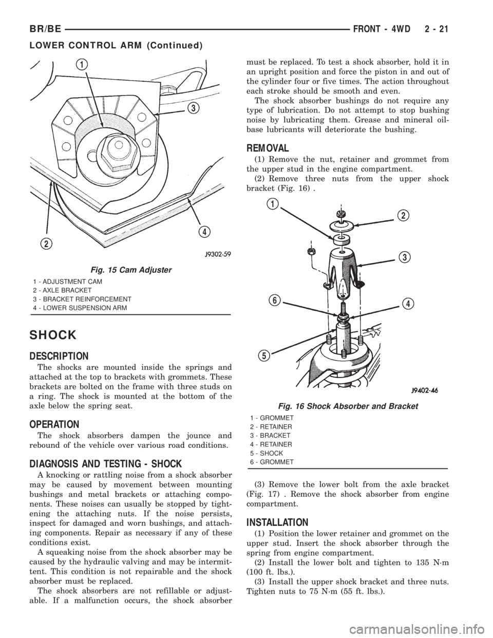
bracket (Fig. 16) .
(3) Remove the lower bolt from the axle bracket
(Fig. 17) . Remove the shock absorber from engine
compartment.
INSTALLATION
(1) Position the lower retainer and grommet on the
upper stud. Insert the shock absorber through the
spring from engine compartment.
(2) Install the lower bolt and tighten to 135 N´m
(100 ft. lbs.).
(3) Install the upper shock bracket and three nuts.
Tighten nuts to 75 N´m (55 ft. lbs.).
Fig. 15 Cam Adjuster
1 - ADJUSTMENT CAM
2 - AXLE BRACKET
3 - BRACKET REINFORCEMENT
4 - LOWER SUSPENSION ARM
Fig. 16 Shock Absorber and Bracket
1 - GROMMET
2 - RETAINER
3 - BRACKET
4 - RETAINER
5 - SHOCK
6 - GROMMET
BR/BEFRONT - 4WD 2 - 21
LOWER CONTROL ARM (Continued)
Page 69 of 2889
REAR
TABLE OF CONTENTS
page page
REAR
DESCRIPTION...........................26
DIAGNOSIS AND TESTING.................26
SPRING AND SHOCK....................26
SPECIFICATIONS........................27
SPECIAL TOOLS.........................28
BUSHINGS
REMOVAL..............................28
INSTALLATION...........................28
JOUNCE BUMPER
DESCRIPTION...........................28
OPERATION.............................28
SHOCK
DESCRIPTION...........................28OPERATION.............................28
REMOVAL..............................28
INSTALLATION...........................28
SPRING
DESCRIPTION...........................28
OPERATION.............................28
REMOVAL..............................28
INSTALLATION...........................29
STABILIZER BAR
DESCRIPTION...........................30
OPERATION.............................30
REMOVAL..............................30
INSTALLATION...........................30
REAR
DESCRIPTION
The rear suspension is comprised of:
²Shock Absorbers
²Jounce Bumpers
²Stabilizer Bar (optional)
²Leaf Springs
²Drive Axle
CAUTION: A vehicle should always be loaded so
the vehicle weight center-line is located immedi-
ately forward of the rear axle. Correct vehicle load-
ing provides proper front tire-to-road contact. This
results in maximum vehicle handling stability and
safety. Incorrect vehicle weight distribution can
cause excessive tire tread wear, spring fatigue or
failure, and erratic steering.
CAUTION: Suspension components with rubber/ure-
thane bushings (except stabilizer bar) should be
tightened with the vehicle at normal ride height. It is
important to have the springs supporting the weight
of the vehicle when the fasteners are torqued. If
springs are not at their normal ride position, vehicle
ride comfort could be affected and premature bush-
ing wear may occur.
DIAGNOSIS AND TESTING - SPRING AND
SHOCK
A knocking or rattling noise from a shock absorber
may be caused by movement between mounting
bushings and metal brackets or attaching compo-
nents. These noises can usually be stopped by tight-
ening the attaching nuts. If the noise persists,
inspect for damaged and worn bushings, and attach-
ing components. Repair as necessary if any of these
conditions exist.
A squeaking noise from the shock absorber may be
caused by the hydraulic valving and may be intermit-
tent. This condition is not repairable and the shock
absorber must be replaced.
The shock absorbers are not refillable or adjust-
able. If a malfunction occurs, the shock absorber
must be replaced. To test a shock absorber, hold it in
an upright position and force the piston in and out of
the cylinder four or five times. The action throughout
each stroke should be smooth and even.
The spring eye and shock absorber bushings do not
require any type of lubrication. Do not attempt to
stop spring bushing noise by lubricating them.
Grease and mineral oil-base lubricants will deterio-
rate the bushing rubber.
If the vehicle is used for severe, off-road operation,
the springs should be examined periodically. Check
for broken and shifted leafs, loose and missing clips,
and broken center bolts. Refer to Spring and Shock
Absorber Diagnosis chart for additional information.
2 - 26 REARBR/BE
Page 276 of 2889
WARNING
WARNING: DUST AND DIRT ACCUMULATING ON
BRAKE PARTS DURING NORMAL USE MAY CON-
TAIN ASBESTOS FIBERS FROM PRODUCTION OR
AFTERMARKET LININGS. BREATHING EXCESSIVE
CONCENTRATIONS OF ASBESTOS FIBERS CAN
CAUSE SERIOUS BODILY HARM. EXERCISE CARE
WHEN SERVICING BRAKE PARTS. DO NOT CLEAN
BRAKE PARTS WITH COMPRESSED AIR OR BY
DRY BRUSHING. USE A VACUUM CLEANER SPE-
CIFICALLY DESIGNED FOR THE REMOVAL OF
ASBESTOS FIBERS FROM BRAKE COMPONENTS.
IF A SUITABLE VACUUM CLEANER IS NOT AVAIL-
ABLE, CLEANING SHOULD BE DONE WITH A
WATER DAMPENED CLOTH. DO NOT SAND, OR
GRIND BRAKE LINING UNLESS EQUIPMENT USED
IS DESIGNED TO CONTAIN THE DUST RESIDUE.
DISPOSE OF ALL RESIDUE CONTAINING ASBES-
TOS FIBERS IN SEALED BAGS OR CONTAINERS
TO MINIMIZE EXPOSURE TO YOURSELF AND OTH-
ERS. FOLLOW PRACTICES PRESCRIBED BY THE
OCCUPATIONAL SAFETY AND HEALTH ADMINIS-
TRATION AND THE ENVIRONMENTAL PROTECTION
AGENCY FOR THE HANDLING, PROCESSING, AND
DISPOSITION OF DUST OR DEBRIS THAT MAY
CONTAIN ASBESTOS FIBERS.
CAUTION: Never use gasoline, kerosene, alcohol,
motor oil, transmission fluid, or any fluid containing
mineral oil to clean the system components. These
fluids damage rubber cups and seals. Use only
fresh brake fluid or Mopar brake cleaner to clean or
flush brake system components. These are the only
cleaning materials recommended. If system contam-
ination is suspected, check the fluid for dirt, discol-
oration, or separation into distinct layers. Also
check the reservoir cap seal for distortion. Drain
and flush the system with new brake fluid if con-
tamination is suspected.
CAUTION: Use Mopar brake fluid, or an equivalent
quality fluid meeting SAE/DOT standards J1703 and
DOT 3. Brake fluid must be clean and free of con-
taminants. Use fresh fluid from sealed containers
only to ensure proper antilock component opera-
tion.
CAUTION: Use Mopar multi-mileage or high temper-
ature grease to lubricate caliper slide surfaces,
drum brake pivot pins, and shoe contact points on
the backing plates. Use multi-mileage grease or GE
661 or Dow 111 silicone grease on caliper slide pins
to ensure proper operation.
DIAGNOSIS AND TESTING - BASE BRAKE
SYSTEM
Base brake components consist of the brake shoes,
calipers, wheel cylinders, brake drums, rotors, brake
lines, master cylinder, booster, and parking brake
components.
Brake diagnosis involves determining if the prob-
lem is related to a mechanical, hydraulic, or vacuum
operated component.
The first diagnosis step is the preliminary check.
PRELIMINARY BRAKE CHECK
(1) Check condition of tires and wheels. Damaged
wheels and worn, damaged, or underinflated tires
can cause pull, shudder, vibration, and a condition
similar to grab.
(2) If complaint was based on noise when braking,
check suspension components. Jounce front and rear
of vehicle and listen for noise that might be caused
by loose, worn or damaged suspension or steering
components.
(3) Inspect brake fluid level and condition. Note
that the brake reservoir fluid level will decrease in
proportion to normal lining wear.Also note that
brake fluid tends to darken over time. This is
normal and should not be mistaken for contam-
ination.
(a) If fluid level is abnormally low, look for evi-
dence of leaks at calipers, wheel cylinders, brake
lines, and master cylinder.
(b) If fluid appears contaminated, drain out a
sample to examine. System will have to be flushed
if fluid is separated into layers, or contains a sub-
stance other than brake fluid. The system seals
and cups will also have to be replaced after flush-
ing. Use clean brake fluid to flush the system.
(4) Check parking brake operation. Verify free
movement and full release of cables and pedal. Also
note if vehicle was being operated with parking
brake partially applied.
(5) Check brake pedal operation. Verify that pedal
does not bind and has adequate free play. If pedal
lacks free play, check pedal and power booster for
being loose or for bind condition. Do not road test
until condition is corrected.
(6) Check booster vacuum check valve and hose.
(7) If components checked appear OK, road test
the vehicle.
ROAD TESTING
(1) If complaint involved low brake pedal, pump
pedal and note if it comes back up to normal height.
(2) Check brake pedal response with transmission
in Neutral and engine running. Pedal should remain
firm under constant foot pressure.
BR/BEBRAKES 5 - 5
HYDRAULIC/MECHANICAL (Continued)
Page 277 of 2889
(3) During road test, make normal and firm brake
stops in 25-40 mph range. Note faulty brake opera-
tion such as low pedal, hard pedal, fade, pedal pulsa-
tion, pull, grab, drag, noise, etc.
(4) Attempt to stop the vehicle with the parking
brake only and note grab, drag, noise, etc.
PEDAL FALLS AWAY
A brake pedal that falls away under steady foot
pressure is generally the result of a system leak. The
leak point could be at a brake line, fitting, hose, or
caliper/wheel cylinder. If leakage is severe, fluid will
be evident at or around the leaking component.
Internal leakage (seal by-pass) in the master cylin-
der caused by worn or damaged piston cups, may
also be the problem cause.
An internal leak in the ABS or RWAL system may
also be the problem with no physical evidence.
LOW PEDAL
If a low pedal is experienced, pump the pedal sev-
eral times. If the pedal comes back up, worn linings,
rotors, drums, or rear brakes out of adjustment are
the most likely causes. The proper course of action is
to inspect and replace all worn component and make
the proper adjustments.
SPONGY PEDAL
A spongy pedal is most often caused by air in the
system. However, thin brake drums or substandard
brake lines and hoses can also cause a spongy pedal.
The proper course of action is to bleed the system,
and replace thin drums and substandard quality
brake hoses if suspected.
HARD PEDAL OR HIGH PEDAL EFFORT
A hard pedal or high pedal effort may be due to
lining that is water soaked, contaminated, glazed, or
badly worn. The power booster or check valve could
also be faulty.
PEDAL PULSATION
Pedal pulsation is caused by components that are
loose, or beyond tolerance limits.
The primary cause of pulsation are disc brake
rotors with excessive lateral runout or thickness vari-
ation, or out of round brake drums. Other causes are
loose wheel bearings or calipers and worn or dam-
aged tires.
NOTE: Some pedal pulsation may be felt during
ABS/EBD activation.BRAKE DRAG
Brake drag occurs when the lining is in constant
contact with the rotor or drum. Drag can occur at one
wheel, all wheels, fronts only, or rears only.
Drag is a product of incomplete brake shoe release.
Drag can be minor or severe enough to overheat the
linings, rotors and drums.
Minor drag will usually cause slight surface char-
ring of the lining. It can also generate hard spots in
rotors and drums from the overheat-cool down pro-
cess. In most cases, the rotors, drums, wheels and
tires are quite warm to the touch after the vehicle is
stopped.
Severe drag can char the brake lining all the way
through. It can also distort and score rotors and
drums to the point of replacement. The wheels, tires
and brake components will be extremely hot. In
severe cases, the lining may generate smoke as it
chars from overheating.
Common causes of brake drag are:
²Seized or improperly adjusted parking brake
cables
²Loose/worn wheel bearing
²Seized caliper or wheel cylinder piston
²Caliper binding on damaged or missing anti-rat-
tle clips or bushings
²Loose caliper mounting
²Drum brake shoes binding on worn/damaged
support plates
²Mis-assembled components
²Long booster output rod
If brake drag occurs at all wheels, the problem
may be related to a blocked master cylinder return
port, or faulty power booster (binds-does not release).
BRAKE FADE
Brake fade is usually a product of overheating
caused by brake drag. However, brake overheating
and resulting fade can also be caused by riding the
brake pedal, making repeated high deceleration stops
in a short time span, or constant braking on steep
mountain roads. Refer to the Brake Drag information
in this section for causes.
BRAKE PULL
Front brake pull condition could result from:
²Contaminated lining in one caliper
²Seized caliper piston
²Binding caliper
²Loose caliper
²Damaged anti-rattle clips
²Improper brake shoes
²Damaged rotor
A worn, damaged wheel bearing or suspension
component are further causes of pull. A damaged
5 - 6 BRAKESBR/BE
HYDRAULIC/MECHANICAL (Continued)
Page 278 of 2889
front tire (bruised, ply separation) can also cause
pull.
A common and frequently misdiagnosed pull condi-
tion is where direction of pull changes after a few
stops. The cause is a combination of brake drag fol-
lowed by fade at one of the brake units.
As the dragging brake overheats, efficiency is so
reduced that fade occurs. Since the opposite brake
unit is still functioning normally, its braking effect is
magnified. This causes pull to switch direction in
favor of the normally functioning brake unit.
An additional point when diagnosing a change in
pull condition concerns brake cool down. Remember
that pull will return to the original direction, if the
dragging brake unit is allowed to cool down (and is
not seriously damaged).
REAR BRAKE GRAB OR PULL
Rear grab or pull is usually caused by improperly
adjusted or seized parking brake cables, contami-
nated lining, bent or binding shoes and support
plates, or improperly assembled components. This is
particularly true when only one rear wheel is
involved. However, when both rear wheels are
affected, the master cylinder or proportioning valve
could be at fault.
BRAKES DO NOT HOLD AFTER DRIVING THROUGH DEEP
WATER PUDDLES
This condition is generally caused by water soaked
lining. If the lining is only wet, it can be dried by
driving with the brakes very lightly applied for a
mile or two. However, if the lining is both soaked and
dirt contaminated, cleaning and/or replacement will
be necessary.
BRAKE LINING CONTAMINATION
Brake lining contamination is mostly a product of
leaking calipers or wheel cylinders, worn seals, driv-
ing through deep water puddles, or lining that has
become covered with grease and grit during repair.
Contaminated lining should be replaced to avoid fur-
ther brake problems.
WHEEL AND TIRE PROBLEMS
Some conditions attributed to brake components
may actually be caused by a wheel or tire problem.
A damaged wheel can cause shudder, vibration and
pull. A worn or damaged tire can also cause pull.
Severely worn tires with very little tread left can
produce a grab-like condition as the tire loses and
recovers traction. Flat-spotted tires can cause vibra-
tion and generate shudder during brake operation. A
tire with internal damage such as a severe bruise,
cut, or ply separation can cause pull and vibration.BRAKE NOISES
Some brake noise is common with rear drum
brakes and on some disc brakes during the first few
stops after a vehicle has been parked overnight or
stored. This is primarily due to the formation of trace
corrosion (light rust) on metal surfaces. This light
corrosion is typically cleared from the metal surfaces
after a few brake applications causing the noise to
subside.
BRAKE SQUEAK/SQUEAL
Brake squeak or squeal may be due to linings that
are wet or contaminated with brake fluid, grease, or
oil. Glazed linings and rotors with hard spots can
also contribute to squeak. Dirt and foreign material
embedded in the brake lining will also cause squeak/
squeal.
A very loud squeak or squeal is frequently a sign of
severely worn brake lining. If the lining has worn
through to the brake shoes in spots, metal-to-metal
contact occurs. If the condition is allowed to continue,
rotors and drums can become so scored that replace-
ment is necessary.
BRAKE CHATTER
Brake chatter is usually caused by loose or worn
components, or glazed/burnt lining. Rotors with hard
spots can also contribute to chatter. Additional causes
of chatter are out-of-tolerance rotors, brake lining not
securely attached to the shoes, loose wheel bearings
and contaminated brake lining.
THUMP/CLUNK NOISE
Thumping or clunk noises during braking are fre-
quentlynotcaused by brake components. In many
cases, such noises are caused by loose or damaged
steering, suspension, or engine components. However,
calipers that bind on the slide surfaces can generate
a thump or clunk noise. In addition, worn out,
improperly adjusted, or improperly assembled rear
brake shoes can also produce a thump noise.
STANDARD PROCEDURE - MANUAL BLEEDING
Use Mopar brake fluid, or an equivalent quality
fluid meeting SAE J1703-F and DOT 3 standards
only. Use fresh, clean fluid from a sealed container at
all times.
(1) Remove reservoir filler caps and fill reservoir.
(2) If calipers, or wheel cylinders were overhauled,
open all caliper and wheel cylinder bleed screws.
Then close each bleed screw as fluid starts to drip
from it. Top off master cylinder reservoir once more
before proceeding.
(3) Attach one end of bleed hose to bleed screw
and insert opposite end in glass container partially
BR/BEBRAKES 5 - 7
HYDRAULIC/MECHANICAL (Continued)
Page 533 of 2889
tion on the high-line or premium CTM. (Refer to 8 -
ELECTRICAL/VEHICLE THEFT SECURITY - GEN-
ERAL INFORMATION) for more information on the
VTSS. (Refer to 8 - ELECTRICAL/POWER LOCKS -
GENERAL INFORMATION) for more information on
the RKE system.
HORN
DESCRIPTION
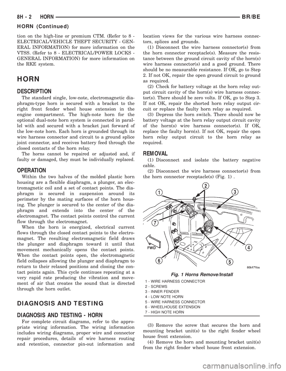
The standard single, low-note, electromagnetic dia-
phragm-type horn is secured with a bracket to the
right front fender wheel house extension in the
engine compartment. The high-note horn for the
optional dual-note horn system is connected in paral-
lel with and secured with a bracket just forward of
the low-note horn. Each horn is grounded through its
wire harness connector and circuit to a ground splice
joint connector, and receives battery feed through the
closed contacts of the horn relay.
The horns cannot be repaired or adjusted and, if
faulty or damaged, they must be individually replaced.
OPERATION
Within the two halves of the molded plastic horn
housing are a flexible diaphragm, a plunger, an elec-
tromagnetic coil and a set of contact points. The dia-
phragm is secured in suspension around its
perimeter by the mating surfaces of the horn hous-
ing. The plunger is secured to the center of the dia-
phragm and extends into the center of the
electromagnet. The contact points control the current
flow through the electromagnet.
When the horn is energized, electrical current
flows through the closed contact points to the electro-
magnet. The resulting electromagnetic field draws
the plunger and diaphragm toward it until that
movement mechanically opens the contact points.
When the contact points open, the electromagnetic
field collapses allowing the plunger and diaphragm to
return to their relaxed positions and closing the con-
tact points again. This cycle continues repeating at a
very rapid rate producing the vibration and move-
ment of air that creates the sound that is directed
through the horn outlet.
DIAGNOSIS AND TESTING
DIAGNOSIS AND TESTING - HORN
For complete circuit diagrams, refer to the appro-
priate wiring information. The wiring information
includes wiring diagrams, proper wire and connector
repair procedures, details of wire harness routing
and retention, connector pin-out information andlocation views for the various wire harness connec-
tors, splices and grounds.
(1) Disconnect the wire harness connector(s) from
the horn connector receptacle(s). Measure the resis-
tance between the ground circuit cavity of the horn(s)
wire harness connector(s) and a good ground. There
should be no measurable resistance. If OK, go to Step
2. If not OK, repair the open ground circuit to ground
as required.
(2) Check for battery voltage at the horn relay out-
put circuit cavity of the horn(s) wire harness connec-
tor(s). There should be zero volts. If OK, go to Step 3.
If not OK, repair the shorted horn relay output cir-
cuit or replace the faulty horn relay as required.
(3) Depress the horn switch. There should now be
battery voltage at the horn relay output circuit cavity
of the horn(s) wire harness connector(s). If OK,
replace the faulty horn(s). If not OK, repair the open
horn relay output circuit to the horn relay as
required.
REMOVAL
(1) Disconnect and isolate the battery negative
cable.
(2) Disconnect the wire harness connector(s) from
the horn connector receptacle(s) (Fig. 1) .
(3) Remove the screw that secures the horn and
mounting bracket unit(s) to the right fender wheel
house front extension.
(4) Remove the horn and mounting bracket unit(s)
from the right fender wheel house front extension.
Fig. 1 Horns Remove/Install
1 - WIRE HARNESS CONNECTOR
2 - SCREWS
3 - INNER FENDER
4 - LOW NOTE HORN
5 - WIRE HARNESS CONNECTOR
6 - WHEELHOUSE EXTENSION
7 - HIGH NOTE HORN
8H - 2 HORNBR/BE
HORN (Continued)
Page 1595 of 2889
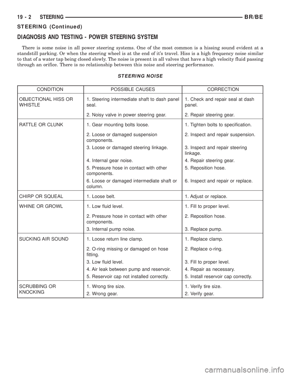
DIAGNOSIS AND TESTING - POWER STEERING SYSTEM
There is some noise in all power steering systems. One of the most common is a hissing sound evident at a
standstill parking. Or when the steering wheel is at the end of it's travel. Hiss is a high frequency noise similar
to that of a water tap being closed slowly. The noise is present in all valves that have a high velocity fluid passing
through an orifice. There is no relationship between this noise and steering performance.
STEERING NOISE
CONDITION POSSIBLE CAUSES CORRECTION
OBJECTIONAL HISS OR
WHISTLE1. Steering intermediate shaft to dash panel
seal.1. Check and repair seal at dash
panel.
2. Noisy valve in power steering gear. 2. Repair steering gear.
RATTLE OR CLUNK 1. Gear mounting bolts loose. 1. Tighten bolts to specification.
2. Loose or damaged suspension
components.2. Inspect and repair suspension.
3. Loose or damaged steering linkage. 3. Inspect and repair steering
linkage.
4. Internal gear noise. 4. Repair steering gear.
5. Pressure hose in contact with other
components.5. Reposition hose.
6. Loose or damaged intermediate shaft or
column.6. Inspect and repair or replace.
CHIRP OR SQUEAL 1. Loose belt. 1. Adjust or replace.
WHINE OR GROWL 1. Low fluid level. 1. Fill to proper level.
2. Pressure hose in contact with other
components.2. Reposition hose.
3. Internal pump noise. 3. Replace pump.
SUCKING AIR SOUND 1. Loose return line clamp. 1. Replace clamp.
2. O-ring missing or damaged on hose
fitting.2. Replace o-ring.
3. Low fluid level. 3. Fill to proper level.
4. Air leak between pump and reservoir. 4. Repair as necessary.
5. Reservoir cap not installed correctly. 5. Install reservoir cap correctly.
SCRUBBING OR
KNOCKING1. Wrong tire size. 1. Verify tire size.
2. Wrong gear. 2. Verify gear.
19 - 2 STEERINGBR/BE
STEERING (Continued)