manual radio set DODGE RAM 2001 Service Repair Manual
[x] Cancel search | Manufacturer: DODGE, Model Year: 2001, Model line: RAM, Model: DODGE RAM 2001Pages: 2889, PDF Size: 68.07 MB
Page 425 of 2889
Refer to Electrical, Restraints for more information
on the clockspring. Refer to Electrical, Body Control/
Central Control Module for more information on the
Central Timer Module. Refer to the appropriate wir-
ing information. The wiring information includes wir-
ing diagrams, proper wire and connector repair
procedures, details of wire harness routing and
retention, connector pin-out information and location
views for the various wire harness connectors, splices
and grounds. Following are general descriptions of
the remaining major components in the standard and
optional factory-installed audio systems.
OPERATION
See the owner's manual in the vehicle glove box for
more information on the features, use and operation
of each of the available audio systems.
CENTRAL TIMER MODULE
The high-line or premium Central Timer Module
(CTM) can also control some features of the audio
system when the vehicle is equipped with the
optional RAZ radio receiver and remote radio
switches. A high-line CTM is used on high-line ver-
sions of this vehicle. A premium CTM is used on
vehicles equipped with the optional heated seats. The
CTM combines the functions of a chime/buzzer mod-
ule, an intermittent wipe module, an illuminated
entry module, a remote keyless entry module, and a
vehicle theft security system module in a single unit.
The high-line or premium CTM also controls and
integrates many of the additional electronic functions
and features included on models with this option.The RAZ radio receiver with a remote radio switch
option is one of the features that the CTM controls.
The CTM is programmed to send switch status mes-
sages over the Chrysler Collision Detection (CCD)
data bus to control the volume, seek, and pre-set sta-
tion advance functions of the RAZ radio receiver. The
CTM monitors the status of the remote radio
switches located on the steering wheel through a
hard wired circuit. The CTM then sends the proper
switch status messages to the radio receiver. The
electronic circuitry within the radio receiver responds
to the switch status messages it receives by adjusting
the radio settings as requested.
Refer to Electrical, Body Control/Central Timer
Module for more information on the high-line CTM.
Refer to Remote Radio Switch in Description and
Operation for more information on this component.
In addition, radio receivers connected to the CCD
data bus have several audio system functions that
can be diagnosed using a DRBIIItscan tool. Refer to
the proper Diagnostic Procedures manual for more
information on DRBIIIttesting of the audio systems.
DIAGNOSIS AND TESTING - AUDIO
WARNING: ON VEHICLES EQUIPPED WITH AIR-
BAGS, REFER TO ELECTRICAL, RESTRAINTS
BEFORE ATTEMPTING ANY STEERING WHEEL,
STEERING COLUMN, OR INSTRUMENT PANEL
COMPONENT DIAGNOSIS OR SERVICE. FAILURE
TO TAKE THE PROPER PRECAUTIONS COULD
RESULT IN ACCIDENTAL AIRBAG DEPLOYMENT
AND POSSIBLE PERSONAL INJURY.
8A - 2 AUDIOBR/BE
AUDIO (Continued)
Page 433 of 2889
(7) Remove the radio receiver from the instrument
panel. Refer to Audio, Radio for the procedures.
(8) Pull the antenna cable out through the radio
receiver opening in the instrument panel.
(9) Untie the cord or twine from the instrument
panel antenna cable connector, leaving the cord or
twine in place of the cable in the instrument panel.
(10) Remove the antenna cable from the instru-
ment panel.
INSTALLATION
(1) Tie the end of the cord or twine that was used
during instrument panel antenna cable removal
securely to the connector on the end of the antenna
cable being installed into the instrument panel. This
cord will be used to pull or ªfishº the cable back into
position.
(2) Using the cord or twine, pull the antenna cable
through the radio receiver opening from under the
instrument panel.
(3) Install the radio receiver onto the instrument
panel. Refer to Audio, Radio for the procedures.
(4) Reach through the glove box opening to engage
the antenna cable with the retainer clips on the back
of the instrument panel.
(5) Install the glove box onto the instrument panel.
Refer to Body, Instrument Panel for the procedures.
(6) Untie the cord or twine from the instrument
panel antenna cable connector.
(7) Reach under the passenger side of the instru-
ment panel near the right cowl side inner panel to
reconnect the two halves of the radio antenna coaxial
cable connector. Wrap the connection with a piece of
foam tape.
(8) Engage the coaxial cable connector with the
retainer clip located on the bottom of the heater-A/C
housing.
(9) Reconnect the battery negative cable.
RADIO
DESCRIPTION
Available factory-installed radio receivers for this
model include an AM/FM/cassette (RAS sales code),
an AM/FM/cassette/5-band graphic equalizer with CD
changer control feature (RBN sales code), an AM/FM/
CD/3-band graphic equalizer (RBR sales code), or an
AM/FM/CD/cassette/3-band graphic equalizer (RAZ
sales code). The factory-installed RAZ sales code
radio receivers can also communicate on the Chrysler
Collision Detection (CCD) data bus network through
a separate two-way wire harness connector. All facto-
ry-installed receivers are stereo Electronically Tuned
Radios (ETR) and include an electronic digital clock
function.These radio receivers can only be serviced by an
authorized radio repair station. See the latest War-
ranty Policies and Procedures manual for a current
listing of authorized radio repair stations.
All vehicles are equipped with an Ignition-Off
Draw (IOD) fuse that is removed when the vehicle is
shipped from the factory. This fuse feeds various
accessories that require battery current when the
ignition switch is in the Off position, including the
clock. The IOD fuse is removed to prevent battery
discharge during vehicle storage.
When removing or installing the IOD fuse, it is
important that the ignition switch be in the Off posi-
tion. Failure to place the ignition switch in the Off
position can cause the radio display to become scram-
bled when the IOD fuse is removed and replaced.
Removing and replacing the IOD fuse again, with the
ignition switch in the Off position, will correct the
scrambled display condition.
The IOD fuse should be checked if the radio or
clock displays are inoperative. The IOD fuse is
located in the junction block. Refer to the fuse layout
label on the back of the instrument panel fuse access
panel for IOD fuse identification and location.
OPERATION
The radio receiver operates on fused battery cur-
rent that is available only when the ignition switch is
in the On or Accessory positions. The electronic digi-
tal clock function of the radio operates on fused bat-
tery current supplied through the IOD fuse,
regardless of the ignition switch position.
For more information on the features, setting pro-
cedures, and control functions for each of the avail-
able factory-installed radio receivers, see the owner's
manual in the vehicle glove box. For complete circuit
diagrams, refer to the appropriate wiring informa-
tion. The wiring information includes wiring dia-
grams, proper wire and connector repair procedures,
details of wire harness routing and retention, connec-
tor pin-out information and location views for the
various wire harness connectors, splices and grounds.
DIAGNOSIS AND TESTING
DIAGNOSIS AND TESTING - RADIO
If the vehicle is equipped with the optional remote
radio switches located on the steering wheel and the
problem being diagnosed is related to one of the
symptoms listed below, be certain to check the
remote radio switches and circuits. Refer to Audio,
Remote Radio Switch prior to attempting radio diag-
nosis or repair.
²Stations changing with no remote radio switch
input
8A - 10 AUDIOBR/BE
INSTRUMENT PANEL ANTENNA CABLE (Continued)
Page 438 of 2889
(6) Remove the heater core ground strap from the
top of the heater-A/C housing.
INSTALLATION
(1) Position the heater core ground strap and the
heater core tube retaining strap to the top of the
heater-A/C housing.
(2) Install and tighten the screw that secures the
heater core ground strap eyelet and the heater core
tube retaining strap to the top of the heater-A/C
housing. Tighten the screw to 2.2 N´m (20 in. lbs.).
(3) Position the heater core ground strap eyelet
over the stud on the dash panel.
(4) Install and tighten the nut that secures the
heater core ground strap eyelet to the stud on the
dash panel. Tighten the nut to 3.9 N´m (35 in. lbs.).
(5) Install the glove box onto the instrument panel.
Refer to Body, Instrument Panel for the procedures.
(6) Reconnect the battery negative cable.
REMOTE SWITCHES
DESCRIPTION
A remote radio switch option is available on models
equipped with the AM/FM/CD/cassette/3-band
graphic equalizer (RAZ sales code) radio receiver and
the high-line Central Timer Module (CTM). Refer to
Electrical, Body Control/Central Timer Module for
more information on this component.
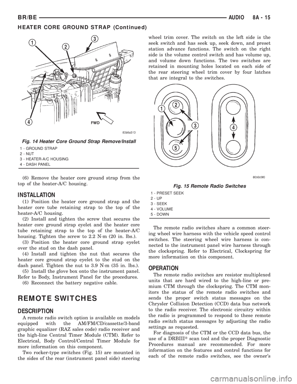
Two rocker-type switches (Fig. 15) are mounted in
the sides of the rear (instrument panel side) steeringwheel trim cover. The switch on the left side is the
seek switch and has seek up, seek down, and preset
station advance functions. The switch on the right
side is the volume control switch and has volume up,
and volume down functions. The two switches are
retained in mounting holes located on each side of
the rear steering wheel trim cover by four latches
that are integral to the switches.
The remote radio switches share a common steer-
ing wheel wire harness with the vehicle speed control
switches. The steering wheel wire harness is con-
nected to the instrument panel wire harness through
the clockspring. Refer to Electrical, Clockspring for
more information on this component.
OPERATION
The remote radio switches are resistor multiplexed
units that are hard wired to the high-line or pre-
mium CTM through the clockspring. The CTM mon-
itors the status of the remote radio switches and
sends the proper switch status messages on the
Chrysler Collision Detection (CCD) data bus network
to the radio receiver. The electronic circuitry within
the radio is programmed to respond to these remote
radio switch status messages by adjusting the radio
settings as requested.
For diagnosis of the CTM or the CCD data bus, the
use of a DRBIIItscan tool and the proper Diagnostic
Procedures manual are recommended. For more
information on the features and control functions for
each of the remote radio switches, see the owner's
Fig. 14 Heater Core Ground Strap Remove/Install
1 - GROUND STRAP
2 - NUT
3 - HEATER-A/C HOUSING
4 - DASH PANEL
Fig. 15 Remote Radio Switches
1 - PRESET SEEK
2-UP
3 - SEEK
4 - VOLUME
5 - DOWN
BR/BEAUDIO 8A - 15
HEATER CORE GROUND STRAP (Continued)
Page 439 of 2889
manual in the vehicle glove box. For complete circuit
diagrams, refer to the appropriate wiring informa-
tion. The wiring information includes wiring dia-
grams, proper wire and connector repair procedures,
details of wire harness routing and retention, connec-
tor pin-out information and location views for the
various wire harness connectors, splices and grounds.
DIAGNOSIS AND TESTING
DIAGNOSIS AND TESTING - REMOTE
SWITCHES
For complete circuit diagrams, refer to the appro-
priate wiring information. The wiring information
includes wiring diagrams, proper wire and connector
repair procedures, details of wire harness routing
and retention, connector pin-out information and
location views for the various wire harness connec-
tors, splices and grounds.
WARNING: ON VEHICLES EQUIPPED WITH AIR-
BAGS, REFER TO ELECTRICAL, RESTRAINTS
BEFORE ATTEMPTING ANY STEERING WHEEL,
STEERING COLUMN, OR INSTRUMENT PANEL
COMPONENT DIAGNOSIS OR SERVICE. FAILURE
TO TAKE THE PROPER PRECAUTIONS COULD
RESULT IN ACCIDENTAL AIRBAG DEPLOYMENT
AND POSSIBLE PERSONAL INJURY.
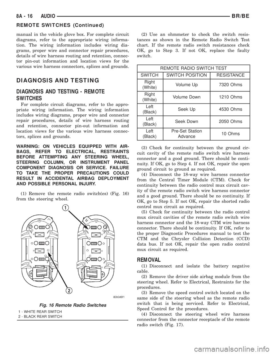
(1) Remove the remote radio switch(es) (Fig. 16)
from the steering wheel.(2) Use an ohmmeter to check the switch resis-
tances as shown in the Remote Radio Switch Test
chart. If the remote radio switch resistances check
OK, go to Step 3. If not OK, replace the faulty
switch.
REMOTE RADIO SWITCH TEST
SWITCH SWITCH POSITION RESISTANCE
Right
(White)Volume Up 7320 Ohms
Right
(White)Volume Down 1210 Ohms
Left
(Black)Seek Up 4530 Ohms
Left
(Black)Seek Down 2050 Ohms
Left
(Black)Pre-Set Station
Advance10 Ohms
(3) Check for continuity between the ground cir-
cuit cavity of the remote radio switch wire harness
connector and a good ground. There should be conti-
nuity. If OK, go to Step 4. If not OK, repair the open
ground circuit to ground as required.
(4) Disconnect the 18-way wire harness connector
from the Central Timer Module (CTM). Check for
continuity between the radio control mux circuit cav-
ity of the remote radio switch wire harness connector
and a good ground. There should be no continuity. If
OK, go to Step 5. If not OK, repair the shorted radio
control mux circuit as required.
(5) Check for continuity between the radio control
mux circuit cavities of the remote radio switch wire
harness connector and the 18-way CTM wire harness
connector. There should be continuity. If OK, refer to
the proper Diagnostic Procedures manual to test the
CTM and the Chrysler Collision Detection (CCD)
data bus. If not OK, repair the open radio control
mux circuit as required.
REMOVAL
(1) Disconnect and isolate the battery negative
cable.
(2) Remove the driver side airbag module from the
steering wheel. Refer to Electrical, Restraints for the
procedures.
(3) Remove the speed control switch located on the
same side of the steering wheel as the remote radio
switch that is being serviced. Refer to Electrical,
Speed Control for the procedures.
(4) Disconnect the steering wheel wire harness
connector from the connector receptacle of the remote
radio switch (Fig. 17).
Fig. 16 Remote Radio Switches
1 - WHITE REAR SWITCH
2 - BLACK REAR SWITCH
8A - 16 AUDIOBR/BE
REMOTE SWITCHES (Continued)
Page 487 of 2889
A vehicle that has not been operated for approxi-
mately twenty days, may discharge the battery to an
inadequate level. When a vehicle will not be used for
twenty days or more (stored), remove the IOD fuse
from the Power Distribution Center (PDC). This will
reduce battery discharging.
Excessive IOD can be caused by:
²Electrical items left on.
²Faulty or improperly adjusted switches.
²Faulty or shorted electronic modules and compo-
nents.
²An internally shorted generator.
²Intermittent shorts in the wiring.If the IOD is over thirty-five milliamperes, the
problem must be found and corrected before replac-
ing a battery. In most cases, the battery can be
charged and returned to service after the excessive
IOD condition has been corrected.
(1) Verify that all electrical accessories are off.
Turn off all lamps, remove the ignition key, and close
all doors. If the vehicle is equipped with an illumi-
nated entry system or an electronically tuned radio,
allow the electronic timer function of these systems
to automatically shut off (time out). This may take
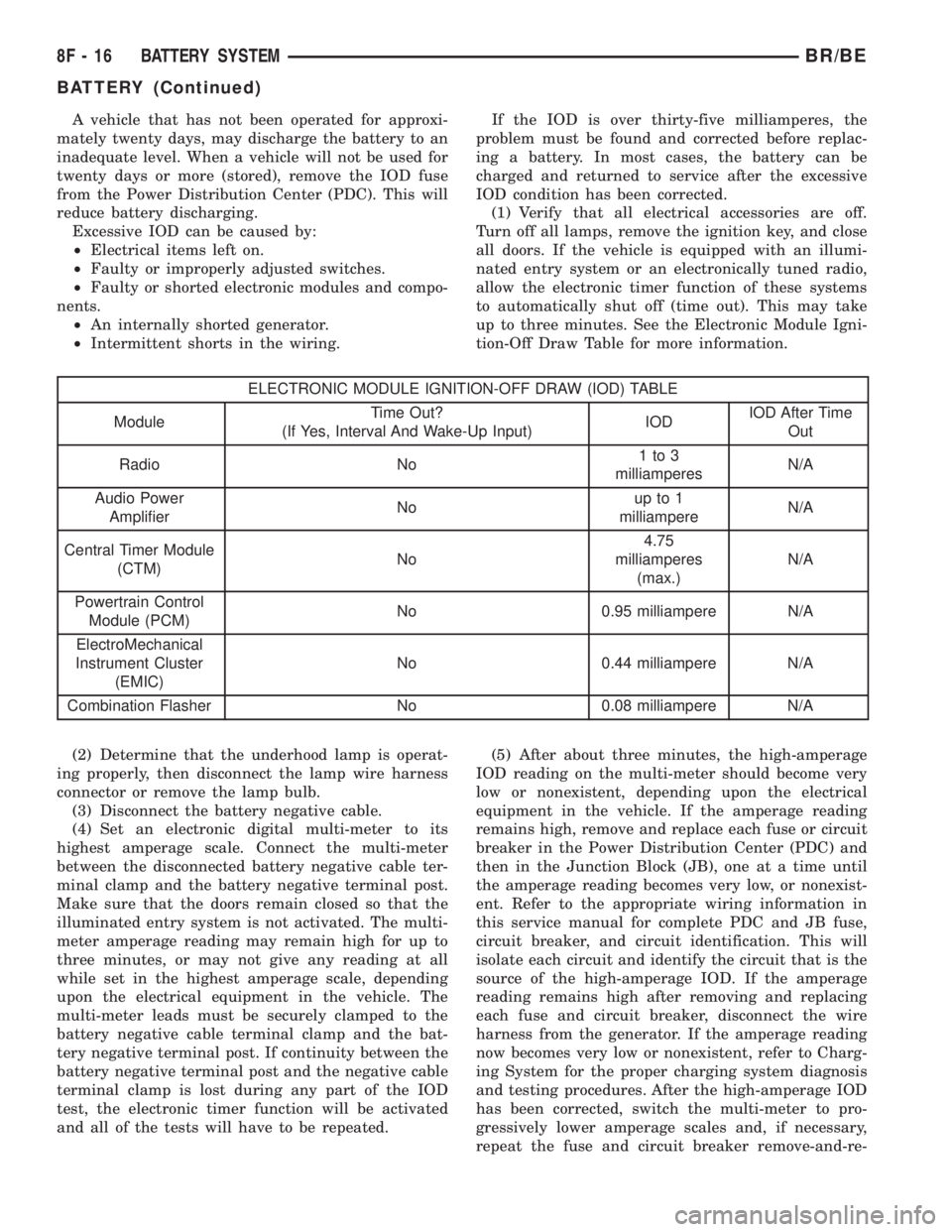
up to three minutes. See the Electronic Module Igni-
tion-Off Draw Table for more information.
ELECTRONIC MODULE IGNITION-OFF DRAW (IOD) TABLE
ModuleTime Out?
(If Yes, Interval And Wake-Up Input)IODIOD After Time
Out
Radio No1to3
milliamperesN/A
Audio Power
AmplifierNoup to 1
milliampereN/A
Central Timer Module
(CTM)No4.75
milliamperes
(max.)N/A
Powertrain Control
Module (PCM)No 0.95 milliampere N/A
ElectroMechanical
Instrument Cluster
(EMIC)No 0.44 milliampere N/A
Combination Flasher No 0.08 milliampere N/A
(2) Determine that the underhood lamp is operat-
ing properly, then disconnect the lamp wire harness
connector or remove the lamp bulb.
(3) Disconnect the battery negative cable.
(4) Set an electronic digital multi-meter to its
highest amperage scale. Connect the multi-meter
between the disconnected battery negative cable ter-
minal clamp and the battery negative terminal post.
Make sure that the doors remain closed so that the
illuminated entry system is not activated. The multi-
meter amperage reading may remain high for up to
three minutes, or may not give any reading at all
while set in the highest amperage scale, depending
upon the electrical equipment in the vehicle. The
multi-meter leads must be securely clamped to the
battery negative cable terminal clamp and the bat-
tery negative terminal post. If continuity between the
battery negative terminal post and the negative cable
terminal clamp is lost during any part of the IOD
test, the electronic timer function will be activated
and all of the tests will have to be repeated.(5) After about three minutes, the high-amperage
IOD reading on the multi-meter should become very
low or nonexistent, depending upon the electrical
equipment in the vehicle. If the amperage reading
remains high, remove and replace each fuse or circuit
breaker in the Power Distribution Center (PDC) and
then in the Junction Block (JB), one at a time until
the amperage reading becomes very low, or nonexist-
ent. Refer to the appropriate wiring information in
this service manual for complete PDC and JB fuse,
circuit breaker, and circuit identification. This will
isolate each circuit and identify the circuit that is the
source of the high-amperage IOD. If the amperage
reading remains high after removing and replacing
each fuse and circuit breaker, disconnect the wire
harness from the generator. If the amperage reading
now becomes very low or nonexistent, refer to Charg-
ing System for the proper charging system diagnosis
and testing procedures. After the high-amperage IOD
has been corrected, switch the multi-meter to pro-
gressively lower amperage scales and, if necessary,
repeat the fuse and circuit breaker remove-and-re-
8F - 16 BATTERY SYSTEMBR/BE
BATTERY (Continued)
Page 522 of 2889
²If both indicator lamps for a heated seat switch
operate, but the heated seat elements do not heat,
refer toHeated Seat Modulein Electronic Control
Modules for the location of the proper heated seat
module diagnosis and testing procedures. Also refer
to the Body Diagnostic Manual for additional diagno-
sis and testing procedures.
²If none of the indicator lamps for both heated
seat switches will operate and the heated seat ele-
ments for both seats do not heat, refer toHeated
Seat Relayin this section for the location of the
proper heated seat relay diagnosis and testing proce-
dures.
²If the an indicator lamp on either heated seat
switch remains illuminated after the heated seat has
been turned Off, refer toHeated Seat Modulein
Electronic Control Modules for the location of the
proper heated seat module diagnosis and testing pro-
cedures. Also refer to the Body Diagnostic Manual for
additional diagnosis and testing procedures.
DRIVER SEAT HEATER
SWITCH
DESCRIPTION
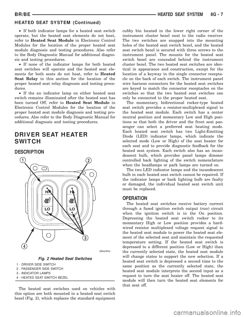
The heated seat switches used on vehicles with
this option are both mounted in a heated seat switch
bezel (Fig. 2), which replaces the standard equipmentcubby bin located in the lower right corner of the
instrument cluster bezel next to the radio receiver.
The two switches are snapped into the mounting
holes of the heated seat switch bezel, and the heated
seat switch bezel is secured with three screws to the
instrument panel. The mounts for the heated seat
switch bezel are concealed behind the instrument
cluster bezel. The two heated seat switches are iden-
tical in appearance and construction, except for the
location of a keyway in the single connector recepta-
cle on the back of each switch. The instrument panel
wire harness connectors for the heated seat switches
are keyed to match the connector receptacles on the
switches so that the two heated seat switches can
only be connected to the proper heated seat.
The momentary, bidirectional rocker-type heated
seat switch provides a resistor-multiplexed signal to
the heated seat module. Each switch has a center
neutral position and momentary Low and High posi-
tions so that both the driver and the front seat pas-
senger can select a preferred seat heating mode.
Each heated seat switch has two Light-Emitting
Diode (LED) indicator lamps, which indicate the
selected mode (Low or High) of the seat heater for
each seat and to provide diagnostic feedback for the
heated seat system. Each switch also has an incan-
descent bulb, which provides panel lamps dimmer
controlled back lighting of the switch nomenclature
when the headlamps or park lamps are turned on.
The two LED indicator lamps and the incandescent
bulb in each heated seat switch cannot be repaired. If
the indicator lamps or back lighting bulb are faulty
or damaged, the individual heated seat switch unit
must be replaced.
OPERATION
The heated seat switches receive battery current
through a fused ignition switch output (run) circuit
when the ignition switch is in the On position.
Depressing the heated seat switch rocker to its
momentary High or Low position provides a hard-
wired resistor multiplexed voltage request signal to
the heated seat module to power the heated seat ele-
ment of the selected seat and maintain the requested
temperature setting. If the heated seat switch is
depressed to a different position (Low or High) than
the currently selected state, the heated seat module
will change states to support the new selection. If a
heated seat switch is depressed a second time to the
same position as the currently selected state, the
heated seat module interprets the second input as a
request to turn the seat heater off. The heated seat
module will then turn the heated seat elements for
that seat off.
Fig. 2 Heated Seat Switches
1 - DRIVER SIDE SWITCH
2 - PASSENGER SIDE SWITCH
3 - INDICATOR LAMPS
4 - HEATED SEAT SWITCH BEZEL
BR/BEHEATED SEAT SYSTEM 8G - 7
HEATED SEAT SYSTEM (Continued)
Page 2828 of 2889
Items found requiring adjustment and/or repair
should be corrected before delivery of the vehicle.
NOTE: It is the dealer's responsibility to protect
new vehicles from damage and deterioration prior
to retail delivery both before and after new vehicle
preparation.
The information includes the following features:
Inspection points are cross-referenced to the New
Vehicle Preparation Form as follows:
²Titles indicate the general area being inspected
or the types of checks being made (i.e., underhood,
body-exterior, road test, etc.).
²Sub-Titles identify the types of items to be
inspected in that area (i.e., lines/hoses, wiring, etc.).
Procedures follow a logical order to prevent dupli-
cation and wasted effort.
Tips to help you do a better job are found as
NOTES.
RECEIVING
INSPECTION
The following procedures are recommended for
your own protection upon receipt of new vehicles.
When a new car is delivered by the carrier, it should
be inspected to ensure that it is in good condition
and to determine if there is any shortage or transpor-
tation damage.
EXTERIOR
Upon receipt of a new vehicle, check immediately
for:
²Under carriage damage
²Chipped or cracked windshield, broken windows,
and loose or missing moldings and name-plates
²Dents, scrapes, scratches, chips, dirt in paints or
other damage to the body exterior
²Damaged or missing side view mirror(s)
²Missing wheel nuts
²Broken or missing lenses
²Chafing, bruises, cuts, or scrapes on tire side-
walls or tread
²Missing underhood items
²Missing fuel filler cap
²Shipped loose items-license plate bracket, spare
tire, jack and tire wrench, radio antenna, floor mats,
wheel covers, cargo nets, fuses and other items²Ensure that IOD fuse is removed
²Check battery test indicator when easily visible,
or use voltmeter (battery must be at 12.4 volts or
greater). Charge to ensure green dot-visibility, per-
manent damage may occur if battery remains in a
discharged state for any length of time.
INTERIOR
Check interior items such as:
²Rearview mirror
²Accessory control knobs
²Smokers package items
²Keys
²Radio
²Special equipment items listed on shipper
²Owner's Manual and Consumer information Bro-
chures (normally stored in the glove box).
²Cuts, abrasions or stains on interior trim.
NOTE: Remember a careful look at new vehicles
when they are received may prevent problems when
preparing vehicles for delivery to your customers.
MAJOR INSPECTION POINTS
(1) Check operation of hood latch and safety catch-
adjust as required.
(2) Check all fluids for proper level and top off
with the proper fluid as required-engine oil, auto-
matic transmission fluid, brake master cylinder,
clutch master cylinder, power steering, windshield
washer, and cooling system. (Vehicle must be at nor-
mal operating temperature for some of these checks.)
(3) Check brake, clutch, fuel, and power steering
lines and hoses for leaks and clearance from moving
and hot objects-reroute to the proper location and
tighten as required.
(4) Check battery state of charge-recharge if neces-
sary, to ensure green dot is visible or instrument
panel voltmeter indicates 12.4 volts or greater.
(5) Check routing and connections of underhood
wiring, vacuum hoses, refrigerant lines and coolant
hoses for leaks, loose connections and clearance from
moving objects reroute and tighten connections as
required. Install IOD fuse on applicable vehicles.
NOTE: Reset radio, clock, compass, etc., after
installing, if vehicle is being delivered.
BR/BENEW VEHICLE PREPARATION 30 - 3
INTRODUCTION (Continued)
Page 2840 of 2889
ROAD TEST
DESCRIPTION - ROAD TEST INSPECTION
The following items must be inspected during the
road test portion of the new vehicle inspection.
²Check neutral safety switch operation
²Check operation of shift/clutch interlock system
²Check operation of gauges and warning lights
²Check horn operation
²Check operation of turn signals and emergency
flashers
²Check all mirror adjustments, including day/
night function
²Check windshield wipers for proper wipe pattern
and intermittent mode (if equipped)
²Check washer spray pattern
²Check heater, defroster and air conditioning for
proper operation
²Check that the fan operates quietly
²Check the rear window defroster (if equipped)
²Leave air selection lever in the fresh air position
²Check the rear heater and air conditioning for
proper operation
²Check the rear air register locations
²Check that the indicator lamps operate properly
²Check the operation of the radio, cassette and/or
compact disc player, and that sound quality is good
²Ensure that the clock displays the correct time
²Check that the trip computer/maintenance
reminder operates in all modes
²Check all speed control functions
²Check the service brakes to ensure that they
stop the vehicle in a straight line, without noise,
shudder or vibration
²Check the brake warning light
²Check the parking brake operation
²Check the engine's performance
²Check the transmission's performance for
smooth, quiet operation. If the vehicle is a 4x4, check
that the transfer case shifts easily among all ranges
²Check Autostick function (if equipped)
²Check the vehicle's steering and handling
²The steering wheel should be centered when
traveling in a straight line
²The vehicle should not pull or vibrate
²Check for squeaks, rattles and wind noise
²Check any other vehicle aspects you believe are
important, but that may not be included on the New
Vehicle Preparation Form
²Fill fuel tank with specified grade of fuel
INSPECTION - FUEL
Fill fuel tank with specified grade of gasoline (reg-
ular, midgrade or premium).
INSPECTION - OTHER
As part of DaimlerChrysler's Customer One philos-
ophy, the ªOtherº blank is provided on the New Vehi-
cle Preparation Form. This is designed to encourage
you to check any aspects of vehicle operation that
you believe are important to your customers, but that
do not appear elsewhere on the form.
INSPECTION - SQUEAKS, RATTLES AND WIND
NOISE
(1) Make sure that the instrument panel, glove
box, seats, steering wheel and column are free from
squeaks and rattles. Tighten any obvious loose fas-
teners.
(2) Check that the windows and doors are free
from squeaks, rattles and wind noise.
(3) Check that the vehicle exterior is free from
squeaks, rattles and noise, front and rear.
(4) Make sure that all interior panels are free from
squeaks and rattles.
INSPECTION - STEERING AND HANDLING
(1) Check that the power assist works properly (if
equipped). Steering should not require excessive
effort.
(2) Make sure the steering wheel does not vibrate
at idle or road speed.
(3) Ensure that the steering wheel is centered
when traveling straight ahead.
(4) Check that the vehicle does not drift to one
side.
(5) Make sure that the vehicle does not vibrate/
shake.
INSPECTION - TRANSMISSION/TRANSFER
CASE
AUTOMATIC TRANSMISSION
(1) Make sure that the park lock holds the vehicle
With the vehicle on a grade, put automatic trans-
mission in PARK and slowly release the service
brake to see if park lock holds. If it does not hold, the
transmission requires further service.
(2) Make sure shift lever operates easily/ smoothly
(Fig. 36).
Check for smooth shifting. Check for proper
upshifting and downshifting.
MANUAL TRANSMISSION
(1) Check that the shifter operates easily (Fig. 38).
(2) Make sure that the clutch operates smoothly
(Fig. 37).
(3) Look for proper synchronization.
The gears should not grind.
BR/BENEW VEHICLE PREPARATION 30 - 15