trip computer DODGE RAM 2001 Service Repair Manual
[x] Cancel search | Manufacturer: DODGE, Model Year: 2001, Model line: RAM, Model: DODGE RAM 2001Pages: 2889, PDF Size: 68.07 MB
Page 462 of 2889
the module attempts to have the CCD chip re-send
the message.
DIAGNOSIS AND TESTING - CCD DATA BUS
CCD BUS FAILURE
The CCD data bus can be monitored using the
DRBIIItscan tool. However, it is possible for the
data bus to pass all tests since the voltage parame-
ters will be in ªrangeª and false signals are being
sent. There are essentially 12 ªhard failuresª that
can occur with the CCD data bus:
²Bus Shorted to Battery
²Bus Shorted to 5 Volts
²Bus Shorted to Ground
²Bus (+) Shorted to Bus (±)
²Bus (±) and Bus (+) Open
²Bus (+) Open
²Bus (±) Open
²No Bus Bias
²Bus Bias Level Too High
²Bus Bias Level Too Low
²No Bus Termination
²Not Receiving Bus Messages Correctly
Refer to the appropriate diagnostic procedures for
details on how to diagnose these faults using a
DRBIIItscan tool.
BUS FAILURE VISUAL SYMPTOM DIAGNOSIS
The following visible symptoms or customer com-
plaints, alone or in combination, may indicate a CCD
data bus failure:
²Airbag Indicator Lamp and Malfuntion Indicator
Lamp (MIL) Illuminated
²Instrument Cluster Gauges (All) Inoperative
²No Compass Mini-Trip Computer (CMTC) Oper-
ation
CONTROLLER ANTILOCK
BRAKE
DESCRIPTION
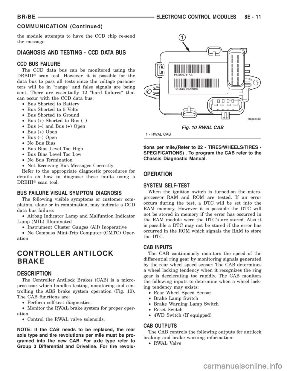
The Controller Antilock Brakes (CAB) is a micro-
processor which handles testing, monitoring and con-
trolling the ABS brake system operation (Fig. 10).
The CAB functions are:
²Perform self-test diagnostics.
²Monitor the RWAL brake system for proper oper-
ation.
²Control the RWAL valve solenoids.
NOTE: If the CAB needs to be replaced, the rear
axle type and tire revolutions per mile must be pro-
gramed into the new CAB. For axle type refer to
Group 3 Differential and Driveline. For tire revolu-tions per mile,(Refer to 22 - TIRES/WHEELS/TIRES -
SPECIFICATIONS) . To program the CAB refer to the
Chassis Diagnostic Manual.
OPERATION
SYSTEM SELF-TEST
When the ignition switch is turned-on the micro-
processor RAM and ROM are tested. If an error
occurs during the test, a DTC will be set into the
RAM memory. However it is possible the DTC will
not be stored in memory if the error has occurred in
the RAM module were the DTC's are stored. Also it
is possible a DTC may not be stored if the error has
occurred in the ROM which signals the RAM to store
the DTC.
CAB INPUTS
The CAB continuously monitors the speed of the
differential ring gear by monitoring signals generated
by the rear wheel speed sensor. The CAB determines
a wheel locking tendency when it recognizes the ring
gear is decelerating too rapidly. The CAB monitors
the following inputs to determine when a wheel lock-
ing tendency may exists:
²Rear Wheel Speed Sensor
²Brake Lamp Switch
²Brake Warning Lamp Switch
²Reset Switch
²4WD Switch (If equipped)
CAB OUTPUTS
The CAB controls the following outputs for antilock
braking and brake warning information:
²RWAL Valve
Fig. 10 RWAL CAB
1-RWALCAB
BR/BEELECTRONIC CONTROL MODULES 8E - 11
COMMUNICATION (Continued)
Page 564 of 2889

The VFD is diagnosed using the EMIC self-diag-
nostic actuator test. (Refer to 8 - ELECTRICAL/IN-
STRUMENT CLUSTER - DIAGNOSIS AND
TESTING). Proper testing of the CCD data bus and
the data bus message inputs to the EMIC that con-
trol some of the VFD functions requires the use of a
DRBIIItscan tool. Refer to the appropriate diagnos-
tic information. Specific operation details for the
odometer and trip odometer functions of the VFD
may be found elsewhere in this service manual.
INDICATORS
Indicators are located in various positions within
the EMIC and are all connected to the EMIC circuit
board. The four-wheel drive indicator, high beam
indicator, washer fluid indicator, turn signal indica-
tors, and wait-to-start indicator are hard wired. The
brake indicator is controlled by CCD data bus mes-
sages from the Controller Anti-lock Brake (CAB) and
the hard wired park brake switch input to the EMIC.
The seatbelt indicator is controlled by the EMIC pro-
gramming, CCD data bus messages from the Airbag
Control Module (ACM), and the hard wired seat belt
switch input to the EMIC. The Malfunction Indicator
Lamp (MIL) is normally controlled by CCD data bus
messages from the Powertrain Control Module
(PCM); however, if the EMIC loses CCD data bus
communications, the EMIC circuitry will automati-
cally turn the MIL on, and flash the odometer VFD
on and off repeatedly until CCD data bus communi-
cation is restored. The EMIC uses CCD data bus
messages from the Powertrain Control Module
(PCM), the diesel engine only Engine Control Module
(ECM), the ACM, and the CAB to control all of the
remaining indicators. Different indicators are con-
trolled by different strategies; some receive fused
ignition switch output from the EMIC circuitry clus-
ter and have a switched ground, while others are
grounded through the EMIC circuitry and have a
switched battery feed.
In addition, certain indicators in this instrument
cluster are programmable or configurable. This fea-
ture allows the programmable indicators to be acti-
vated or deactivated with a DRBIIItscan tool, while
the configurable indicators will be automatically
enabled or disabled by the EMIC circuitry for com-
patibility with certain optional equipment. The only
programmable indicator for this model is the upshift
indicator. The cruise indicator, four-wheel drive indi-
cator, overdrive-off indicator, service reminder indica-
tor, and the transmission overtemp indicator are
automatically configured, either electronically or
mechanically.The hard wired indicators are diagnosed using con-
ventional diagnostic methods. The EMIC and CCD
bus message controlled indicator lamps are diagnosed
using the EMIC self-diagnostic actuator test. (Refer
to 8 - ELECTRICAL/INSTRUMENT CLUSTER -
DIAGNOSIS AND TESTING). Proper testing of the
CCD data bus and the data bus message inputs to
the EMIC that control each indicator lamp require
the use of a DRBIIItscan tool. Refer to the appro-
priate diagnostic information. Specific operation
details for each indicator may be found elsewhere in
this service manual.
CLUSTER ILLUMINATION
The EMIC has several illumination lamps that are
illuminated when the exterior lighting is turned on
with the headlamp switch. The illumination bright-
ness of these lamps is adjusted by the panel lamps
dimmer rheostat when the headlamp switch thumb-
wheel is rotated (down to dim, up to brighten). The
illumination lamps receive battery current through
the panel lamps dimmer rheostat and a fuse in the
JB on a fused panel lamps dimmer switch signal cir-
cuit. The illumination lamps are grounded at all
times.
In addition, an analog/digital (A/D) converter in
the EMIC converts the analog panel lamps dimmer
rheostat input from the headlamp switch to a digital
dimming level signal for controlling the lighting level
of the VFD. The EMIC also broadcasts this digital
dimming information as a message over the CCD
data bus for use by the Compass Mini-Trip Computer
(CMTC) in synchronizing the lighting level of its
VFD with that of the EMIC. The headlamp switch
thumbwheel also has a Parade position to provide a
parade mode. The EMIC monitors the request for
this mode through a hard wired day brightness sense
circuit input from the headlamp switch. In this mode,
the EMIC will override the selected panel dimmer
switch signal and send a message over the CCD data
bus to illuminate all vacuum fluorescent displays at
full brightness for easier visibility when driving in
daylight with the exterior lighting turned on. The
parade mode has no effect on the incandescent bulb
illumination intensity.
The hard wired cluster illumination lamps are
diagnosed using conventional diagnostic methods.
Proper testing of the VFD dimming level and the
CCD data bus dimming level message functions
requires the use of a DRBIIItscan tool. Refer to the
appropriate diagnostic information.
BR/BEINSTRUMENT CLUSTER 8J - 5
INSTRUMENT CLUSTER (Continued)
Page 636 of 2889
MESSAGE SYSTEMS
TABLE OF CONTENTS
page page
OVERHEAD CONSOLE
DESCRIPTION............................1
STANDARD PROCEDURE...................4
COMPASS CALIBRATION..................4
COMPASS VARIATION ADJUSTMENT........4
COMPASS DEMAGNETIZING...............5
REMOVAL...............................6
DISASSEMBLY............................7
ASSEMBLY..............................7
INSTALLATION............................8
SPECIAL TOOLS..........................8
COMPASS/MINI-TRIP COMPUTER
DESCRIPTION............................8OPERATION.............................9
DIAGNOSIS AND TESTING.................10
COMPASS MINI-TRIP COMPUTER..........10
REMOVAL..............................11
INSTALLATION...........................11
AMBIENT TEMP SENSOR
DESCRIPTION...........................11
OPERATION.............................11
DIAGNOSIS AND TESTING.................12
AMBIENT TEMPERATURE SENSOR........12
REMOVAL..............................12
INSTALLATION...........................13
OVERHEAD CONSOLE
DESCRIPTION
Two different overhead console units are available
factory-installed options on this model, base or pre-
mium. The base overhead console unit features a
garage door opener storage bin, a sunglasses storage
bin and two reading and courtesy lamps. The pre-
mium overhead console has all of the features of the
base unit, but adds a compass mini-trip computer.
See the owner's manual in the vehicle glove box for
more information on the features, use and operation
of all of the overhead console components and sys-
tems. Refer toOverhead Consolein the Contents of
Wiring Diagrams for complete circuit diagrams.
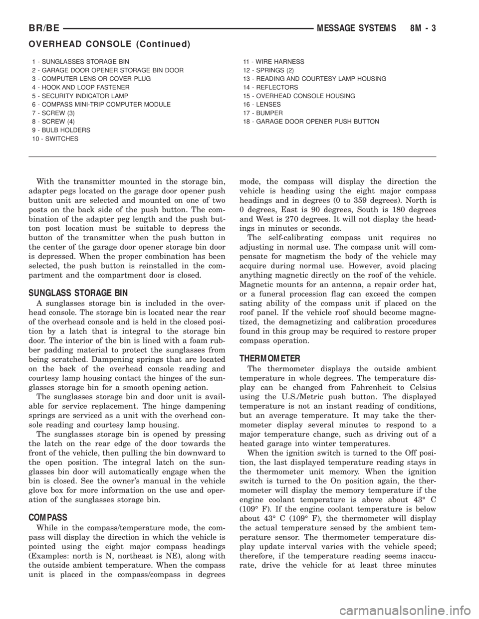
The premium overhead console (Fig. 1) includes
two front-mounted reading and courtesy lamps, a
garage door opener storage bin, and a sunglasses
storage bin. The premium overhead console includes
a compass mini-trip computer. The base overhead
console uses the same overhead console housing, but
has a computer cover plug installed in place of the
compass mini-trip computer display module lens and
push buttons.
The rear of the overhead console is secured to two
rear mounting holes in the inner roof panel by two
plastic hook formations that are integral to the over-
head console housing. The front of the overhead con-
sole is secured to the two front mounting holes of the
inner roof panel by two plastic latches that are inte-
gral to the overhead console housing. A single electri-
cal connection joins the overhead console wireharness to the roof wire harness for both the base
and premium overhead console units.
Following are general descriptions of the major
components used in the overhead console. See the
owner's manual in the vehicle glove box for more
information on the use and operation of the various
overhead console features.
GARAGE DOOR OPENER STORAGE BIN
A compartment near the front of the overhead con-
sole is designed to hold most garage door opener
remote control transmitters. The transmitter is
mounted within the compartment with an adhesive-
backed hook and loop fastener patch and, when the
compartment is closed, a push button in the center of
the compartment door is depressed to actuate the
transmitter.
A transmitter mounting kit including the adhesive-
backed hook and loop fastener material is available
for service. The garage door opener storage bin door
and the push button with three assorted length
adapter pegs are also available for service replace-
ment.
The garage door opener storage compartment door
is opened by pressing the integral latch towards the
front of the vehicle. When the compartment door is
opened, the push button unit is removed from the
compartment by squeezing the latch tabs and pulling
the unit downward. With the push button removed,
the garage door opener can be installed in the com-
partment using the adhesive-backed hook and loop
fastener material provided.
BR/BEMESSAGE SYSTEMS 8M - 1
Page 638 of 2889
With the transmitter mounted in the storage bin,
adapter pegs located on the garage door opener push
button unit are selected and mounted on one of two
posts on the back side of the push button. The com-
bination of the adapter peg length and the push but-
ton post location must be suitable to depress the
button of the transmitter when the push button in
the center of the garage door opener storage bin door
is depressed. When the proper combination has been
selected, the push button is reinstalled in the com-
partment and the compartment door is closed.
SUNGLASS STORAGE BIN
A sunglasses storage bin is included in the over-
head console. The storage bin is located near the rear
of the overhead console and is held in the closed posi-
tion by a latch that is integral to the storage bin
door. The interior of the bin is lined with a foam rub-
ber padding material to protect the sunglasses from
being scratched. Dampening springs that are located
on the back of the overhead console reading and
courtesy lamp housing contact the hinges of the sun-
glasses storage bin for a smooth opening action.
The sunglasses storage bin and door unit is avail-
able for service replacement. The hinge dampening
springs are serviced as a unit with the overhead con-
sole reading and courtesy lamp housing.
The sunglasses storage bin is opened by pressing
the latch on the rear edge of the door towards the
front of the vehicle, then pulling the bin downward to
the open position. The integral latch on the sun-
glasses bin door will automatically engage when the
bin is closed. See the owner's manual in the vehicle
glove box for more information on the use and oper-
ation of the sunglasses storage bin.
COMPASS
While in the compass/temperature mode, the com-
pass will display the direction in which the vehicle is
pointed using the eight major compass headings
(Examples: north is N, northeast is NE), along with
the outside ambient temperature. When the compass
unit is placed in the compass/compass in degreesmode, the compass will display the direction the
vehicle is heading using the eight major compass
headings and in degrees (0 to 359 degrees). North is
0 degrees, East is 90 degrees, South is 180 degrees
and West is 270 degrees. It will not display the head-
ings in minutes or seconds.
The self-calibrating compass unit requires no
adjusting in normal use. The compass unit will com-
pensate for magnetism the body of the vehicle may
acquire during normal use. However, avoid placing
anything magnetic directly on the roof of the vehicle.
Magnetic mounts for an antenna, a repair order hat,
or a funeral procession flag can exceed the compen
sating ability of the compass unit if placed on the
roof panel. If the vehicle roof should become magne-
tized, the demagnetizing and calibration procedures
found in this group may be required to restore proper
compass operation.
THERMOMETER
The thermometer displays the outside ambient
temperature in whole degrees. The temperature dis-
play can be changed from Fahrenheit to Celsius
using the U.S./Metric push button. The displayed
temperature is not an instant reading of conditions,
but an average temperature. It may take the ther-
mometer display several minutes to respond to a
major temperature change, such as driving out of a
heated garage into winter temperatures.
When the ignition switch is turned to the Off posi-
tion, the last displayed temperature reading stays in
the thermometer unit memory. When the ignition
switch is turned to the On position again, the ther-
mometer will display the memory temperature if the
engine coolant temperature is above about 43É C
(109É F). If the engine coolant temperature is below
about 43É C (109É F), the thermometer will display
the actual temperature sensed by the ambient tem-
perature sensor. The thermometer temperature dis-
play update interval varies with the vehicle speed;
therefore, if the temperature reading seems inaccu-
rate, drive the vehicle for at least three minutes
1 - SUNGLASSES STORAGE BIN
2 - GARAGE DOOR OPENER STORAGE BIN DOOR
3 - COMPUTER LENS OR COVER PLUG
4 - HOOK AND LOOP FASTENER
5 - SECURITY INDICATOR LAMP
6 - COMPASS MINI-TRIP COMPUTER MODULE
7 - SCREW (3)
8 - SCREW (4)
9 - BULB HOLDERS
10 - SWITCHES11 - WIRE HARNESS
12 - SPRINGS (2)
13 - READING AND COURTESY LAMP HOUSING
14 - REFLECTORS
15 - OVERHEAD CONSOLE HOUSING
16 - LENSES
17 - BUMPER
18 - GARAGE DOOR OPENER PUSH BUTTON
BR/BEMESSAGE SYSTEMS 8M - 3
OVERHEAD CONSOLE (Continued)
Page 639 of 2889
while maintaining a speed of 48 kilometers-per-hour
(30 miles-per-hour) or higher.
The thermometer function is supported by an
ambient temperature sensor. The sensor is mounted
outside the passenger compartment near the front
and center of the vehicle, and is hard wired to the
module. The ambient temperature sensor is available
as a separate service item.
STANDARD PROCEDURE - COMPASS
CALIBRATION
CAUTION: Do not place any external magnets, such
as magnetic roof mount antennas, in the vicinity of
the compass. Do not use magnetic tools when ser-
vicing the overhead console.
The electronic compass unit features a self-cali-
brating design, which simplifies the calibration pro-
cedure. This feature automatically updates the
compass calibration while the vehicle is being driven.
This allows the compass unit to compensate for small
changes in the residual magnetism that the vehicle
may acquire during normal use. If the compass read-
ings appear to be erratic or out of calibration, per-
form the following calibration procedure. Also, new
service replacement compass mini-trip computer
modules must have their compass calibrated using
this procedure. Do not attempt to calibrate the com-
pass near large metal objects such as other vehicles,
large buildings, or bridges; or, near overhead or
underground power lines.
(1) Start the engine. If the compass/temperature
data is not currently being displayed, momentarily
depress and release the Step push button to step
through the display options until you have reached
the compass/temperature display.
(2) Depress both the U.S./Metric and the Step
push buttons at the same time for more than six sec-
onds, until ªCALº appears in the display, then release
both push buttons. The ªCALº in the display indi-
cates that the compass is in the calibration mode.
(3) Drive the vehicle on a level surface, at least
fifty feet away from large metal objects and power
lines, in all four compass directions, such as driving
around a city block several times or driving in two to
three complete circles at a slow to medium speed.
(4) When the calibration is successfully completed,
ªCALº will disappear from the display and normal
compass mini-trip computer operation will resume.
NOTE: If the ªCALº message remains in the display,
either there is excessive magnetism near the com-
pass, or the unit is faulty. Repeat the calibration
procedure at least one more time.NOTE: If the wrong direction is still indicated in the
compass display, the area selected for calibration
may be too close to a strong magnetic field. Repeat
the calibration procedure in another location.
STANDARD PROCEDURE - COMPASS
VARIATION ADJUSTMENT
Compass variance, also known as magnetic decli-
nation, is the difference in angle between magnetic
north and true geographic north. In some geographic
locations, the difference between magnetic and geo-
graphic north is great enough to cause the compass
to give false readings. If this problem occurs, the
compass variance must be set. There are two meth-
ods that can be used to enter this information into
the compass mini-trip computer module. They are
the zone method and the direct method.
ZONE METHOD
(1) Using the Variance Settings map, find your
geographic location and note the zone number (Fig.
2).
(2) Turn the ignition switch to the On position. If
the compass/temperature data is not currently being
displayed, momentarily depress and release the Step
push button to step through the display options until
you have reached the compass/temperature display.
(3) Depress both the U.S./Metric and the Step
push buttons at the same time and hold them down
for more than 100 milliseconds, but not more than
one second. The compass mini-trip computer will
enter the variation adjustment mode and ªVARº
along with the current variance zone will appear in
the display.
(4) Momentarily depress and release the Step push
button to step through the zone numbers, until the
zone number for your geographic location appears in
the display.
(5) After five seconds, the displayed zone will auto-
matically be set in the compass mini-trip computer
module memory and normal operation will resume.
(6) Confirm that the correct directions are now
indicated by the compass.
DIRECT METHOD
(1) Turn the vehicle so it is headed in either the
north or south direction. The vehicle must be headed
within 45 degrees of north or south for this procedure
to work. The vehicle may be moving or stationary.
(2) Turn the ignition switch to the On position. If
the compass/temperature data is not currently being
displayed, momentarily depress and release the Step
push button to step through the display options until
you have reached the compass/temperature display.
8M - 4 MESSAGE SYSTEMSBR/BE
OVERHEAD CONSOLE (Continued)
Page 640 of 2889
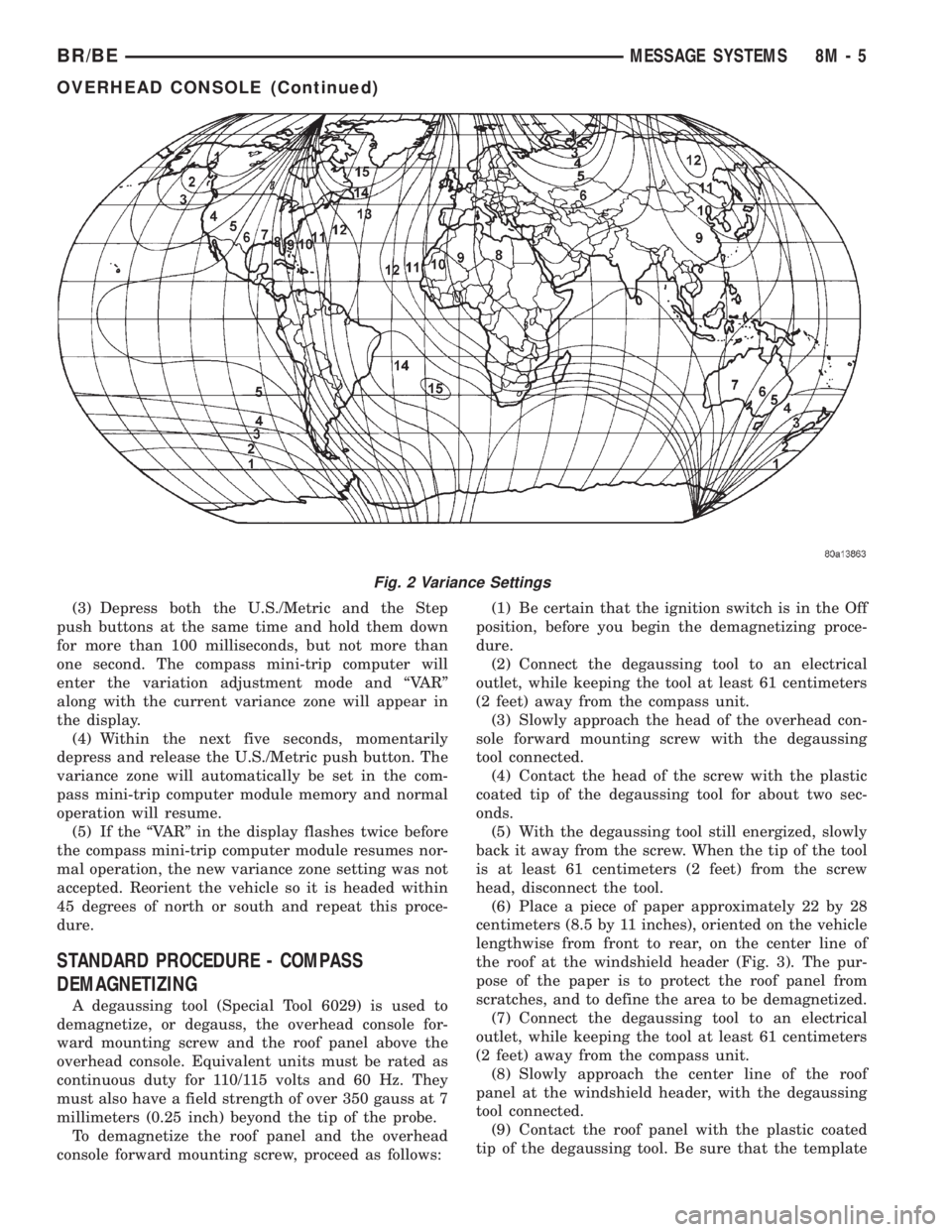
(3) Depress both the U.S./Metric and the Step
push buttons at the same time and hold them down
for more than 100 milliseconds, but not more than
one second. The compass mini-trip computer will
enter the variation adjustment mode and ªVARº
along with the current variance zone will appear in
the display.
(4) Within the next five seconds, momentarily
depress and release the U.S./Metric push button. The
variance zone will automatically be set in the com-
pass mini-trip computer module memory and normal
operation will resume.
(5) If the ªVARº in the display flashes twice before
the compass mini-trip computer module resumes nor-
mal operation, the new variance zone setting was not
accepted. Reorient the vehicle so it is headed within
45 degrees of north or south and repeat this proce-
dure.
STANDARD PROCEDURE - COMPASS
DEMAGNETIZING
A degaussing tool (Special Tool 6029) is used to
demagnetize, or degauss, the overhead console for-
ward mounting screw and the roof panel above the
overhead console. Equivalent units must be rated as
continuous duty for 110/115 volts and 60 Hz. They
must also have a field strength of over 350 gauss at 7
millimeters (0.25 inch) beyond the tip of the probe.
To demagnetize the roof panel and the overhead
console forward mounting screw, proceed as follows:(1) Be certain that the ignition switch is in the Off
position, before you begin the demagnetizing proce-
dure.
(2) Connect the degaussing tool to an electrical
outlet, while keeping the tool at least 61 centimeters
(2 feet) away from the compass unit.
(3) Slowly approach the head of the overhead con-
sole forward mounting screw with the degaussing
tool connected.
(4) Contact the head of the screw with the plastic
coated tip of the degaussing tool for about two sec-
onds.
(5) With the degaussing tool still energized, slowly
back it away from the screw. When the tip of the tool
is at least 61 centimeters (2 feet) from the screw
head, disconnect the tool.
(6) Place a piece of paper approximately 22 by 28
centimeters (8.5 by 11 inches), oriented on the vehicle
lengthwise from front to rear, on the center line of
the roof at the windshield header (Fig. 3). The pur-
pose of the paper is to protect the roof panel from
scratches, and to define the area to be demagnetized.
(7) Connect the degaussing tool to an electrical
outlet, while keeping the tool at least 61 centimeters
(2 feet) away from the compass unit.
(8) Slowly approach the center line of the roof
panel at the windshield header, with the degaussing
tool connected.
(9) Contact the roof panel with the plastic coated
tip of the degaussing tool. Be sure that the template
Fig. 2 Variance Settings
BR/BEMESSAGE SYSTEMS 8M - 5
OVERHEAD CONSOLE (Continued)
Page 642 of 2889
(7) Remove the overhead console from the vehicle.
OVERHEAD CONSOLE DISASSEMBLY
GARAGE DOOR OPENER STORAGE BIN REMOVAL
(1) Disconnect and isolate the battery negative
cable.
(2) Remove the overhead console from the head-
liner. Refer toOverhead Consolein the Removal
and Installation section of this group for the proce-
dures.
(3) If the vehicle is so equipped, remove the three
screws that secure the compass mini-trip computer
module to the back side of the overhead console hous-
ing. Move the module aside as needed for access to
the pivot latches that are integral to the overhead
console housing for the garage door opener storage
bin door pivot pins.
(4) Open the garage door opener storage bin door.
(5) From the back side of the of the overhead con-
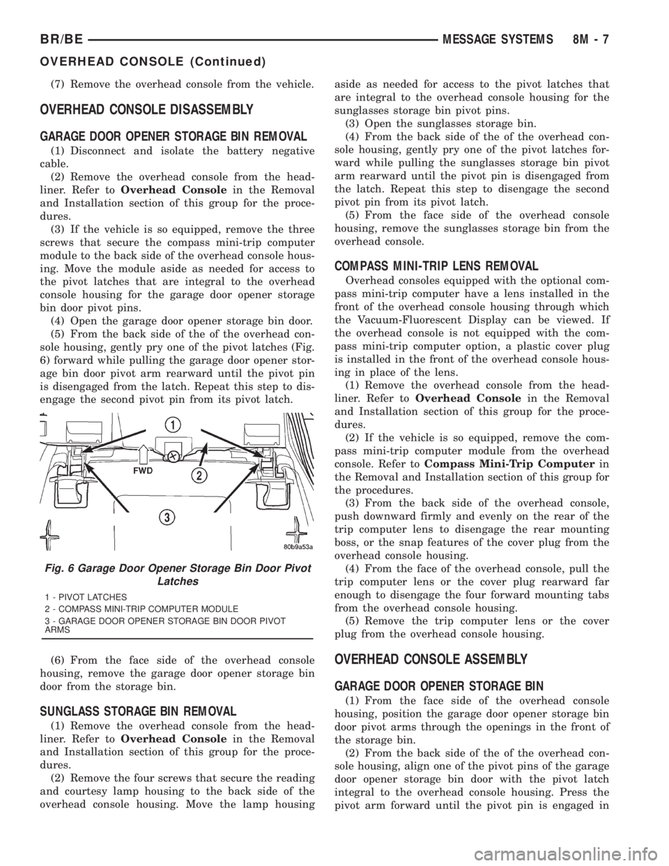
sole housing, gently pry one of the pivot latches (Fig.
6) forward while pulling the garage door opener stor-
age bin door pivot arm rearward until the pivot pin
is disengaged from the latch. Repeat this step to dis-
engage the second pivot pin from its pivot latch.
(6) From the face side of the overhead console
housing, remove the garage door opener storage bin
door from the storage bin.
SUNGLASS STORAGE BIN REMOVAL
(1) Remove the overhead console from the head-
liner. Refer toOverhead Consolein the Removal
and Installation section of this group for the proce-
dures.
(2) Remove the four screws that secure the reading
and courtesy lamp housing to the back side of the
overhead console housing. Move the lamp housingaside as needed for access to the pivot latches that
are integral to the overhead console housing for the
sunglasses storage bin pivot pins.
(3) Open the sunglasses storage bin.
(4) From the back side of the of the overhead con-
sole housing, gently pry one of the pivot latches for-
ward while pulling the sunglasses storage bin pivot
arm rearward until the pivot pin is disengaged from
the latch. Repeat this step to disengage the second
pivot pin from its pivot latch.
(5) From the face side of the overhead console
housing, remove the sunglasses storage bin from the
overhead console.
COMPASS MINI-TRIP LENS REMOVAL
Overhead consoles equipped with the optional com-
pass mini-trip computer have a lens installed in the
front of the overhead console housing through which
the Vacuum-Fluorescent Display can be viewed. If
the overhead console is not equipped with the com-
pass mini-trip computer option, a plastic cover plug
is installed in the front of the overhead console hous-
ing in place of the lens.
(1) Remove the overhead console from the head-
liner. Refer toOverhead Consolein the Removal
and Installation section of this group for the proce-
dures.
(2) If the vehicle is so equipped, remove the com-
pass mini-trip computer module from the overhead
console. Refer toCompass Mini-Trip Computerin
the Removal and Installation section of this group for
the procedures.
(3) From the back side of the overhead console,
push downward firmly and evenly on the rear of the
trip computer lens to disengage the rear mounting
boss, or the snap features of the cover plug from the
overhead console housing.
(4) From the face of the overhead console, pull the
trip computer lens or the cover plug rearward far
enough to disengage the four forward mounting tabs
from the overhead console housing.
(5) Remove the trip computer lens or the cover
plug from the overhead console housing.
OVERHEAD CONSOLE ASSEMBLY
GARAGE DOOR OPENER STORAGE BIN
(1) From the face side of the overhead console
housing, position the garage door opener storage bin
door pivot arms through the openings in the front of
the storage bin.
(2) From the back side of the of the overhead con-
sole housing, align one of the pivot pins of the garage
door opener storage bin door with the pivot latch
integral to the overhead console housing. Press the
pivot arm forward until the pivot pin is engaged in
Fig. 6 Garage Door Opener Storage Bin Door Pivot
Latches
1 - PIVOT LATCHES
2 - COMPASS MINI-TRIP COMPUTER MODULE
3 - GARAGE DOOR OPENER STORAGE BIN DOOR PIVOT
ARMS
BR/BEMESSAGE SYSTEMS 8M - 7
OVERHEAD CONSOLE (Continued)
Page 643 of 2889
the latch. Repeat this step to engage the second pivot
pin with its pivot latch.
(3) Close the garage door opener storage bin door.
(4) If the vehicle is so equipped, position the com-
pass mini-trip computer module to the back side of
the overhead console housing. Install and tighten the
three screws that secure the module to the housing.
Tighten the screws to 2.2 N´m (20 in. lbs.).
(5) Install the overhead console onto the headliner.
Refer toOverhead Consolein the Removal and
Installation section of this group for the procedures.
SUNGLASS STORAGE BIN
(1) From the face side of the overhead console
housing, position the sunglasses storage bin pivot
arms through the openings in the front of the storage
bin housing in the overhead console.
(2) From the back side of the of the overhead con-
sole housing, align one of the pivot pins of the sun-
glasses storage bin with the pivot latch integral to
the overhead console housing. Press the pivot arm
forward until the pivot pin is engaged in the latch.
Repeat this step to engage the second pivot pin with
its pivot latch.
(3) Close the sunglasses storage bin.
(4) Position the reading and courtesy lamp housing
to the back side of the overhead console housing.
Install and tighten the four screws that secure the
lamp housing to the back of the overhead console
housing. Tighten the screws to 2.2 N´m (20 in. lbs.).
(5) Install the overhead console onto the headliner.
Refer toOverhead Consolein the Removal and
Installation section of this group for the procedures.
MINI-TRIP COMPUTER LENS
Overhead consoles equipped with the optional com-
pass mini-trip computer have a lens installed in the
front of the overhead console housing through which
the Vacuum-Fluorescent Display can be viewed. If
the overhead console is not equipped with the com-
pass mini-trip computer option, a plastic cover plug
is installed in the front of the overhead console hous-
ing in place of the lens.
(1) Remove the trip computer lens or the cover
plug onto the overhead console housing.
(2) From the face of the overhead console, push the
trip computer lens or the cover plug forward far
enough to engage the four forward mounting tabs in
the overhead console unit.
(3) From the face of the overhead console, align
the rear mounting boss of the trip computer lens or
the alignment pin of the cover plug with the recepta-
cle in the overhead console housing.
(4) Press firmly and evenly on the rear edge of the
trip computer lens or the cover plug until the rear
mounting boss is fully seated in the receptacle, or thesnap features of the cover plug are fully engaged in
the overhead console housing.
(5) If the vehicle is so equipped, install the com-
pass mini-trip computer module onto the overhead
console. Refer toCompass Mini-Trip Computerin
the Removal and Installation section of this group for
the procedures.
(6) Install the overhead console onto the headliner.
Refer toOverhead Consolein the Removal and
Installation section of this group for the procedures.
INSTALLATION
(1) Position the overhead console near the mount-
ing location on the headliner in the vehicle.
(2) Reconnect the roof wire harness connector to
the overhead console wire harness connector.
(3) Engage the two mounting hooks on the rear of
the overhead console housing in the mounting holes
in the inner roof panel.
(4) Slide the overhead console forward far enough
to align the two latches on the front of the housing
with their receptacles in the inner roof panel.
(5) Push upward firmly and evenly on the front of
the overhead console until each of the two latches is
fully engaged in its receptacle in the inner roof panel.
(6) Close the garage door opener storage bin door.
(7) Reconnect the battery negative cable.
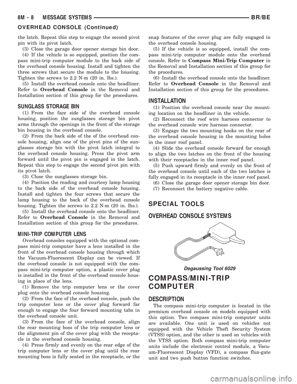
SPECIAL TOOLS
OVERHEAD CONSOLE SYSTEMS
COMPASS/MINI-TRIP
COMPUTER
DESCRIPTION
The compass mini-trip computer is located in the
premium overhead console on models equipped with
this option. Two compass mini-trip computer units
are available. One unit is used on vehicles not
equipped with the Vehicle Theft Security System
(VTSS) option, and the other is used on vehicles with
the VTSS option. Both compass mini-trip computer
units include the electronic control module, a Vacu-
um-Fluorescent Display (VFD), a compass flux-gate
unit and two push button function switches.
Degaussing Tool 6029
8M - 8 MESSAGE SYSTEMSBR/BE
OVERHEAD CONSOLE (Continued)
Page 644 of 2889
Compass mini-trip computer units for vehicles
equipped with the VTSS include a red Light-Emit-
ting Diode (LED) on their electronic circuit board.
This LED protrudes through the bottom of the lens
on the front of the overhead console unit, and serves
as the security indicator lamp. Refer toSecurity
Indicator Lampin Vehicle Theft/Security Systems
for more information on this feature.
The compass mini-trip computer module contains a
central processing unit and interfaces with other
electronic modules in the vehicle on the Chrysler Col-
lision Detection (CCD) data bus network. The CCD
data bus network allows the sharing of sensor infor-
mation. This helps to reduce wire harness complexity,
reduce internal controller hardware, and reduce com-
ponent sensor current loads. At the same time, this
system provides increased reliability, enhanced diag-
nostics, and allows the addition of many new feature
capabilities.
The compass mini-trip computer provides several
electronic functions and features. Some of the func-
tions and features that the compass mini-trip com-
puter module supports and/or controls, include the
following display options:
²Compass and temperature- provides the out-
side temperature and one of eight compass readings
to indicate the direction the vehicle is facing.
²Compass and compass in degrees- provides
one of eight compass readings to indicate the direc-
tion the vehicle is facing and provides the compass
direction in degrees.
²Trip odometer (ODO)- shows the distance
travelled since the last trip computer reset.
²Average fuel economy (AVG ECO)- shows
the average fuel economy since the last trip computer
reset.
²Instant fuel economy (ECO)- shows the
present fuel economy based upon the current vehicle
distance and fuel used information.
²Distance to empty (DTE)- shows the esti-
mated distance that can be travelled with the fuel
remaining in the fuel tank. This estimated distance
is computed using the average miles-per-gallon from
the last 30 gallons of fuel used.
²Elapsed time (ET)- shows the accumulated
ignition-on time since the last trip computer reset.
²Blank screen- the compass mini-trip VFD is
turned off.
The ambient temperature sensor is hard wired to
the compass mini-trip computer module. Data input
for all other compass mini-trip computer functions,
including VFD dimming level, is received through
CCD data bus messages. The compass mini-trip com-
puter uses its internal programming and all of these
inputs to calculate and display the requested data. If
the data displayed is incorrect, perform the self-diag-nostic tests as described in this group. If these tests
prove inconclusive, the use of a DRBIIItscan tool
and the proper Diagnostic Procedures manual are
recommended for further testing of the compass
mini-trip computer module and the CCD data bus.
The compass mini-trip computer module cannot be
repaired, and is available for service only as a unit. If
faulty or damaged, the complete module must be
replaced.
OPERATION
The compass mini-trip computer only operates with
the ignition switch in the On position. When the igni-
tion switch is turned to the On position, all of the
segments in the compass mini-trip computer VFD
will be turned on for one second, then the display
will return to the last function being displayed before
the ignition was turned to the Off position. With the
ignition switch in the On position, momentarily
depressing and releasing the Step push button switch
will cause the compass-mini-trip computer to change
its mode of operation, and momentarily depressing
and releasing the U.S./Metric push button will cause
the unit to toggle between U.S. and Metric measure-
ments. While in either compass mode, depressing the
U.S./Metric push button for more than ten seconds
will toggle the display between the compass/temper-
ature and the compass/compass in degrees modes.
This compass mini-trip computer features several
functions that can be reset. If both the Step and U.S./
Metric push buttons are depressed at the same time
with the ignition switch in the On position, the trip
computer information that can be reset is reset.
Depressing and releasing the Step and U.S./Metric
push buttons at the same time for more than 100
milliseconds, but not more than one second while in
any display mode (except the compass/temperature
mode) will cause a local reset. A local reset affects
only the function currently displayed. See the Reset
Chart below for more information on this feature.
Performing a local reset while in the compass/tem-
perature mode enters the module into the compass
variance setting mode.
Depressing and releasing the Step and U.S./Metric
push buttons at the same time for more than two
seconds while in any display mode (except the com-
pass/temperature mode) will cause a global reset. A
global reset changes all of the trip computer func-
tions that can be reset.
For more information on the features and control
functions of the compass mini-trip computer, see the
owner's manual in the vehicle glove box.
BR/BEMESSAGE SYSTEMS 8M - 9
COMPASS/MINI-TRIP COMPUTER (Continued)
Page 645 of 2889
DIAGNOSIS & TESTING - COMPASS MINI-TRIP
COMPUTER
If the problem with the compass mini-trip com-
puter module is an inoperative security indicator
lamp, refer toSecurity Indicator Lampin Vehicle
Theft/Security Systems. If the problem with the com-
pass mini-trip computer module is an ªOCº or ªSCº in
the compass/thermometer display, refer toAmbient
Temperature Sensorin the Diagnosis and Testing
section of this group. If the problem with the com-
pass mini-trip computer module is an inaccurate or
scrambled display, refer toSelf-Diagnostic Testin
the Diagnosis and Testing section of this group. If the
problem with the compass mini-trip computer module
is incorrect Vacuum Fluorescent Display (VFD) dim-
ming levels, use a DRBtscan tool and the proper
Diagnostic Procedures manual to test for the correct
dimming message inputs being received from the
instrument cluster over the Chrysler Collision Detec-
tion (CCD) data bus. If the problem is a no-display
condition, use the following procedures. For complete
circuit diagrams, refer toOverhead Consolein the
Contents of Wiring Diagrams.
(1) Check the fused B(+) fuse in the junction block.
If OK, go to Step 2. If not OK, repair the shorted cir-
cuit or component as required and replace the faulty
fuse.
(2) Check for battery voltage at the fused B(+) fuse
in the junction block. If OK, go to Step 3. If not OK,
repair the open fused B(+) circuit to the battery as
required.
(3) Check the fused ignition switch output (run/
start) fuse in the junction block. If OK, go to Step 4.
If not OK, repair the shorted circuit or component as
required and replace the faulty fuse.
(4) Turn the ignition switch to the On position.
Check for battery voltage at the fused ignition switch
output (run/start) fuse in the junction block. If OK,
go to Step 5. If not OK, repair the open fused ignition
switch output (run/start) circuit to the ignition switch
as required.
(5) Turn the ignition switch to the Off position.
Disconnect and isolate the battery negative cable.
Remove the overhead console. Check for continuity
between the ground circuit cavities of the roof wire
harness connector for the overhead console and a
good ground. There should be continuity. If OK, go to
Step 6. If not OK, repair the open ground circuit to
ground as required.
(6) Connect the battery negative cable. Check for
battery voltage at the fused B(+) circuit cavity of the
roof wire harness connector for the overhead console.
If OK, go to Step 7. If not OK, repair the open fused
B(+) circuit to the junction block fuse as required.(7) Turn the ignition switch to the On position.
Check for battery voltage at the fused ignition switch
output (run/start) circuit cavity of the roof wire har-
ness connector for the overhead console. If OK, refer
toSelf-Diagnostic Testin the Diagnosis and Test-
ing section of this group for further diagnosis of the
compass mini-trip computer module and the CCD
data bus. If not OK, repair the open fused ignition
switch output (run/start) circuit to the junction block
fuse as required.
SELF-DIAGNOSTIC TEST
A self-diagnostic test is used to determine that the
compass mini-trip computer module is operating
properly electrically. Initiate the self-diagnostic test
as follows:
(1) With the ignition switch in the Off position,
simultaneously depress and hold the Step button and
the U.S./Metric button.
(2) Turn the ignition switch to the On position.
(3) Continue to hold both buttons depressed until
the compass mini-trip computer module enters the
display segment test. In this test, all of the Vacuum
Fluorescent Display (VFD) segments are lighted
while the compass mini-trip computer module per-
forms the following checks:
²Microprocessor RAM read/write test
²Non-volatile memory read/write test
²Microprocessor ROM verification test
²CCD communications test.
(4) Following completion of these tests, the com-
pass mini-trip computer will display one of three
messages: ªPASS,º ªFAIL,º or ªCCd.º Respond to the
respective test results as follows:
²If the ªPASSº message is displayed, but compass
mini-trip computer operation is still improper, the
use of a DRB scan tool and the proper Diagnostic
Procedures manual are required for further diagno-
sis.
²If the ªFAILº message is displayed, the compass
mini-trip computer module is faulty and must be
replaced.
²If the ªCCdº message is displayed, the use of a
DRBtscan tool and the proper Diagnostic Proce-
dures manual are required for further diagnosis.
²If any VFD segment should fail to light during
the display segment test, the compass mini-trip com-
puter module is faulty and must be replaced.
(5) If all tests are passed, or if the ignition switch
is turned to the Off position, the compass mini-trip
computer module will automatically return to normal
operation.
8M - 10 MESSAGE SYSTEMSBR/BE
COMPASS/MINI-TRIP COMPUTER (Continued)