fuel filter location DODGE RAM 2001 Service Repair Manual
[x] Cancel search | Manufacturer: DODGE, Model Year: 2001, Model line: RAM, Model: DODGE RAM 2001Pages: 2889, PDF Size: 68.07 MB
Page 20 of 2889
MAINTENANCE SCHEDULES
LIGHT DUTY ENGINE (1500 AND 2500
MODELS EXCEPT 8.0L) MAINTENANCE
SCHEDULES
There are two maintenance schedules that show
proper service for the vehicle.
First is ScheduleªAº. It lists all the scheduled
maintenance to be performed under ªnormalº operat-
ing conditions.
Second is ScheduleªBºIt is a schedule for vehicles
that are operated under the conditions listed at the
beginning of that schedule.
Use the schedule that best describes the driving
conditions.
Where time and mileage are listed, follow the
interval that occurs first.
At Each Stop For Fuel
²Check engine oil level and add as required.
²Check windshield washer solvent and add as
required.
²Clean windshield and wiper blades as required.
Once A Month
²Check tire pressure and look for unusual wear
or damage.
²Inspect battery and clean and tighten terminals
as required.
²Check fluid levels of coolant reservoir, brake
master cylinder, power steering, and transmission
and add as needed.
²Check all lights and all other electrical items for
correct operation.
²Inspect and clean wiper blades. Replace if
required.
At Each Oil Change
²Inspect exhaust system.
²Inspect brake hoses.
²Adjust rear brake shoe to drum clearance.
²Rotate the tires at each oil change interval
shown on schedule ªAº (7,500 Miles) or every other
interval shown on schedule ªBº (6,000 Miles).
²Check engine coolant level, hoses, and clamps.
²Lubricate steering linkage.
EMISSION CONTROL SYSTEM MAINTENANCE
The scheduled emission maintenance listed inbold
typeon the Maintenance Schedules, must be done at
the mileage specified to assure the continued proper
functioning of the emission control system. These,
and all other maintenance services included in this
manual, should be done to provide the best vehicle
performance and reliability. More frequent mainte-
nance may be needed for vehicles in severe operatingconditions such as dusty areas and very short trip
driving.
FLUID FILL LOCATIONS AND LUBRICATION
POINTS
The fluid check/fill locations and lubrication points
are located in each applicable group.
LIGHT DUTY SCHEDULE ªAº
7,500 Miles (12 000 km) or at 6 months
²Change engine oil.
²Replace engine oil filter.
²Inspect engine coolant level, hoses, and clamps.
²Inspect brake hoses.
²Lubricate the steering linkages.
²Check manual transmission fluid level.
²Inspect exhaust system.
15,000 Miles (24 000 km) or at 12 months
²Change engine oil.
²Replace engine oil filter.
²Inspect engine coolant level, hoses, and clamps.
²Inspect brake hoses.
²Lubricate the steering linkages.
²Check manual transmission fluid level.
²Inspect exhaust system.
22,500 Miles (36 000 km) or at 18 months
²Change engine oil.
²Replace engine oil filter.
²Inspect engine coolant level, hoses, and clamps.
²Inspect brake hoses.
²Inspect brake linings.
²Inspect front wheel bearings. Clean and repack,
if required (4x2).
²Lubricate the steering linkages.
²Lubricate non permanently sealed ball joints.
²Check manual transmission fluid level.
²Inspect exhaust system.
30,000 Miles (48 000 km) or at 24 months
²Replace engine air cleaner element.
²Replace spark plugs.
²Change engine oil.
²Replace engine oil filter.
²Inspect engine coolant level, hoses, and clamps.
²Inspect brake hoses.
²Lubricate the steering linkages.
²Inspect manual transmission fluid level.
²Inspect exhaust system.
37,500 Miles (60 000 km) or at 30 months
²Change engine oil.
²Replace engine oil filter.
²Inspect engine coolant level, hoses, and clamps.
BR/BELUBRICATION & MAINTENANCE 0 - 7
Page 30 of 2889
²Inspect brake linings.
³Off-the-highway operation, trailer towing snow
plowing, prolonged operation with heavy loading,
especially in hot weather require the more frequent
transmission service indicated with an ³ in Schedule
ªBº. Perform these services if the vehicle is usually
operated under these conditions.
Inspection and service should also be performed
anytime a malfunction is observed or suspected.
DESCRIPTION - HEAVY DUTY ENGINE
(FEDERAL ONLY ± 2500 8.0L HD AND 3500
5.9L& 8.0L MODELS) MAINTENANCE
SCHEDULES
There are two maintenance schedules that show
proper service based on the conditions that the vehi-
cle is subjected to. Use the schedule that best
describes these conditions.
ScheduleªAº, lists all the scheduled maintenance
to be performed under normal operating conditions
for Heavy Duty vehicles.
ScheduleªBº, lists maintenance recommended for
Heavy Duty vehicles operated under the conditions
listed at the beginning of that schedule.
²Where time and mileage are listed, follow the
interval that occurs first.
At Each Stop For Fuel
²Check engine oil level, add as required.
²Check windshield washer solvent and add if
required.
²Clean windshield and wiper blades as required.
Once A Month
²Check tire pressure and look for unusual wear
or damage.
²Inspect battery and clean and tighten terminals
as required.
²Check fluid levels of coolant reservoir, power
steering and transmission and add as needed.
²Check all lights and all other electrical items for
correct operation.
²Inspect and clean wiper blades. Replace if
required.
At Each Oil Change
²Inspect exhaust system.
²Inspect brake hoses.
²Adjust rear brakes.
²Rotate the tires at each oil change interval
shown on schedule ªAº (6,000 Miles) or every other
interval shown on schedule ªBº (6,000 Miles).
²Check engine coolant level, hoses, and clamps.
²Lubricate steering linkage.
EMISSION CONTROL SYSTEM MAINTENANCE
The scheduled emission maintenance listed inbold
typeon the Maintenance Schedules, must be done at
the mileage specified to assure the continued proper
functioning of the emission control system. These,
and all other maintenance services included in this
manual, should be done to provide the best vehicle
performance and reliability. More frequent mainte-
nance may be needed for vehicles in severe operating
conditions such as dusty areas and very short trip
driving.
FLUID FILL LOCATIONS AND LUBRICATION
POINTS
The fluid fill/check locations and lubrication points
are located in each applicable group.
HEAVY DUTY SCHEDULE ªAº
6,000 miles (10 000 km) or at 6 months
²Change engine oil.
²Replace engine oil filter.
12,000 Miles (19 000 km) or at 12 months
²Change engine oil.
²Replace engine oil filter.
²Inspect engine air cleaner element, replace
as necessary (8.0L only).
18,000 Miles (29 000 km) or at 18 months
²Change engine oil.
²Replace engine oil filter.
²Inspect brake linings
²Inspect front wheel bearings. Clean and repack,
if required (4x4).
24,000 Miles (38 000 km) or at 24 months
²Change engine oil.
²Replace engine oil filter.
²Replace engine air cleaner element and air
pump filter.
²Clean and lubricate crankcase inlet air filter
(5.9L).
²Drain and refill automatic transmission fluid.
Replace filter and adjust bands.
²Inspect front wheel bearings. Clean and repack,
if required (4x2).
30,000 Miles (48 000 km) or at 30 months
²Change engine oil.
²Replace engine oil filter.
²Replace spark plugs.
36,000 Miles (58 000 km) or at 36 months
²Change engine oil.
²Replace engine oil filter.
BR/BELUBRICATION & MAINTENANCE 0 - 17
MAINTENANCE SCHEDULES (Continued)
Page 36 of 2889
FLUID FILL LOCATIONS AND LUBRICATION
POINTS
The fluid fill/check locations and lubrication points
are located in each applicable group.
SCHEDULE ªAº
7,500 Miles (12 000 km) or at 6 months
²Change engine oil and filter.
²Drain crankcase breather canister (if equipped).
15,000 Miles (24 000 km) or at 12 months
²Change engine oil and filter.
²Drain crankcase breather canister (if equipped).
²Inspect water pump weep hole for blockage.
²Replace fuel filter and clean water in fuel sen-
sor.
22,500 Miles (36 000 km) or at 18 months
²Change engine oil and filter.
²Drain crankcase breather canister (if equipped).
²Inspect drive belts, replace as necessary.
²Inspect brake linings.
30,000 Miles (48 000 km) or at 24 months
²Change engine oil and filter.
²Drain crankcase breather canister (if equipped).
²Inspect fan hub.
²Inspect damper.
²Inspect water pump weep hole for blockage.
²Replace fuel filter and clean water in fuel sen-
sor.
²Drain and refill automatic transmission fluid.
Replace filter and adjust bands.
²Inspect front wheel bearings. Clean and repack,
if required (4x2).
²Flush and replace engine coolant if not done at
36 months.
37,500 Miles (60 000 km) or at 30 months
²Change engine oil and filter.
²Drain crankcase breather canister (if equipped).
45,000 Miles (72 000 km) or at 36 months
²Change engine oil and filter.
²Drain crankcase breather canister (if equipped).
²Inspect drive belts, replace as necessary.
²Inspect water pump weep hole for blockage.
²Replace fuel filter and clean water in fuel sen-
sor.
²Drain and refill transfer case fluid.
²Inspect brake linings.
²Flush and replace engine coolant if not done at
24 months
52,500 Miles (84 000 km) or at 42 months
²Change engine oil and filter.
²Drain crankcase breather canister (if equipped).
60,000 Miles (96 000 km) or at 48 months
²Change engine oil and filter.
²Drain crankcase breather canister (if equipped).
²Drain and refill automatic transmission fluid.
Replace filter and adjust bands.
²Inspect fan hub.
²Inspect damper.
²Inspect front wheel bearings. Clean and repack,
if required (4x2).
²Inspect water pump weep hole for blockage.
²Replace fuel filter and clean water in fuel sen-
sor.
67,500 Miles (108 000 km) or at 54 months
²Change engine oil and filter.
²Drain crankcase breather canister (if equipped).
²Inspect drive belts, replace as necessary.
²Inspect brake linings.
75,000 Miles (120 000 km) or at 60 months
²Change engine oil and filter.
²Drain crankcase breather canister (if equipped).
²Inspect water pump weep hole for blockage.
²Replace fuel filter and clean water in fuel sen-
sor.
²Flush and replace engine coolant if it has been
30,000 miles (48 000 km) or 24 months since last
change.
82,500 Miles (132 000 km) or at 66 months
²Change engine oil and filter.
²Drain crankcase breather canister (if equipped).
90,000 Miles (144 000 km) or at 72 months
²Change engine oil and filter.
²Drain crankcase breather canister (if equipped).
²Inspect drive belt, replace as required.
²Drain and refill automatic transmission fluid.
Replace filter and adjust bands.
²Drain and refill transfer case fluid.
²Inspect fan hub.
²Inspect damper.
²Inspect water pump weep hole for blockage.
²Replace fuel filter and clean water in fuel sen-
sor.
²Inspect front wheel bearings. Clean and repack,
if required (4x2).
²Inspect brake linings.
97,500 Miles (156 000 km) or at 78 months
²Change engine oil and filter.
²Drain crankcase breather canister (if equipped).
BR/BELUBRICATION & MAINTENANCE 0 - 23
MAINTENANCE SCHEDULES (Continued)
Page 464 of 2889
ENGINE CONTROL MODULE
DESCRIPTION - ECM
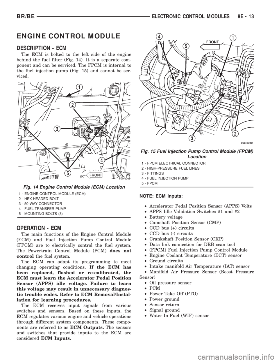
The ECM is bolted to the left side of the engine
behind the fuel filter (Fig. 14). It is a separate com-
ponent and can be serviced. The FPCM is internal to
the fuel injection pump (Fig. 15) and cannot be ser-
viced.
OPERATION - ECM
The main functions of the Engine Control Module
(ECM) and Fuel Injection Pump Control Module
(FPCM) are to electrically control the fuel system.
The Powertrain Control Module (PCM)does not
controlthe fuel system.
The ECM can adapt its programming to meet
changing operating conditions.If the ECM has
been replaced, flashed or re-calibrated, the
ECM must learn the Accelerator Pedal Position
Sensor (APPS) idle voltage. Failure to learn
this voltage may result in unnecessary diagnos-
tic trouble codes. Refer to ECM Removal/Instal-
lation for learning procedures.
The ECM receives input signals from various
switches and sensors. Based on these inputs, the
ECM regulates various engine and vehicle operations
through different system components. These compo-
nents are referred to asECM Outputs.The sensors
and switches that provide inputs to the ECM are
consideredECM Inputs.NOTE: ECM Inputs:
²Accelerator Pedal Position Sensor (APPS) Volts
²APPS Idle Validation Switches #1 and #2
²Battery voltage
²Camshaft Position Sensor (CMP)
²CCD bus (+) circuits
²CCD bus (-) circuits
²Crankshaft Position Sensor (CKP)
²Data link connection for DRB scan tool
²(FPCM) Fuel Injection Pump Control Module
²Engine Coolant Temperature (ECT) sensor
²Ground circuits
²Intake manifold Air Temperature (IAT) sensor
²Manifold Air Pressure Sensor (Boost Pressure
Sensor)
²Oil pressure sensor
²PCM
²Power Take Off (PTO)
²Power ground
²Sensor return
²Signal ground
²Water-In-Fuel (WIF) sensor
Fig. 14 Engine Control Module (ECM) Location
1 - ENGINE CONTROL MODULE (ECM)
2 - HEX HEADED BOLT
3 - 50-WAY CONNECTOR
4 - FUEL TRANSFER PUMP
5 - MOUNTING BOLTS (3)
Fig. 15 Fuel Injection Pump Control Module (FPCM)
Location
1 - FPCM ELECTRICAL CONNECTOR
2 - HIGH-PRESSURE FUEL LINES
3 - FITTINGS
4 - FUEL INJECTION PUMP
5 - FPCM
BR/BEELECTRONIC CONTROL MODULES 8E - 13
Page 465 of 2889
NOTE: ECM Outputs:
After inputs are received by the ECM, certain sen-
sors, switches and components are controlled or reg-
ulated by the ECM. These are consideredECM
Outputs.These outputs are for:
²CCD bus (+) circuits
²CCD bus (-) circuits
²CKP and APPS outputs to the PCM
²Data link connection for DRB scan tool
²Five volt sensor supply
²Fuel injection pump
²Fuel injection pump relay
²(FPCM) Fuel Pump Control Module
²Fuel transfer (lift) pump
²Intake manifold air heater relays #1 and #2 con-
trol circuits
²Malfunction indicator lamp (Check engine lamp)
²Oil pressure gauge/warning lamp
²PCM
²Wait-to-start warning lamp
²Water-In-Fuel (WIF) warning lamp
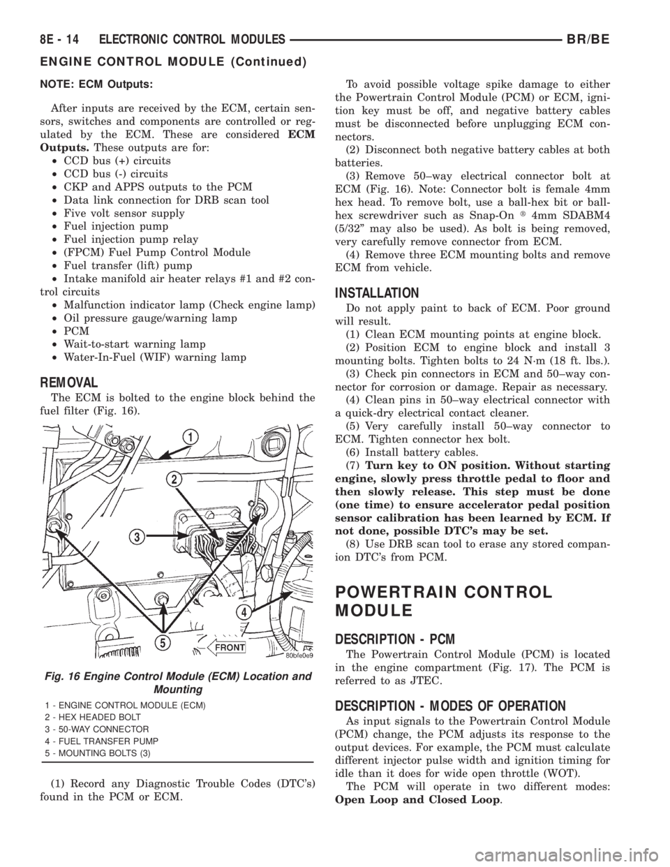
REMOVAL
The ECM is bolted to the engine block behind the
fuel filter (Fig. 16).
(1) Record any Diagnostic Trouble Codes (DTC's)
found in the PCM or ECM.To avoid possible voltage spike damage to either
the Powertrain Control Module (PCM) or ECM, igni-
tion key must be off, and negative battery cables
must be disconnected before unplugging ECM con-
nectors.
(2) Disconnect both negative battery cables at both
batteries.
(3) Remove 50±way electrical connector bolt at
ECM (Fig. 16). Note: Connector bolt is female 4mm
hex head. To remove bolt, use a ball-hex bit or ball-
hex screwdriver such as Snap-Ont4mm SDABM4
(5/32º may also be used). As bolt is being removed,
very carefully remove connector from ECM.
(4) Remove three ECM mounting bolts and remove
ECM from vehicle.
INSTALLATION
Do not apply paint to back of ECM. Poor ground
will result.
(1) Clean ECM mounting points at engine block.
(2) Position ECM to engine block and install 3
mounting bolts. Tighten bolts to 24 N´m (18 ft. lbs.).
(3) Check pin connectors in ECM and 50±way con-
nector for corrosion or damage. Repair as necessary.
(4) Clean pins in 50±way electrical connector with
a quick-dry electrical contact cleaner.
(5) Very carefully install 50±way connector to
ECM. Tighten connector hex bolt.
(6) Install battery cables.
(7)Turn key to ON position. Without starting
engine, slowly press throttle pedal to floor and
then slowly release. This step must be done
(one time) to ensure accelerator pedal position
sensor calibration has been learned by ECM. If
not done, possible DTC's may be set.
(8) Use DRB scan tool to erase any stored compan-
ion DTC's from PCM.
POWERTRAIN CONTROL
MODULE
DESCRIPTION - PCM
The Powertrain Control Module (PCM) is located
in the engine compartment (Fig. 17). The PCM is
referred to as JTEC.
DESCRIPTION - MODES OF OPERATION
As input signals to the Powertrain Control Module
(PCM) change, the PCM adjusts its response to the
output devices. For example, the PCM must calculate
different injector pulse width and ignition timing for
idle than it does for wide open throttle (WOT).
The PCM will operate in two different modes:
Open Loop and Closed Loop.
Fig. 16 Engine Control Module (ECM) Location and
Mounting
1 - ENGINE CONTROL MODULE (ECM)
2 - HEX HEADED BOLT
3 - 50-WAY CONNECTOR
4 - FUEL TRANSFER PUMP
5 - MOUNTING BOLTS (3)
8E - 14 ELECTRONIC CONTROL MODULESBR/BE
ENGINE CONTROL MODULE (Continued)
Page 1094 of 2889
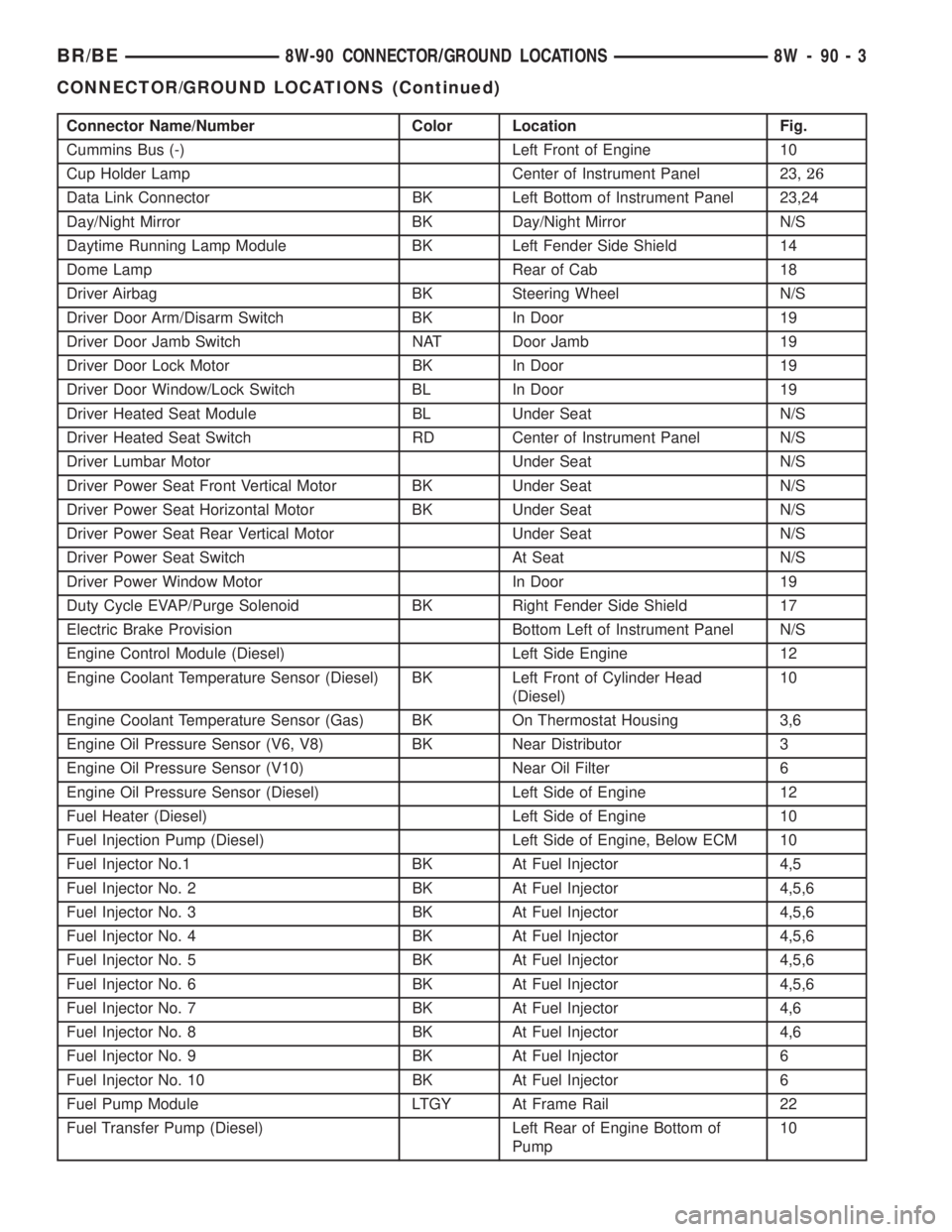
Connector Name/Number Color Location Fig.
Cummins Bus (-) Left Front of Engine 10
Cup Holder Lamp Center of Instrument Panel 23,26
Data Link Connector BK Left Bottom of Instrument Panel 23,24
Day/Night Mirror BK Day/Night Mirror N/S
Daytime Running Lamp Module BK Left Fender Side Shield 14
Dome Lamp Rear of Cab 18
Driver Airbag BK Steering Wheel N/S
Driver Door Arm/Disarm Switch BK In Door 19
Driver Door Jamb Switch NAT Door Jamb 19
Driver Door Lock Motor BK In Door 19
Driver Door Window/Lock Switch BL In Door 19
Driver Heated Seat Module BL Under Seat N/S
Driver Heated Seat Switch RD Center of Instrument Panel N/S
Driver Lumbar Motor Under Seat N/S
Driver Power Seat Front Vertical Motor BK Under Seat N/S
Driver Power Seat Horizontal Motor BK Under Seat N/S
Driver Power Seat Rear Vertical Motor Under Seat N/S
Driver Power Seat Switch At Seat N/S
Driver Power Window Motor In Door 19
Duty Cycle EVAP/Purge Solenoid BK Right Fender Side Shield 17
Electric Brake Provision Bottom Left of Instrument Panel N/S
Engine Control Module (Diesel) Left Side Engine 12
Engine Coolant Temperature Sensor (Diesel) BK Left Front of Cylinder Head
(Diesel)10
Engine Coolant Temperature Sensor (Gas) BK On Thermostat Housing 3,6
Engine Oil Pressure Sensor (V6, V8) BK Near Distributor 3
Engine Oil Pressure Sensor (V10) Near Oil Filter 6
Engine Oil Pressure Sensor (Diesel) Left Side of Engine 12
Fuel Heater (Diesel) Left Side of Engine 10
Fuel Injection Pump (Diesel) Left Side of Engine, Below ECM 10
Fuel Injector No.1 BK At Fuel Injector 4,5
Fuel Injector No. 2 BK At Fuel Injector 4,5,6
Fuel Injector No. 3 BK At Fuel Injector 4,5,6
Fuel Injector No. 4 BK At Fuel Injector 4,5,6
Fuel Injector No. 5 BK At Fuel Injector 4,5,6
Fuel Injector No. 6 BK At Fuel Injector 4,5,6
Fuel Injector No. 7 BK At Fuel Injector 4,6
Fuel Injector No. 8 BK At Fuel Injector 4,6
Fuel Injector No. 9 BK At Fuel Injector 6
Fuel Injector No. 10 BK At Fuel Injector 6
Fuel Pump Module LTGY At Frame Rail 22
Fuel Transfer Pump (Diesel) Left Rear of Engine Bottom of
Pump10
BR/BE8W-90 CONNECTOR/GROUND LOCATIONS 8W - 90 - 3
CONNECTOR/GROUND LOCATIONS (Continued)
Page 1098 of 2889
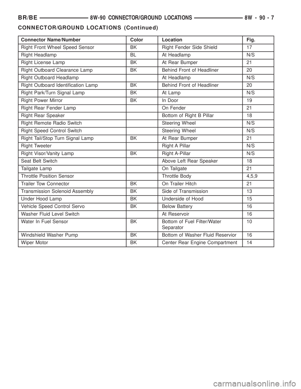
Connector Name/Number Color Location Fig.
Right Front Wheel Speed Sensor BK Right Fender Side Shield 17
Right Headlamp BL At Headlamp N/S
Right License Lamp BK At Rear Bumper 21
Right Outboard Clearance Lamp BK Behind Front of Headliner 20
Right Outboard Headlamp At Headlamp N/S
Right Outboard Identification Lamp BK Behind Front of Headliner 20
Right Park/Turn Signal Lamp BK At Lamp N/S
Right Power Mirror BK In Door 19
Right Rear Fender Lamp On Fender 21
Right Rear Speaker Bottom of Right B Pillar 18
Right Remote Radio Switch Steering Wheel N/S
Right Speed Control Switch Steering Wheel N/S
Right Tail/Stop Turn Signal Lamp BK At Rear Bumper 21
Right Tweeter Right A Pillar N/S
Right Visor/Vanity Lamp BK Right A-Pillar N/S
Seat Belt Switch Above Left Rear Speaker 18
Tailgate Lamp On Tailgate 21
Throttle Position Sensor Throttle Body 4,5,9
Trailer Tow Connector BK On Trailer Hitch 21
Transmission Solenoid Assembly BK Side of Transmission 13
Under Hood Lamp BK Underside of Hood 15
Vehicle Speed Control Servo BK Below Battery 16
Washer Fluid Level Switch At Reservoir 16
Water In Fuel Sensor BK Bottom of Fuel Filter/Water
Separator10
Windshield Washer Pump BK Bottom of Washer Fluid Reservior 16
Wiper Motor BK Center Rear Engine Compartment 14
BR/BE8W-90 CONNECTOR/GROUND LOCATIONS 8W - 90 - 7
CONNECTOR/GROUND LOCATIONS (Continued)
Page 1158 of 2889
(4) A controlled hone motor speed between 200 and
300 RPM is necessary to obtain the proper cross-
hatch angle. The number of up and down strokes per
minute can be regulated to get the desired 50É to 60É
angle. Faster up and down strokes increase the cross-
hatch angle.
(5) After honing, it is necessary that the block be
cleaned to remove all traces of abrasive. Use a brush
to wash parts with a solution of hot water and deter-
gent. Dry parts thoroughly. Use a clean, white, lint-
free cloth to check that the bore is clean. Oil the
bores after cleaning to prevent rusting.
STANDARD PROCEDUREÐHYDROSTATIC
LOCK
CAUTION: DO NOT use the starter motor to rotate
the crankshaft. Severe damage could occur.
When an engine is suspected of hydrostatic lock
(regardless of what caused the problem), follow the
steps below.
(1) Perform the Fuel Pressure Release Procedure
(Refer to 14 - FUEL SYSTEM/FUEL DELIVERY -
STANDARD PROCEDURE).
(2) Disconnect the negative cable(s) from the bat-
tery.
(3) Inspect air cleaner, induction system, and
intake manifold to ensure system is dry and clear of
foreign material.
(4) Place a shop towel around the spark plugs to
catch any fluid that may possibly be under pressure
in the cylinder head. Remove the spark plugs.
(5) With all spark plugs removed, rotate the crank-
shaft using a breaker bar and socket.
(6) Identify the fluid in the cylinders (coolant, fuel,
oil, etc.).
(7) Be sure all fluid has been removed from the
cylinders.
(8) Repair engine or components as necessary to
prevent this problem from occurring again.
(9) Squirt a small amount of engine oil into the
cylinders to lubricate the walls. This will prevent
damage on restart.
(10) Install new spark plugs. Tighten the spark
plugs to 41 N´m (30 ft. lbs.) torque.
(11) Drain engine oil. Remove and discard the oil
filter.
(12) Install the drain plug. Tighten the plug to 34
N´m (25 ft. lbs.) torque.
(13) Install a new oil filter.
(14) Fill engine crankcase with the specified
amount and grade of oil. (Refer to LUBRICATION &
MAINTENANCE - SPECIFICATIONS).
(15) Connect the negative cable(s) to the battery.
(16) Start the engine and check for any leaks.
STANDARD PROCEDUREÐREPAIR DAMAGED
OR WORN THREADS
CAUTION: Be sure that the tapped holes maintain
the original center line.
Damaged or worn threads can be repaired. Essen-
tially, this repair consists of:
²Drilling out worn or damaged threads.
²Tapping the hole with a special Heli-Coil Tap, or
equivalent.
²Installing an insert into the tapped hole to bring
the hole back to its original thread size.
STANDARD PROCEDUREÐFORM-IN-PLACE
GASKETS & SEALERS
There are numerous places where form-in-place
gaskets are used on the engine. Care must be taken
when applying form-in-place gaskets to assure
obtaining the desired results.Do not use form-in-
place gasket material unless specified.Bead size,
continuity, and location are of great importance. Too
thin a bead can result in leakage while too much can
result in spill-over which can break off and obstruct
fluid feed lines. A continuous bead of the proper
width is essential to obtain a leak-free gasket.
There are numerous types of form-in-place gasket
materials that are used in the engine area. Mopart
Engine RTV GEN II, MopartATF-RTV, and Mopart
Gasket Maker gasket materials, each have different
properties and can not be used in place of the other.
MOPARtENGINE RTV GEN II
MopartEngine RTV GEN II is used to seal com-
ponents exposed to engine oil. This material is a spe-
cially designed black silicone rubber RTV that
retains adhesion and sealing properties when
exposed to engine oil. Moisture in the air causes the
material to cure. This material is available in three
ounce tubes and has a shelf life of one year. After one
year this material will not properly cure. Always
inspect the package for the expiration date before
use.
MOPARtATF RTV
MopartATF RTV is a specifically designed black
silicone rubber RTV that retains adhesion and seal-
ing properties to seal components exposed to auto-
matic transmission fluid, engine coolants, and
moisture. This material is available in three ounce
tubes and has a shelf life of one year. After one year
this material will not properly cure. Always inspect
the package for the expiration date before use.
MOPARtGASKET MAKER
MopartGasket Maker is an anaerobic type gasket
material. The material cures in the absence of air
when squeezed between two metallic surfaces. It will
not cure if left in the uncovered tube. The anaerobic
BR/BEENGINE 3.9L 9 - 11
ENGINE 3.9L (Continued)
Page 1319 of 2889
LUBRICATION
DESCRIPTION..........................214
OPERATION............................214
DIAGNOSIS AND TESTING................215
ENGINE OIL LEAKS....................215
ENGINE OIL PRESSURE................215
OIL
STANDARD PROCEDURE.................217
ENGINE OIL..........................217
OIL FILTER
REMOVAL.............................218
INSTALLATION..........................218
OIL PAN
REMOVAL.............................218
CLEANING.............................218
INSPECTION...........................219
INSTALLATION..........................219
OIL PUMP
REMOVAL.............................219
CLEANING.............................220
INSPECTION...........................220
INSTALLATION..........................221INTAKE MANIFOLD
DESCRIPTION..........................222
DIAGNOSIS AND TESTING................222
INTAKE MANIFOLD LEAKAGE............222
REMOVAL.............................222
CLEANING.............................223
INSPECTION...........................223
INSTALLATION..........................223
EXHAUST MANIFOLD
DESCRIPTION..........................224
OPERATION............................224
REMOVAL.............................225
CLEANING.............................225
INSPECTION...........................225
INSTALLATION..........................225
TIMING BELT / CHAIN COVER(S)
REMOVAL.............................225
INSTALLATION..........................226
TIMING BELT/CHAIN AND SPROCKETS
REMOVAL.............................226
INSPECTION...........................227
INSTALLATION..........................227
ENGINE 8.0L
DESCRIPTION
The 8.0 Liter (488 CID) ten-cylinder engine is a
V-Type lightweight, single cam, overhead valveengine with hydraulic roller tappets. This engine is
designed for unleaded fuel.
Engine lubrication system consists of a gerotor type
oil pump mounted in the timing chain cover and driven
by the crankshaft. The V-10 uses a full flow oil filter.
The cylinders are numbered from front to rear; 1, 3,
5, 7, 9 on the left bank and 2, 4, 6, 8, 10 on the right
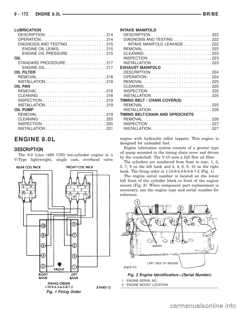
bank. The firing order is 1-10-9-4-3-6-5-8-7-2 (Fig. 1).
The engine serial number is located on the lower
left front of the cylinder block in front of the engine
mount (Fig. 2). When component part replacement is
necessary, use the engine type and serial number for
reference.
Fig. 1 Firing Order
Fig. 2 Engine IdentificationÐ(Serial Number)
1 - ENGINE SERIAL NO.
2 - ENGINE MOUNT LOCATION
9 - 172 ENGINE 8.0LBR/BE
Page 1328 of 2889
MOPARtGASKET SEALANT
MopartGasket Sealant is a slow drying, perma-
nently soft sealer. This material is recommended for
sealing threaded fittings and gaskets against leakage
of oil and coolant. Can be used on threaded and
machined parts under all temperatures. This mate-
rial is used on engines with multi-layer steel (MLS)
cylinder head gaskets. This material also will pre-
vent corrosion. MopartGasket Sealant is available in
a 13 oz. aerosol can or 4oz./16 oz. can w/applicator.
FORM-IN-PLACE GASKET AND SEALER
APPLICATION
Assembling parts using a form-in-place gasket
requires care but it's easier then using precut gas-
kets.
MopartGasket Maker material should be applied
sparingly 1 mm (0.040 in.) diameter or less of sealant
to one gasket surface. Be certain the material sur-
rounds each mounting hole. Excess material can eas-
ily be wiped off. Components should be torqued in
place within 15 minutes. The use of a locating dowel
is recommended during assembly to prevent smear-
ing material off the location.
MopartEngine RTV GEN II or ATF RTV gasket
material should be applied in a continuous bead
approximately 3 mm (0.120 in.) in diameter. All
mounting holes must be circled. For corner sealing, a
3.17 or 6.35 mm (1/8 or 1/4 in.) drop is placed in the
center of the gasket contact area. Uncured sealant
may be removed with a shop towel. Components
should be torqued in place while the sealant is still
wet to the touch (within 10 minutes). The usage of a
locating dowel is recommended during assembly to
prevent smearing material off the location.
MopartGasket Sealant in an aerosol can should be
applied using a thin, even coat sprayed completely
over both surfaces to be joined, and both sides of a
gasket. Then proceed with assembly. Material in a
can w/applicator can be brushed on evenly over the
sealing surfaces. Material in an aerosol can should be
used on engines with multi-layer steel gaskets.
STANDARD PROCEDUREÐREPAIR DAMAGED
OR WORN THREADS
CAUTION: Be sure that the tapped holes maintain
the original center line.
Damaged or worn threads can be repaired. Essen-
tially, this repair consists of:
²Drilling out worn or damaged threads.
²Tapping the hole with a special Heli-Coil Tap, or
equivalent.
²Installing an insert into the tapped hole to bring
the hole back to its original thread size.
STANDARD PROCEDUREÐHYDROSTATIC
LOCK
CAUTION: DO NOT use the starter motor to rotate
the crankshaft. Severe damage could occur.
When an engine is suspected of hydrostatic lock
(regardless of what caused the problem), follow the
steps below.
(1) Perform the Fuel Pressure Release Procedure
(Refer to 14 - FUEL SYSTEM/FUEL DELIVERY -
STANDARD PROCEDURE).
(2) Disconnect the negative cable(s) from the bat-
tery.
(3) Inspect air cleaner, induction system, and
intake manifold to ensure system is dry and clear of
foreign material.
(4) Place a shop towel around the spark plugs to
catch any fluid that may possibly be under pressure
in the cylinder head. Remove the spark plugs.
(5) With all spark plugs removed, rotate the crank-
shaft using a breaker bar and socket.
(6) Identify the fluid in the cylinders (coolant, fuel,
oil, etc.).
(7) Be sure all fluid has been removed from the
cylinders.
(8) Repair engine or components as necessary to
prevent this problem from occurring again.
(9) Squirt a small amount of engine oil into the
cylinders to lubricate the walls. This will prevent
damage on restart.
(10) Install new spark plugs. Tighten the spark
plugs to 41 N´m (30 ft. lbs.) torque.
(11) Drain engine oil. Remove and discard the oil
filter.
(12) Install the drain plug. Tighten the plug to 34
N´m (25 ft. lbs.) torque.
(13) Install a new oil filter.
(14) Fill engine crankcase with the specified
amount and grade of oil. (Refer to LUBRICATION &
MAINTENANCE - SPECIFICATIONS).
(15) Connect the negative cable(s) to the battery.
(16) Start the engine and check for any leaks.
REMOVAL
(1) Remove the battery.
(2) Drain cooling system (Refer to 7 - COOLING -
STANDARD PROCEDURE).
(3) Discharge the air conditioning system, if
equipped (Refer to 24 - HEATING & AIR CONDI-
TIONING/PLUMBING - STANDARD PROCEDURE).
(4) Remove the upper crossmember.
(5) Remove the transmission oil cooler (Refer to 7 -
COOLING/TRANSMISSION/TRANS COOLER -
REMOVAL).
BR/BEENGINE 8.0L 9 - 181
ENGINE 8.0L (Continued)