length DODGE RAM 2001 Service Repair Manual
[x] Cancel search | Manufacturer: DODGE, Model Year: 2001, Model line: RAM, Model: DODGE RAM 2001Pages: 2889, PDF Size: 68.07 MB
Page 19 of 2889
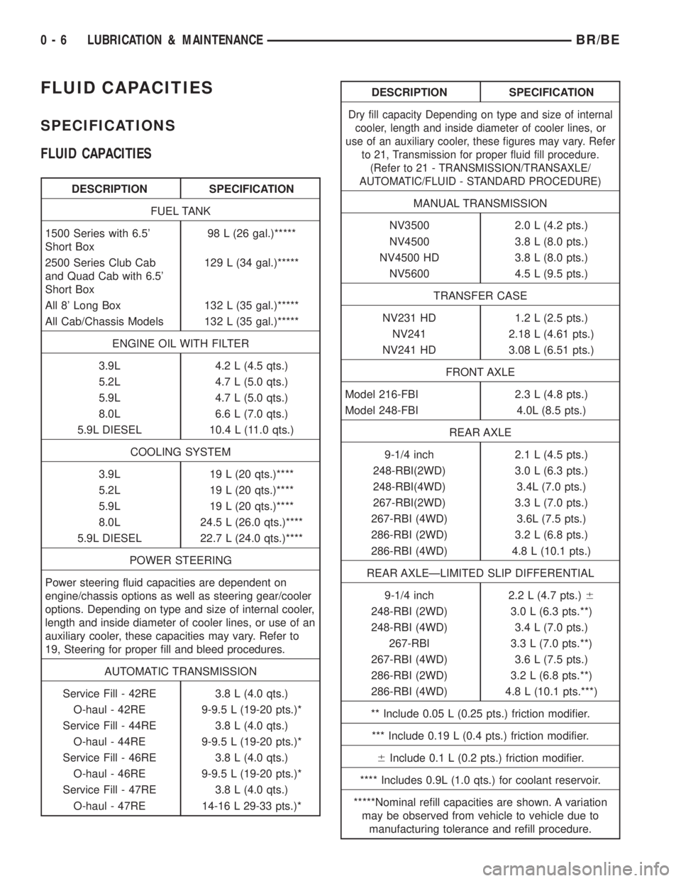
FLUID CAPACITIES
SPECIFICATIONS
FLUID CAPACITIES
DESCRIPTION SPECIFICATION
FUEL TANK
1500 Series with 6.5'
Short Box98 L (26 gal.)*****
2500 Series Club Cab
and Quad Cab with 6.5'
Short Box129 L (34 gal.)*****
All 8' Long Box 132 L (35 gal.)*****
All Cab/Chassis Models 132 L (35 gal.)*****
ENGINE OIL WITH FILTER
3.9L 4.2 L (4.5 qts.)
5.2L 4.7 L (5.0 qts.)
5.9L 4.7 L (5.0 qts.)
8.0L 6.6 L (7.0 qts.)
5.9L DIESEL 10.4 L (11.0 qts.)
COOLING SYSTEM
3.9L 19 L (20 qts.)****
5.2L 19 L (20 qts.)****
5.9L 19 L (20 qts.)****
8.0L 24.5 L (26.0 qts.)****
5.9L DIESEL 22.7 L (24.0 qts.)****
POWER STEERING
Power steering fluid capacities are dependent on
engine/chassis options as well as steering gear/cooler
options. Depending on type and size of internal cooler,
length and inside diameter of cooler lines, or use of an
auxiliary cooler, these capacities may vary. Refer to
19, Steering for proper fill and bleed procedures.
AUTOMATIC TRANSMISSION
Service Fill - 42RE 3.8 L (4.0 qts.)
O-haul - 42RE 9-9.5 L (19-20 pts.)*
Service Fill - 44RE 3.8 L (4.0 qts.)
O-haul - 44RE 9-9.5 L (19-20 pts.)*
Service Fill - 46RE 3.8 L (4.0 qts.)
O-haul - 46RE 9-9.5 L (19-20 pts.)*
Service Fill - 47RE 3.8 L (4.0 qts.)
O-haul - 47RE 14-16 L 29-33 pts.)*
DESCRIPTION SPECIFICATION
Dry fill capacity Depending on type and size of internal
cooler, length and inside diameter of cooler lines, or
use of an auxiliary cooler, these figures may vary. Refer
to 21, Transmission for proper fluid fill procedure.
(Refer to 21 - TRANSMISSION/TRANSAXLE/
AUTOMATIC/FLUID - STANDARD PROCEDURE)
MANUAL TRANSMISSION
NV3500 2.0 L (4.2 pts.)
NV4500 3.8 L (8.0 pts.)
NV4500 HD 3.8 L (8.0 pts.)
NV5600 4.5 L (9.5 pts.)
TRANSFER CASE
NV231 HD 1.2 L (2.5 pts.)
NV241 2.18 L (4.61 pts.)
NV241 HD 3.08 L (6.51 pts.)
FRONT AXLE
Model 216-FBI 2.3 L (4.8 pts.)
Model 248-FBI 4.0L (8.5 pts.)
REAR AXLE
9-1/4 inch 2.1 L (4.5 pts.)
248-RBI(2WD) 3.0 L (6.3 pts.)
248-RBI(4WD) 3.4L (7.0 pts.)
267-RBI(2WD) 3.3 L (7.0 pts.)
267-RBI (4WD) 3.6L (7.5 pts.)
286-RBI (2WD) 3.2 L (6.8 pts.)
286-RBI (4WD) 4.8 L (10.1 pts.)
REAR AXLEÐLIMITED SLIP DIFFERENTIAL
9-1/4 inch 2.2 L (4.7 pts.)6
248-RBI (2WD) 3.0 L (6.3 pts.**)
248-RBI (4WD) 3.4 L (7.0 pts.)
267-RBI 3.3 L (7.0 pts.**)
267-RBI (4WD) 3.6 L (7.5 pts.)
286-RBI (2WD) 3.2 L (6.8 pts.**)
286-RBI (4WD) 4.8 L (10.1 pts.***)
** Include 0.05 L (0.25 pts.) friction modifier.
*** Include 0.19 L (0.4 pts.) friction modifier.
6Include 0.1 L (0.2 pts.) friction modifier.
**** Includes 0.9L (1.0 qts.) for coolant reservoir.
*****Nominal refill capacities are shown. A variation
may be observed from vehicle to vehicle due to
manufacturing tolerance and refill procedure.
0 - 6 LUBRICATION & MAINTENANCEBR/BE
Page 71 of 2889
SPECIAL TOOLS
SUSPENSION-REAR
BUSHINGS
REMOVAL
(1) Remove the spring from the vehicle.
(2) Position the spring eye in a press.
(3) Press the bushing out with an appropriate size
driver.
INSTALLATION
(1) Press new bushing into the spring eye with an
appropriate size driver. The bushing should be cen-
tered in the spring eye.
(2) Install the spring on the vehicle.
JOUNCE BUMPER
DESCRIPTION
The jounce bumpers are bolted to the frame rail
above the axle.
OPERATION
The jounce bumpers are used to limit the spring
and axle travel.
SHOCK
DESCRIPTION
The top of the shock absorbers are bolted to the
body crossmember. The bottom of the shocks are
bolted to the axle bracket.
OPERATION
The shocks dampen the jounce and rebound as the
vehicle travels over various road conditions.
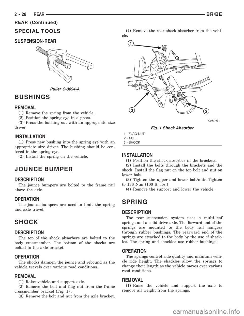
REMOVAL
(1) Raise vehicle and support axle.
(2) Remove the bolt and flag nut from the frame
crossmember bracket (Fig. 1) .
(3) Remove the bolt and nut from the axle bracket.(4) Remove the rear shock absorber from the vehi-
cle.
INSTALLATION
(1) Position the shock absorber in the brackets.
(2) Install the bolts through the brackets and the
shock. Install the flag nut on the top bolt and nut on
lower bolt.
(3) Tighten the upper and lower bolt/nuts Tighten
to 136 N.m (100 ft. lbs.)
(4) Remove the support and lower the vehicle.
SPRING
DESCRIPTION
The rear suspension system uses a multi-leaf
springs and a solid drive axle. The forward end of the
springs are mounted to the body rail hangers
through rubber bushings. The rearward end of the
springs are attached to the body by the use of shack-
les. The spring and shackles use rubber bushings.
OPERATION
The springs control ride quality and maintain vehi-
cle ride height. The shackles allow the springs to
change their length as the vehicle moves over various
road conditions.
REMOVAL
(1) Raise the vehicle and support the axle to
remove all weight from the springs.
Puller C-3894-A
Fig. 1 Shock Absorber
1 - FLAG NUT
2 - AXLE
3 - SHOCK
2 - 28 REARBR/BE
REAR (Continued)
Page 74 of 2889
DIFFERENTIAL & DRIVELINE
TABLE OF CONTENTS
page page
PROPELLER SHAFT.......................1
FRONT AXLE - 216FBI....................12
FRONT AXLE - 248FBI....................45
REAR AXLE-91/4.......................77REAR AXLE - 248RBI....................109
REAR AXLE - 267RBI....................140
REAR AXLE - 286RBI....................169
PROPELLER SHAFT
TABLE OF CONTENTS
page page
PROPELLER SHAFT
DESCRIPTION............................1
OPERATION.............................1
DIAGNOSIS AND TESTING..................3
PROPELLER SHAFT.....................3
STANDARD PROCEDURE...................5
SPECIFICATIONS.........................8
SPECIAL TOOLS..........................8
PROPELLER SHAFT - FRONT
REMOVAL...............................8
INSTALLATION............................8PROPELLER SHAFT - REAR
REMOVAL...............................9
INSTALLATION............................9
CENTER BEARING
DESCRIPTION...........................10
OPERATION.............................10
REMOVAL..............................10
INSTALLATION...........................10
ADJUSTMENTS..........................10
SINGLE CARDAN UNIVERSAL JOINTS
DISASSEMBLY...........................11
PROPELLER SHAFT
DESCRIPTION
A propeller shaft (Fig. 1), (Fig. 2), (Fig. 3), and
(Fig. 4) is a shaft which connects the transmission/
transfer case to the axle differential. This is the link
through which the engine power is transmitted to the
axle.
The propeller shaft is designed and built with the
yoke lugs in line with each other which is called zero
phasing. This design produces the smoothest running
condition, an out-of-phase shaft can cause a vibra-
tion.
Tubular propeller shafts are balanced by the man-
ufacturer with weights spot welded to the tube.
Use the exact replacement parts when installing
the propeller shafts. The use of the correct replace-
ment parts helps to ensure safe operation. All fasten-
ers must be torqued to the specified values for safe
operation.Also make alignment reference marks (Fig. 5)on
the propeller shaft yoke and axle, or transmission,
yoke prior to servicing. This helps to eliminate possi-
ble vibration.
CAUTION: Do not allow the propeller shaft to drop
or hang from any propeller shaft joint during
removal. Attach the propeller shaft to the vehicle
underside with wire to prevent damage to the joints.
OPERATION
The propeller shaft must operate through con-
stantly changing relative angles between the trans-
mission and axle. It must also be capable of changing
length while transmitting torque. The axle rides sus-
pended by springs in a floating motion. The propeller
shaft must be able to change operating angles when
going over various road surfaces. This is accom-
plished through universal joints, which permit the
propeller shaft to operate at different angles. The slip
joints (or yokes) permit contraction or expansion.
BR/BEDIFFERENTIAL & DRIVELINE 3 - 1
Page 78 of 2889
(15) If the vibration remains unacceptable, apply
the same steps to the front end of the propeller shaft.
(16) Install the wheel and tires. Lower the vehicle.
RUNOUT
(1) Remove dirt, rust, paint and undercoating from
the propeller shaft surface where the dial indicator
will contact the shaft.
(2) The dial indicator must be installed perpendic-
ular to the shaft surface.
(3) Measure runout at the center and ends of the
shaft sufficiently far away from weld areas to ensure
that the effects of the weld process will not enter into
the measurements.
(4) Refer to Runout Specifications chart.
(5) If the propeller shaft runout is out of specifica-
tion, remove the propeller shaft, index the shaft 180É,
and re-install the propeller shaft. Measure shaft
runout again.
(6) If the propeller shaft runout is now within
specifications, mark the shaft and yokes for proper
orientation.
(7) If the propeller shaft runout is not within spec-
ifications, verify that the runout of the transmission/
transfer case and axle are within specifications.
Correct as necessary and re-measure propeller shaft
runout.
(8) Replace the propeller shaft if the runout still
exceeds the limits.
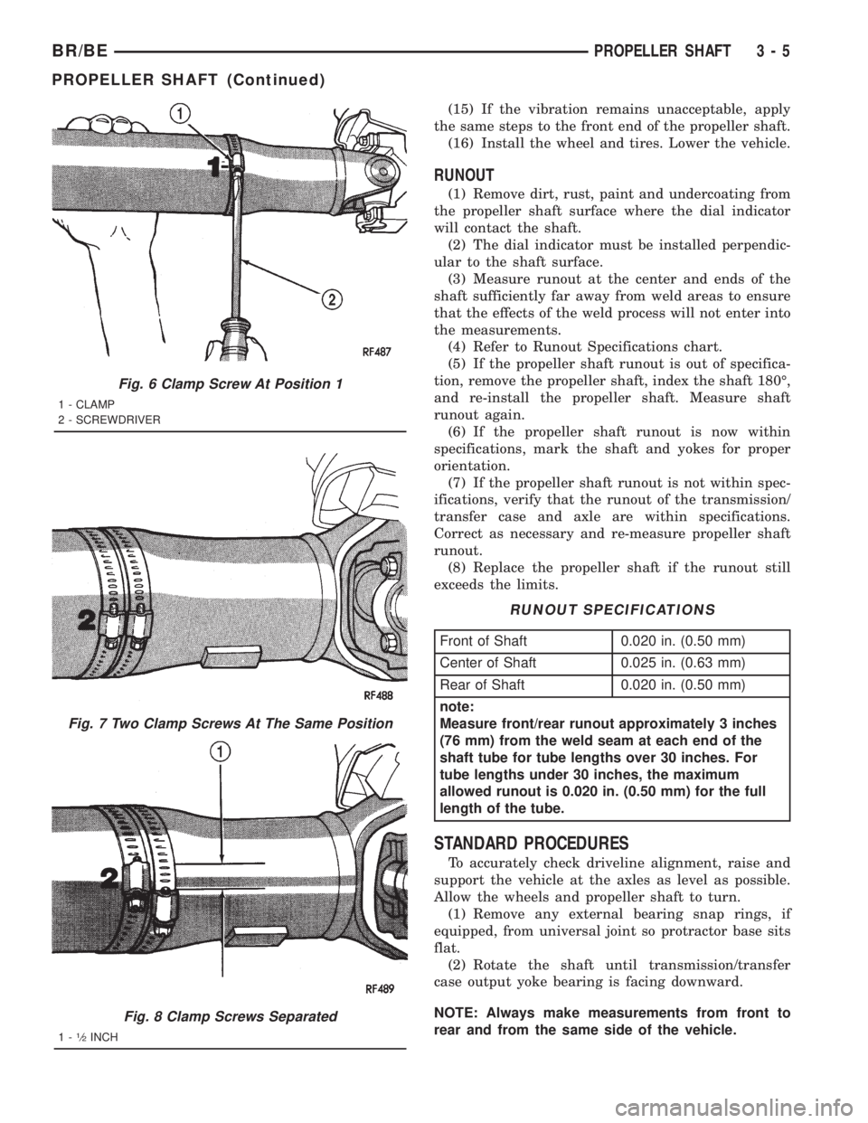
RUNOUT SPECIFICATIONS
Front of Shaft 0.020 in. (0.50 mm)
Center of Shaft 0.025 in. (0.63 mm)
Rear of Shaft 0.020 in. (0.50 mm)
note:
Measure front/rear runout approximately 3 inches
(76 mm) from the weld seam at each end of the
shaft tube for tube lengths over 30 inches. For
tube lengths under 30 inches, the maximum
allowed runout is 0.020 in. (0.50 mm) for the full
length of the tube.
STANDARD PROCEDURES
To accurately check driveline alignment, raise and
support the vehicle at the axles as level as possible.
Allow the wheels and propeller shaft to turn.
(1) Remove any external bearing snap rings, if
equipped, from universal joint so protractor base sits
flat.
(2) Rotate the shaft until transmission/transfer
case output yoke bearing is facing downward.
NOTE: Always make measurements from front to
rear and from the same side of the vehicle.
Fig. 6 Clamp Screw At Position 1
1 - CLAMP
2 - SCREWDRIVER
Fig. 7 Two Clamp Screws At The Same Position
Fig. 8 Clamp Screws Separated
1-1¤2INCH
BR/BEPROPELLER SHAFT 3 - 5
PROPELLER SHAFT (Continued)
Page 83 of 2889
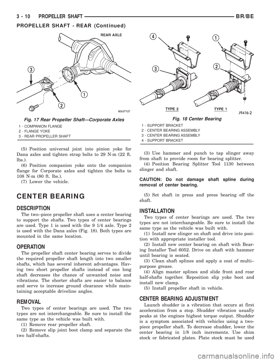
(5) Position universal joint into pinion yoke for
Dana axles and tighten strap bolts to 29 N´m (22 ft.
lbs.).
(6) Position companion yoke onto the companion
flange for Corporate axles and tighten the bolts to
108 N´m (80 ft. lbs.).
(7) Lower the vehicle.
CENTER BEARING
DESCRIPTION
The two±piece propeller shaft uses a center bearing
to support the shafts. Two types of center bearings
are used. Type 1 is used with the 9 1/4 axle. Type 2
is used with the Dana axles (Fig. 18). Both types are
mounted in the same location.
OPERATION
The propeller shaft center bearing serves to divide
the required propeller shaft length into two smaller
shafts, which has several inherent advantages. Hav-
ing two short propeller shafts instead of one long
shaft decreases the chance of unwanted noise and
vibrations. The shorter shafts are easier to balance
and serve to increase ground clearance while main-
taining acceptable driveline angles.
REMOVAL
Two types of center bearings are used. The two
types are not interchangeable. Be sure to install the
same type as the vehicle was built with.
(1) Remove rear propeller shaft.
(2) Remove slip joint boot clamp and separate the
two half-shafts.(3) Use hammer and punch to tap slinger away
from shaft to provide room for bearing splitter.
(4) Position Bearing Splitter Tool 1130 between
slinger and shaft.
CAUTION: Do not damage shaft spline during
removal of center bearing.
(5) Set shaft in press and press bearing off the
shaft.
INSTALLATION
Two types of center bearings are used. The two
types are not interchangeable. Be sure to install the
same type as the vehicle was built with.
(1) Install new slinger on shaft and drive into posi-
tion with appropriate installer tool.
(2) Install new center bearing on shaft with Bear-
ing Installer Tool 6052. Drive on shaft with hammer
until bearing is seated.
(3) Clean shaft splines and apply a coat of multi±
purpose grease.
(4) Align master splines and slide front and rear
half-shafts together. Reposition slip yoke boot and
install new clamp.
(5) Install propeller shaft in vehicle.
CENTER BEARING ADJUSTMENT
Launch shudder is a vibration that occurs at first
acceleration from a stop. Shudder vibration usually
peaks at the engines highest torque output. Shudder
is a symptom associated with vehicles using a two-
piece propeller shaft. To decrease shudder, lower the
center bearing in 1/8 inch increments. Use shim
stock or fabricated plates. Plate stock must be used
Fig. 17 Rear Propeller ShaftÐCorporate Axles
1 - COMPANION FLANGE
2 - FLANGE YOKE
3 - REAR PROPELLER SHAFT
Fig. 18 Center Bearing
1 - SUPPORT BRACKET
2 - CENTER BEARING ASSEMBLY
3 - CENTER BEARING ASSEMBLY
4 - SUPPORT BRACKET
3 - 10 PROPELLER SHAFTBR/BE
PROPELLER SHAFT - REAR (Continued)
Page 84 of 2889
to maintain compression of the rubber insulator
around the bearing. Do not use washers. Replace the
original bolts with the appropriate increased length
bolts.
SINGLE CARDAN UNIVERSAL
JOINTS
DISASSEMBLY
Individual components of cardan universal joints
are not serviceable. If worn or leaking, they must be
replaced as an assembly.
(1) Remove the propeller shaft.
(2) Using a soft drift, tap the outside of the bear-
ing cap assembly to loosen snap ring.
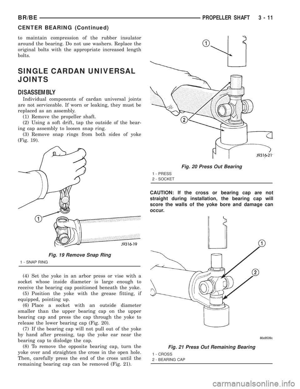
(3) Remove snap rings from both sides of yoke
(Fig. 19).
(4) Set the yoke in an arbor press or vise with a
socket whose inside diameter is large enough to
receive the bearing cap positioned beneath the yoke.
(5) Position the yoke with the grease fitting, if
equipped, pointing up.
(6) Place a socket with an outside diameter
smaller than the upper bearing cap on the upper
bearing cap and press the cap through the yoke to
release the lower bearing cap (Fig. 20).
(7) If the bearing cap will not pull out of the yoke
by hand after pressing, tap the yoke ear near the
bearing cap to dislodge the cap.
(8) To remove the opposite bearing cap, turn the
yoke over and straighten the cross in the open hole.
Then, carefully press the end of the cross until the
remaining bearing cap can be removed (Fig. 21).CAUTION: If the cross or bearing cap are not
straight during installation, the bearing cap will
score the walls of the yoke bore and damage can
occur.
Fig. 19 Remove Snap Ring
1 - SNAP RING
Fig. 20 Press Out Bearing
1 - PRESS
2 - SOCKET
Fig. 21 Press Out Remaining Bearing
1 - CROSS
2 - BEARING CAP
BR/BEPROPELLER SHAFT 3 - 11
CENTER BEARING (Continued)
Page 300 of 2889
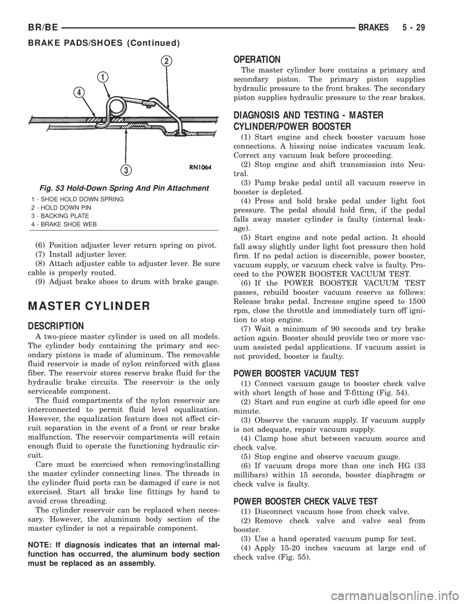
(6) Position adjuster lever return spring on pivot.
(7) Install adjuster lever.
(8) Attach adjuster cable to adjuster lever. Be sure
cable is properly routed.
(9) Adjust brake shoes to drum with brake gauge.
MASTER CYLINDER
DESCRIPTION
A two-piece master cylinder is used on all models.
The cylinder body containing the primary and sec-
ondary pistons is made of aluminum. The removable
fluid reservoir is made of nylon reinforced with glass
fiber. The reservoir stores reserve brake fluid for the
hydraulic brake circuits. The reservoir is the only
serviceable component.
The fluid compartments of the nylon reservoir are
interconnected to permit fluid level equalization.
However, the equalization feature does not affect cir-
cuit separation in the event of a front or rear brake
malfunction. The reservoir compartments will retain
enough fluid to operate the functioning hydraulic cir-
cuit.
Care must be exercised when removing/installing
the master cylinder connecting lines. The threads in
the cylinder fluid ports can be damaged if care is not
exercised. Start all brake line fittings by hand to
avoid cross threading.
The cylinder reservoir can be replaced when neces-
sary. However, the aluminum body section of the
master cylinder is not a repairable component.
NOTE: If diagnosis indicates that an internal mal-
function has occurred, the aluminum body section
must be replaced as an assembly.
OPERATION
The master cylinder bore contains a primary and
secondary piston. The primary piston supplies
hydraulic pressure to the front brakes. The secondary
piston supplies hydraulic pressure to the rear brakes.
DIAGNOSIS AND TESTING - MASTER
CYLINDER/POWER BOOSTER
(1) Start engine and check booster vacuum hose
connections. A hissing noise indicates vacuum leak.
Correct any vacuum leak before proceeding.
(2) Stop engine and shift transmission into Neu-
tral.
(3) Pump brake pedal until all vacuum reserve in
booster is depleted.
(4) Press and hold brake pedal under light foot
pressure. The pedal should hold firm, if the pedal
falls away master cylinder is faulty (internal leak-
age).
(5) Start engine and note pedal action. It should
fall away slightly under light foot pressure then hold
firm. If no pedal action is discernible, power booster,
vacuum supply, or vacuum check valve is faulty. Pro-
ceed to the POWER BOOSTER VACUUM TEST.
(6) If the POWER BOOSTER VACUUM TEST
passes, rebuild booster vacuum reserve as follows:
Release brake pedal. Increase engine speed to 1500
rpm, close the throttle and immediately turn off igni-
tion to stop engine.
(7) Wait a minimum of 90 seconds and try brake
action again. Booster should provide two or more vac-
uum assisted pedal applications. If vacuum assist is
not provided, booster is faulty.
POWER BOOSTER VACUUM TEST
(1) Connect vacuum gauge to booster check valve
with short length of hose and T-fitting (Fig. 54).
(2) Start and run engine at curb idle speed for one
minute.
(3) Observe the vacuum supply. If vacuum supply
is not adequate, repair vacuum supply.
(4) Clamp hose shut between vacuum source and
check valve.
(5) Stop engine and observe vacuum gauge.
(6) If vacuum drops more than one inch HG (33
millibars) within 15 seconds, booster diaphragm or
check valve is faulty.
POWER BOOSTER CHECK VALVE TEST
(1) Disconnect vacuum hose from check valve.
(2) Remove check valve and valve seal from
booster.
(3) Use a hand operated vacuum pump for test.
(4) Apply 15-20 inches vacuum at large end of
check valve (Fig. 55).
Fig. 53 Hold-Down Spring And Pin Attachment
1 - SHOE HOLD DOWN SPRING
2 - HOLD DOWN PIN
3 - BACKING PLATE
4 - BRAKE SHOE WEB
BR/BEBRAKES 5 - 29
BRAKE PADS/SHOES (Continued)
Page 356 of 2889
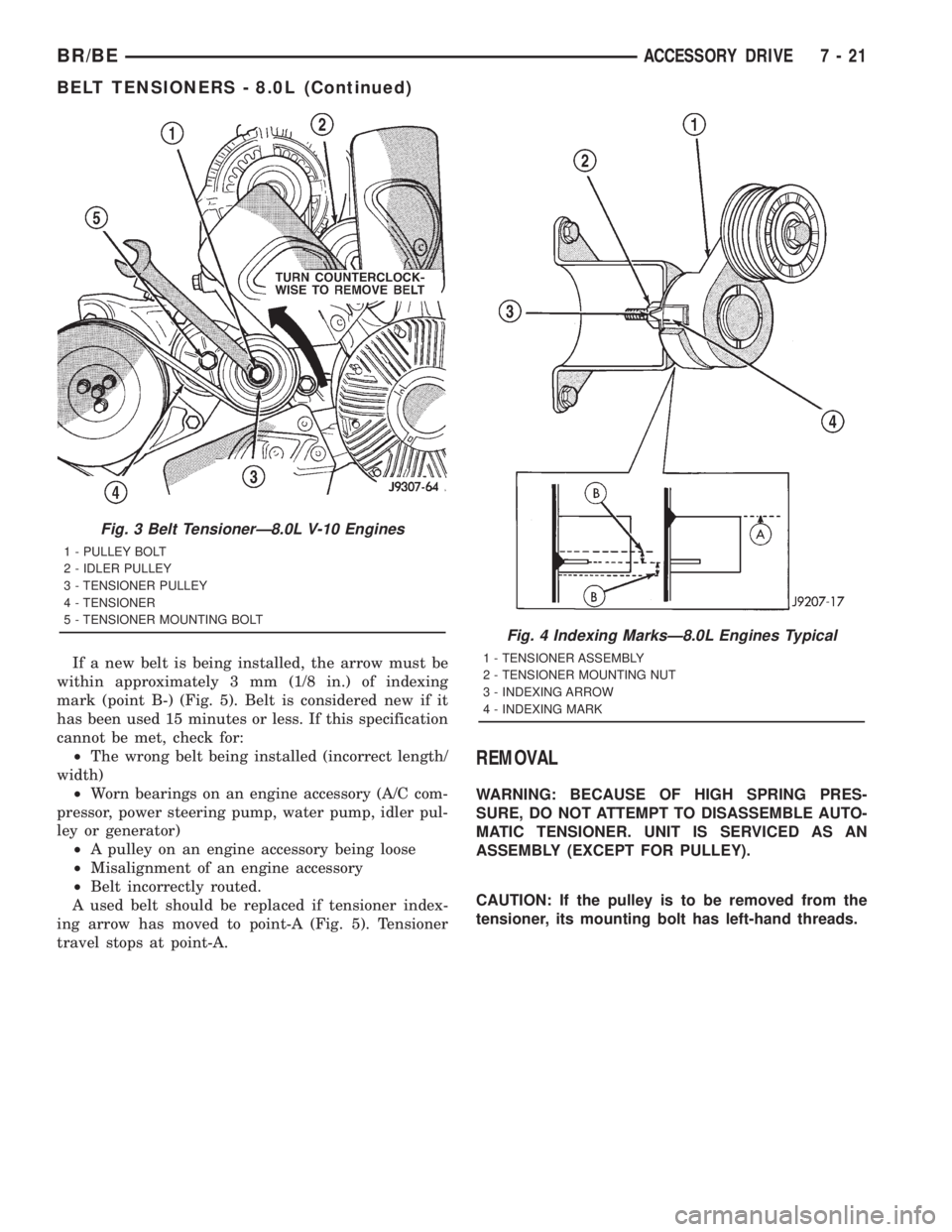
If a new belt is being installed, the arrow must be
within approximately 3 mm (1/8 in.) of indexing
mark (point B-) (Fig. 5). Belt is considered new if it
has been used 15 minutes or less. If this specification
cannot be met, check for:
²The wrong belt being installed (incorrect length/
width)
²Worn bearings on an engine accessory (A/C com-
pressor, power steering pump, water pump, idler pul-
ley or generator)
²A pulley on an engine accessory being loose
²Misalignment of an engine accessory
²Belt incorrectly routed.
A used belt should be replaced if tensioner index-
ing arrow has moved to point-A (Fig. 5). Tensioner
travel stops at point-A.
REMOVAL
WARNING: BECAUSE OF HIGH SPRING PRES-
SURE, DO NOT ATTEMPT TO DISASSEMBLE AUTO-
MATIC TENSIONER. UNIT IS SERVICED AS AN
ASSEMBLY (EXCEPT FOR PULLEY).
CAUTION: If the pulley is to be removed from the
tensioner, its mounting bolt has left-hand threads.
Fig. 3 Belt TensionerÐ8.0L V-10 Engines
1 - PULLEY BOLT
2 - IDLER PULLEY
3 - TENSIONER PULLEY
4 - TENSIONER
5 - TENSIONER MOUNTING BOLT
Fig. 4 Indexing MarksÐ8.0L Engines Typical
1 - TENSIONER ASSEMBLY
2 - TENSIONER MOUNTING NUT
3 - INDEXING ARROW
4 - INDEXING MARK
BR/BEACCESSORY DRIVE 7 - 21
BELT TENSIONERS - 8.0L (Continued)
Page 358 of 2889
BELT TENSIONERS - 5.9L
DIESEL
DESCRIPTION
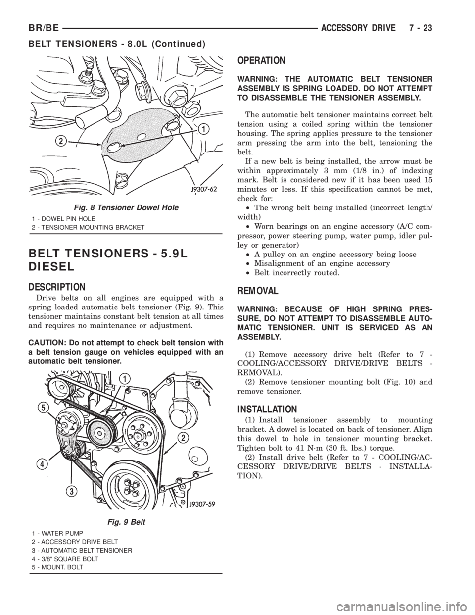
Drive belts on all engines are equipped with a
spring loaded automatic belt tensioner (Fig. 9). This
tensioner maintains constant belt tension at all times
and requires no maintenance or adjustment.
CAUTION: Do not attempt to check belt tension with
a belt tension gauge on vehicles equipped with an
automatic belt tensioner.
OPERATION
WARNING: THE AUTOMATIC BELT TENSIONER
ASSEMBLY IS SPRING LOADED. DO NOT ATTEMPT
TO DISASSEMBLE THE TENSIONER ASSEMBLY.
The automatic belt tensioner maintains correct belt
tension using a coiled spring within the tensioner
housing. The spring applies pressure to the tensioner
arm pressing the arm into the belt, tensioning the
belt.
If a new belt is being installed, the arrow must be
within approximately 3 mm (1/8 in.) of indexing
mark. Belt is considered new if it has been used 15
minutes or less. If this specification cannot be met,
check for:
²The wrong belt being installed (incorrect length/
width)
²Worn bearings on an engine accessory (A/C com-
pressor, power steering pump, water pump, idler pul-
ley or generator)
²A pulley on an engine accessory being loose
²Misalignment of an engine accessory
²Belt incorrectly routed.
REMOVAL
WARNING: BECAUSE OF HIGH SPRING PRES-
SURE, DO NOT ATTEMPT TO DISASSEMBLE AUTO-
MATIC TENSIONER. UNIT IS SERVICED AS AN
ASSEMBLY.
(1) Remove accessory drive belt (Refer to 7 -
COOLING/ACCESSORY DRIVE/DRIVE BELTS -
REMOVAL).
(2) Remove tensioner mounting bolt (Fig. 10) and
remove tensioner.
INSTALLATION
(1) Install tensioner assembly to mounting
bracket. A dowel is located on back of tensioner. Align
this dowel to hole in tensioner mounting bracket.
Tighten bolt to 41 N´m (30 ft. lbs.) torque.
(2) Install drive belt (Refer to 7 - COOLING/AC-
CESSORY DRIVE/DRIVE BELTS - INSTALLA-
TION).
Fig. 8 Tensioner Dowel Hole
1 - DOWEL PIN HOLE
2 - TENSIONER MOUNTING BRACKET
Fig. 9 Belt
1 - WATER PUMP
2 - ACCESSORY DRIVE BELT
3 - AUTOMATIC BELT TENSIONER
4 - 3/89SQUARE BOLT
5 - MOUNT. BOLT
BR/BEACCESSORY DRIVE 7 - 23
BELT TENSIONERS - 8.0L (Continued)
Page 362 of 2889
INSTALLATION
CAUTION: When installing the accessory drive belt,
the belt must be routed correctly. If not, engine may
overheat due to water pump rotating in wrong
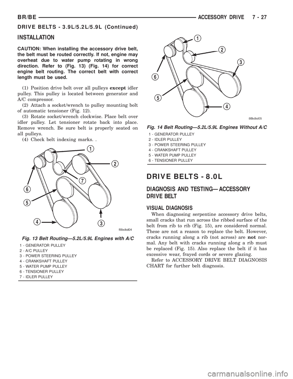
direction. Refer to (Fig. 13) (Fig. 14) for correct
engine belt routing. The correct belt with correct
length must be used.
(1) Position drive belt over all pulleysexceptidler
pulley. This pulley is located between generator and
A/C compressor.
(2) Attach a socket/wrench to pulley mounting bolt
of automatic tensioner (Fig. 12).
(3) Rotate socket/wrench clockwise. Place belt over
idler pulley. Let tensioner rotate back into place.
Remove wrench. Be sure belt is properly seated on
all pulleys.
(4) Check belt indexing marks. .
DRIVE BELTS - 8.0L
DIAGNOSIS AND TESTINGÐACCESSORY
DRIVE BELT
VISUAL DIAGNOSIS
When diagnosing serpentine accessory drive belts,
small cracks that run across the ribbed surface of the
belt from rib to rib (Fig. 15), are considered normal.
These are not a reason to replace the belt. However,
cracks running along a rib (not across) arenotnor-
mal. Any belt with cracks running along a rib must
be replaced (Fig. 15). Also replace the belt if it has
excessive wear, frayed cords or severe glazing.
Refer to ACCESSORY DRIVE BELT DIAGNOSIS
CHART for further belt diagnosis.
Fig. 13 Belt RoutingÐ5.2L/5.9L Engines with A/C
1 - GENERATOR PULLEY
2 - A/C PULLEY
3 - POWER STEERING PULLEY
4 - CRANKSHAFT PULLEY
5 - WATER PUMP PULLEY
6 - TENSIONER PULLEY
7 - IDLER PULLEY
Fig. 14 Belt RoutingÐ5.2L/5.9L Engines Without A/C
1 - GENERATOR PULLEY
2 - IDLER PULLEY
3 - POWER STEERING PULLEY
4 - CRANKSHAFT PULLEY
5 - WATER PUMP PULLEY
6 - TENSIONER PULLEY
BR/BEACCESSORY DRIVE 7 - 27
DRIVE BELTS - 3.9L/5.2L/5.9L (Continued)