run flat DODGE RAM 2001 Service Repair Manual
[x] Cancel search | Manufacturer: DODGE, Model Year: 2001, Model line: RAM, Model: DODGE RAM 2001Pages: 2889, PDF Size: 68.07 MB
Page 78 of 2889
(15) If the vibration remains unacceptable, apply
the same steps to the front end of the propeller shaft.
(16) Install the wheel and tires. Lower the vehicle.
RUNOUT
(1) Remove dirt, rust, paint and undercoating from
the propeller shaft surface where the dial indicator
will contact the shaft.
(2) The dial indicator must be installed perpendic-
ular to the shaft surface.
(3) Measure runout at the center and ends of the
shaft sufficiently far away from weld areas to ensure
that the effects of the weld process will not enter into
the measurements.
(4) Refer to Runout Specifications chart.
(5) If the propeller shaft runout is out of specifica-
tion, remove the propeller shaft, index the shaft 180É,
and re-install the propeller shaft. Measure shaft
runout again.
(6) If the propeller shaft runout is now within
specifications, mark the shaft and yokes for proper
orientation.
(7) If the propeller shaft runout is not within spec-
ifications, verify that the runout of the transmission/
transfer case and axle are within specifications.
Correct as necessary and re-measure propeller shaft
runout.
(8) Replace the propeller shaft if the runout still
exceeds the limits.
RUNOUT SPECIFICATIONS
Front of Shaft 0.020 in. (0.50 mm)
Center of Shaft 0.025 in. (0.63 mm)
Rear of Shaft 0.020 in. (0.50 mm)
note:
Measure front/rear runout approximately 3 inches
(76 mm) from the weld seam at each end of the
shaft tube for tube lengths over 30 inches. For
tube lengths under 30 inches, the maximum
allowed runout is 0.020 in. (0.50 mm) for the full
length of the tube.
STANDARD PROCEDURES
To accurately check driveline alignment, raise and
support the vehicle at the axles as level as possible.
Allow the wheels and propeller shaft to turn.
(1) Remove any external bearing snap rings, if
equipped, from universal joint so protractor base sits
flat.
(2) Rotate the shaft until transmission/transfer
case output yoke bearing is facing downward.
NOTE: Always make measurements from front to
rear and from the same side of the vehicle.
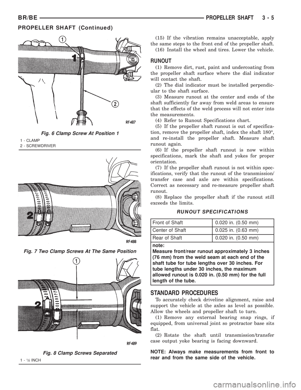
Fig. 6 Clamp Screw At Position 1
1 - CLAMP
2 - SCREWDRIVER
Fig. 7 Two Clamp Screws At The Same Position
Fig. 8 Clamp Screws Separated
1-1¤2INCH
BR/BEPROPELLER SHAFT 3 - 5
PROPELLER SHAFT (Continued)
Page 276 of 2889
WARNING
WARNING: DUST AND DIRT ACCUMULATING ON
BRAKE PARTS DURING NORMAL USE MAY CON-
TAIN ASBESTOS FIBERS FROM PRODUCTION OR
AFTERMARKET LININGS. BREATHING EXCESSIVE
CONCENTRATIONS OF ASBESTOS FIBERS CAN
CAUSE SERIOUS BODILY HARM. EXERCISE CARE
WHEN SERVICING BRAKE PARTS. DO NOT CLEAN
BRAKE PARTS WITH COMPRESSED AIR OR BY
DRY BRUSHING. USE A VACUUM CLEANER SPE-
CIFICALLY DESIGNED FOR THE REMOVAL OF
ASBESTOS FIBERS FROM BRAKE COMPONENTS.
IF A SUITABLE VACUUM CLEANER IS NOT AVAIL-
ABLE, CLEANING SHOULD BE DONE WITH A
WATER DAMPENED CLOTH. DO NOT SAND, OR
GRIND BRAKE LINING UNLESS EQUIPMENT USED
IS DESIGNED TO CONTAIN THE DUST RESIDUE.
DISPOSE OF ALL RESIDUE CONTAINING ASBES-
TOS FIBERS IN SEALED BAGS OR CONTAINERS
TO MINIMIZE EXPOSURE TO YOURSELF AND OTH-
ERS. FOLLOW PRACTICES PRESCRIBED BY THE
OCCUPATIONAL SAFETY AND HEALTH ADMINIS-
TRATION AND THE ENVIRONMENTAL PROTECTION
AGENCY FOR THE HANDLING, PROCESSING, AND
DISPOSITION OF DUST OR DEBRIS THAT MAY
CONTAIN ASBESTOS FIBERS.
CAUTION: Never use gasoline, kerosene, alcohol,
motor oil, transmission fluid, or any fluid containing
mineral oil to clean the system components. These
fluids damage rubber cups and seals. Use only
fresh brake fluid or Mopar brake cleaner to clean or
flush brake system components. These are the only
cleaning materials recommended. If system contam-
ination is suspected, check the fluid for dirt, discol-
oration, or separation into distinct layers. Also
check the reservoir cap seal for distortion. Drain
and flush the system with new brake fluid if con-
tamination is suspected.
CAUTION: Use Mopar brake fluid, or an equivalent
quality fluid meeting SAE/DOT standards J1703 and
DOT 3. Brake fluid must be clean and free of con-
taminants. Use fresh fluid from sealed containers
only to ensure proper antilock component opera-
tion.
CAUTION: Use Mopar multi-mileage or high temper-
ature grease to lubricate caliper slide surfaces,
drum brake pivot pins, and shoe contact points on
the backing plates. Use multi-mileage grease or GE
661 or Dow 111 silicone grease on caliper slide pins
to ensure proper operation.
DIAGNOSIS AND TESTING - BASE BRAKE
SYSTEM
Base brake components consist of the brake shoes,
calipers, wheel cylinders, brake drums, rotors, brake
lines, master cylinder, booster, and parking brake
components.
Brake diagnosis involves determining if the prob-
lem is related to a mechanical, hydraulic, or vacuum
operated component.
The first diagnosis step is the preliminary check.
PRELIMINARY BRAKE CHECK
(1) Check condition of tires and wheels. Damaged
wheels and worn, damaged, or underinflated tires
can cause pull, shudder, vibration, and a condition
similar to grab.
(2) If complaint was based on noise when braking,
check suspension components. Jounce front and rear
of vehicle and listen for noise that might be caused
by loose, worn or damaged suspension or steering
components.
(3) Inspect brake fluid level and condition. Note
that the brake reservoir fluid level will decrease in
proportion to normal lining wear.Also note that
brake fluid tends to darken over time. This is
normal and should not be mistaken for contam-
ination.
(a) If fluid level is abnormally low, look for evi-
dence of leaks at calipers, wheel cylinders, brake
lines, and master cylinder.
(b) If fluid appears contaminated, drain out a
sample to examine. System will have to be flushed
if fluid is separated into layers, or contains a sub-
stance other than brake fluid. The system seals
and cups will also have to be replaced after flush-
ing. Use clean brake fluid to flush the system.
(4) Check parking brake operation. Verify free
movement and full release of cables and pedal. Also
note if vehicle was being operated with parking
brake partially applied.
(5) Check brake pedal operation. Verify that pedal
does not bind and has adequate free play. If pedal
lacks free play, check pedal and power booster for
being loose or for bind condition. Do not road test
until condition is corrected.
(6) Check booster vacuum check valve and hose.
(7) If components checked appear OK, road test
the vehicle.
ROAD TESTING
(1) If complaint involved low brake pedal, pump
pedal and note if it comes back up to normal height.
(2) Check brake pedal response with transmission
in Neutral and engine running. Pedal should remain
firm under constant foot pressure.
BR/BEBRAKES 5 - 5
HYDRAULIC/MECHANICAL (Continued)
Page 665 of 2889
DRIVER POWER SEAT SWITCH
DESCRIPTION
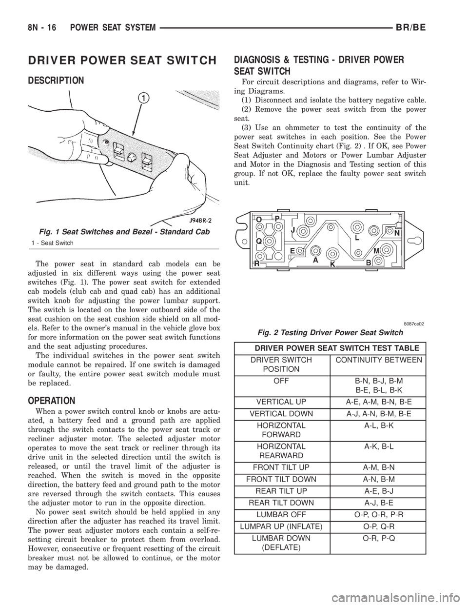
The power seat in standard cab models can be
adjusted in six different ways using the power seat
switches (Fig. 1). The power seat switch for extended
cab models (club cab and quad cab) has an additional
switch knob for adjusting the power lumbar support.
The switch is located on the lower outboard side of the
seat cushion on the seat cushion side shield on all mod-
els. Refer to the owner's manual in the vehicle glove box
for more information on the power seat switch functions
and the seat adjusting procedures.
The individual switches in the power seat switch
module cannot be repaired. If one switch is damaged
or faulty, the entire power seat switch module must
be replaced.
OPERATION
When a power switch control knob or knobs are actu-
ated, a battery feed and a ground path are applied
through the switch contacts to the power seat track or
recliner adjuster motor. The selected adjuster motor
operates to move the seat track or recliner through its
drive unit in the selected direction until the switch is
released, or until the travel limit of the adjuster is
reached. When the switch is moved in the opposite
direction, the battery feed and ground path to the motor
are reversed through the switch contacts. This causes
the adjuster motor to run in the opposite direction.
No power seat switch should be held applied in any
direction after the adjuster has reached its travel limit.
The power seat adjuster motors each contain a self-re-
setting circuit breaker to protect them from overload.
However, consecutive or frequent resetting of the circuit
breaker must not be allowed to continue, or the motor
may be damaged.
DIAGNOSIS & TESTING - DRIVER POWER
SEAT SWITCH
For circuit descriptions and diagrams, refer to Wir-
ing Diagrams.
(1)
Disconnect and isolate the battery negative cable.
(2)Remove the power seat switch from the power
seat.
(3)Use an ohmmeter to test the continuity of the
power seat switches in each position. See the Power
Seat Switch Continuity chart (Fig. 2) . If OK, see Power
Seat Adjuster and Motors or Power Lumbar Adjuster
and Motor in the Diagnosis and Testing section of this
group. If not OK, replace the faulty power seat switch
unit.
DRIVER POWER SEAT SWITCH TEST TABLE
DRIVER SWITCH
POSITIONCONTINUITY BETWEEN
OFF B-N, B-J, B-M
B-E, B-L, B-K
VERTICAL UP A-E, A-M, B-N, B-E
VERTICAL DOWN A-J, A-N, B-M, B-E
HORIZONTAL
FORWARDA-L, B-K
HORIZONTAL
REARWARDA-K, B-L
FRONT TILT UP A-M, B-N
FRONT TILT DOWN A-N, B-M
REAR TILT UP A-E, B-J
REAR TILT DOWN A-J, B-E
LUMBAR OFF O-P, O-R, P-R
LUMPAR UP (INFLATE) O-P, Q-R
LUMBAR DOWN
(DEFLATE)O-R, P-Q
Fig. 1 Seat Switches and Bezel - Standard Cab
1 - Seat Switch
Fig. 2 Testing Driver Power Seat Switch
8N - 16 POWER SEAT SYSTEMBR/BE
Page 668 of 2889
PASSENGER POWER SEAT
SWITCH
DESCRIPTION
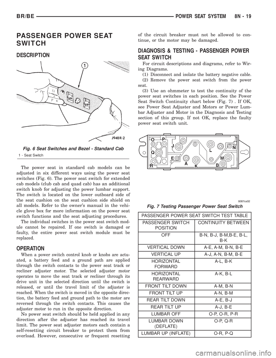
The power seat in standard cab models can be
adjusted in six different ways using the power seat
switches (Fig. 6). The power seat switch for extended
cab models (club cab and quad cab) has an additional
switch knob for adjusting the power lumbar support.
The switch is located on the lower outboard side of
the seat cushion on the seat cushion side shield on
all models. Refer to the owner's manual in the vehi-
cle glove box for more information on the power seat
switch functions and the seat adjusting procedures.
The individual switches in the power seat switch mod-
ule cannot be repaired. If one switch is damaged or
faulty, the entire power seat switch module must be
replaced.
OPERATION
When a power switch control knob or knobs are actu-
ated, a battery feed and a ground path are applied
through the switch contacts to the power seat track or
recliner adjuster motor. The selected adjuster motor
operates to move the seat track or recliner through its
drive unit in the selected direction until the switch is
released, or until the travel limit of the adjuster is
reached. When the switch is moved in the opposite direc-
tion, the battery feed and ground path to the motor are
reversed through the switch contacts. This causes the
adjuster motor to run in the opposite direction.
No power seat switch should be held applied in any
direction after the adjuster has reached its travel
limit. The power seat adjuster motors each contain a
self-resetting circuit breaker to protect them from
overload. However, consecutive or frequent resettingof the circuit breaker must not be allowed to con-
tinue, or the motor may be damaged.
DIAGNOSIS & TESTING - PASSENGER POWER
SEAT SWITCH
For circuit descriptions and diagrams, refer to Wir-
ing Diagrams.
(1)
Disconnect and isolate the battery negative cable.
(2)Remove the power seat switch from the power
seat.
(3) Use an ohmmeter to test the continuity of the
power seat switches in each position. See the Power
Seat Switch Continuity chart below (Fig. 7) . If OK,
see Power Seat Adjuster and Motors or Power Lum-
bar Adjuster and Motor in the Diagnosis and Testing
section of this group. If not OK, replace the faulty
power seat switch unit.
PASSENGER POWER SEAT SWITCH TEST TABLE
PASSENGER SWITCH
POSITIONCONTINUITY BETWEEN
OFF B-N, B-J, B-M,B-E, B-L,
B-K
VERTICAL DOWN A-E, A-M, B-N, B-E
VERTICAL UP A-J, A-N, B-M, B-E
HORIZONTAL
FORWARDA-L, B-K
HORIZONTAL
REARWARDA-K, B-L
FRONT TILT DOWN A-M, B-N
FRONT TILT UP A-N, B-M
REAR TILT DOWN A-E, B-J
REAR TILT UP A-J, B-E
LUMBAR OFF O-P, O-R, P-R
LUMBAR DOWN
(DEFLATE)O-P, Q-R
LUMBAR UP (INFLATE) O-R, P-Q
Fig. 6 Seat Switches and Bezel - Standard Cab
1 - Seat Switch
Fig. 7 Testing Passenger Power Seat Switch
BR/BEPOWER SEAT SYSTEM 8N - 19
Page 1163 of 2889
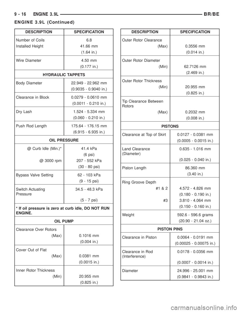
DESCRIPTION SPECIFICATION
Number of Coils 6.8
Installed Height 41.66 mm
(1.64 in.)
Wire Diameter 4.50 mm
(0.177 in.)
HYDRAULIC TAPPETS
Body Diameter 22.949 - 22.962 mm
(0.9035 - 0.9040 in.)
Clearance in Block 0.0279 - 0.0610 mm
(0.0011 - 0.210 in.)
Dry Lash 1.524 - 5.334 mm
(0.060 - 0.210 in.)
Push Rod Length 175.64 - 176.15 mm
(6.915 - 6.935 in.)
OIL PRESSURE
@ Curb Idle (Min.)* 41.4 kPa
(6 psi)
@ 3000 rpm 207 - 552 kPa
(30 - 80 psi)
Bypass Valve Setting 62 - 103 kPa
(9 - 15 psi)
Switch Actuating
Pressure34.5 - 48.3 kPa
(5 - 7 psi)
* If oil pressure is zero at curb idle, DO NOT RUN
ENGINE.
OIL PUMP
Clearance Over Rotors
(Max) 0.1016 mm
(0.004 in.)
Cover Out of Flat
(Max) 0.0381 mm
(0.0015 in.)
Inner Rotor Thickness
(Min) 20.955 mm
(0.825 in.)DESCRIPTION SPECIFICATION
Outer Rotor Clearance
(Max) 0.3556 mm
(0.014 in.)
Outer Rotor Diameter
(Min) 62.7126 mm
(2.469 in.)
Outer Rotor Thickness
(Min) 20.955 mm
(0.825 in.)
Tip Clearance Between
Rotors
(Max) 0.2032 mm
(0.008 in.)
PISTONS
Clearance at Top of Skirt 0.0127 - 0.0381 mm
(0.0005 - 0.0015 in.)
Land Clearance
(Diameter)0.635 - 1.016 mm
(0.025 - 0.040 in.)
Piston Length 86.360 mm
(3.40 in.)
Ring Groove Depth
#1 & 2 4.572 - 4.826 mm
(0.180 - 0.190 in.)
#3 3.810 - 4.064 mm
(0.150 - 0.160 in.)
Weight 592.6 - 596.6 grams
(20.90 - 21.04 oz.)
PISTON PINS
Clearance in Piston 0.0064 - 0.0191 mm
(0.00025 - 0.00075 in.)
Clearance in Rod
(Interference)0.0178 - 0.0356 mm
(0.0007 - 0.0014 in.)
Diameter 24.996 - 25.001 mm
(0.9841 - 0.9843 in.)
9 - 16 ENGINE 3.9LBR/BE
ENGINE 3.9L (Continued)
Page 1278 of 2889
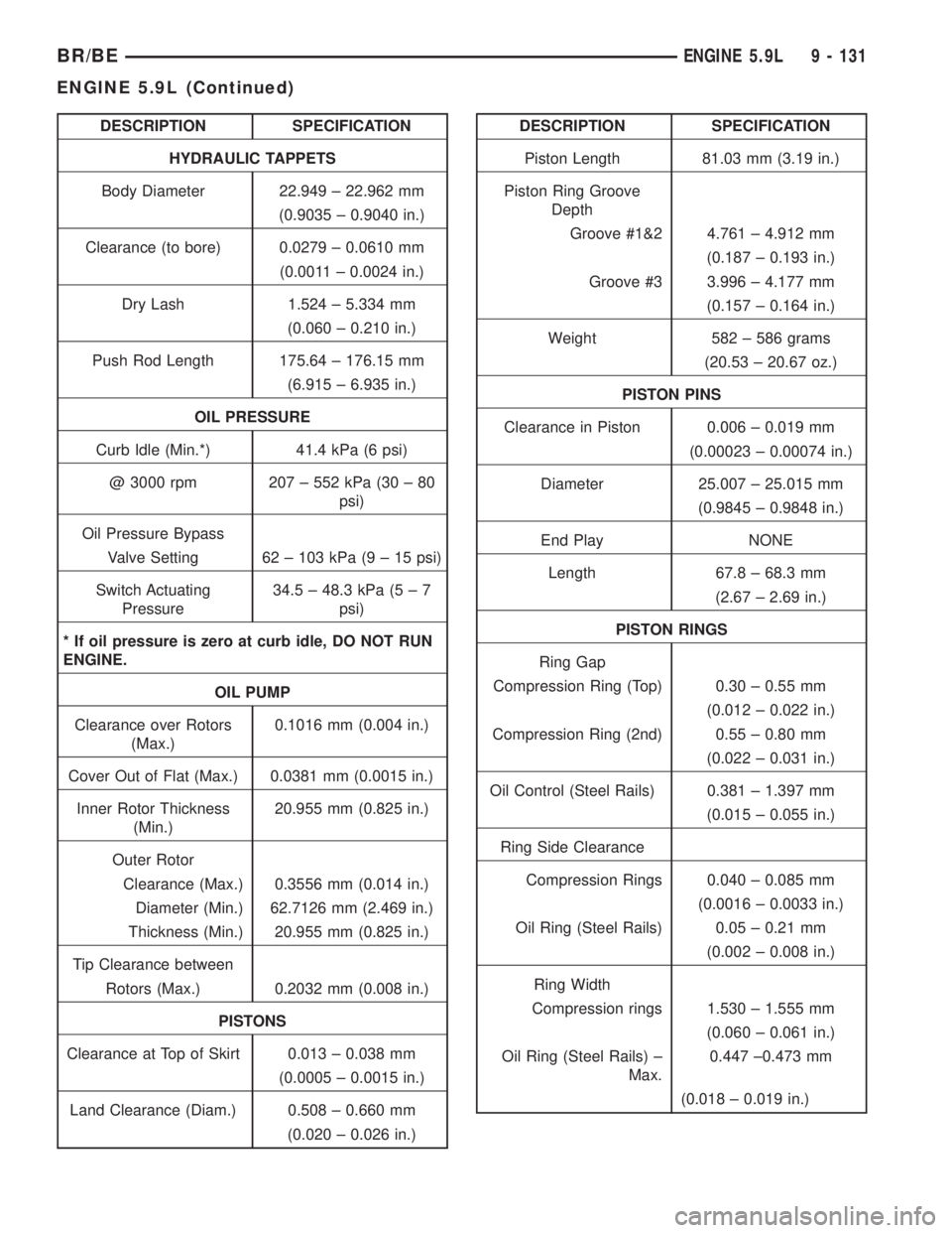
DESCRIPTION SPECIFICATION
HYDRAULIC TAPPETS
Body Diameter 22.949 ± 22.962 mm
(0.9035 ± 0.9040 in.)
Clearance (to bore) 0.0279 ± 0.0610 mm
(0.0011 ± 0.0024 in.)
Dry Lash 1.524 ± 5.334 mm
(0.060 ± 0.210 in.)
Push Rod Length 175.64 ± 176.15 mm
(6.915 ± 6.935 in.)
OIL PRESSURE
Curb Idle (Min.*) 41.4 kPa (6 psi)
@ 3000 rpm 207 ± 552 kPa (30 ± 80
psi)
Oil Pressure Bypass
Valve Setting 62 ± 103 kPa (9 ± 15 psi)
Switch Actuating
Pressure34.5 ± 48.3 kPa (5 ± 7
psi)
* If oil pressure is zero at curb idle, DO NOT RUN
ENGINE.
OIL PUMP
Clearance over Rotors
(Max.)0.1016 mm (0.004 in.)
Cover Out of Flat (Max.) 0.0381 mm (0.0015 in.)
Inner Rotor Thickness
(Min.)20.955 mm (0.825 in.)
Outer Rotor
Clearance (Max.) 0.3556 mm (0.014 in.)
Diameter (Min.) 62.7126 mm (2.469 in.)
Thickness (Min.) 20.955 mm (0.825 in.)
Tip Clearance between
Rotors (Max.) 0.2032 mm (0.008 in.)
PISTONS
Clearance at Top of Skirt 0.013 ± 0.038 mm
(0.0005 ± 0.0015 in.)
Land Clearance (Diam.) 0.508 ± 0.660 mm
(0.020 ± 0.026 in.)DESCRIPTION SPECIFICATION
Piston Length 81.03 mm (3.19 in.)
Piston Ring Groove
Depth
Groove #1&2 4.761 ± 4.912 mm
(0.187 ± 0.193 in.)
Groove #3 3.996 ± 4.177 mm
(0.157 ± 0.164 in.)
Weight 582 ± 586 grams
(20.53 ± 20.67 oz.)
PISTON PINS
Clearance in Piston 0.006 ± 0.019 mm
(0.00023 ± 0.00074 in.)
Diameter 25.007 ± 25.015 mm
(0.9845 ± 0.9848 in.)
End Play NONE
Length 67.8 ± 68.3 mm
(2.67 ± 2.69 in.)
PISTON RINGS
Ring Gap
Compression Ring (Top) 0.30 ± 0.55 mm
(0.012 ± 0.022 in.)
Compression Ring (2nd) 0.55 ± 0.80 mm
(0.022 ± 0.031 in.)
Oil Control (Steel Rails) 0.381 ± 1.397 mm
(0.015 ± 0.055 in.)
Ring Side Clearance
Compression Rings 0.040 ± 0.085 mm
(0.0016 ± 0.0033 in.)
Oil Ring (Steel Rails) 0.05 ± 0.21 mm
(0.002 ± 0.008 in.)
Ring Width
Compression rings 1.530 ± 1.555 mm
(0.060 ± 0.061 in.)
Oil Ring (Steel Rails) ±
Max.0.447 ±0.473 mm
(0.018 ± 0.019 in.)
BR/BEENGINE 5.9L 9 - 131
ENGINE 5.9L (Continued)
Page 1332 of 2889
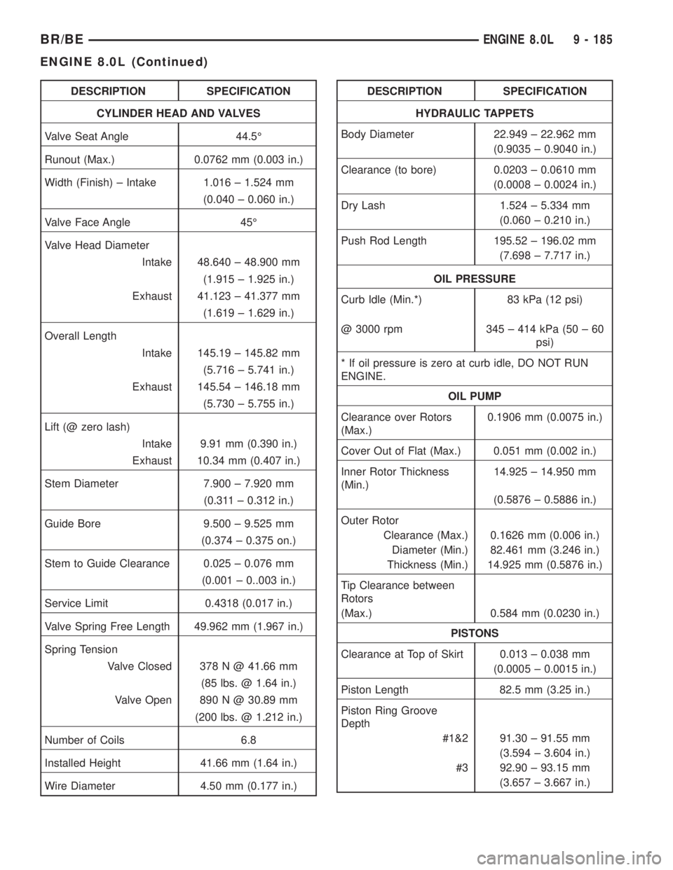
DESCRIPTION SPECIFICATION
CYLINDER HEAD AND VALVES
Valve Seat Angle 44.5É
Runout (Max.) 0.0762 mm (0.003 in.)
Width (Finish) ± Intake 1.016 ± 1.524 mm
(0.040 ± 0.060 in.)
Valve Face Angle 45É
Valve Head Diameter
Intake 48.640 ± 48.900 mm
(1.915 ± 1.925 in.)
Exhaust 41.123 ± 41.377 mm
(1.619 ± 1.629 in.)
Overall Length
Intake 145.19 ± 145.82 mm
(5.716 ± 5.741 in.)
Exhaust 145.54 ± 146.18 mm
(5.730 ± 5.755 in.)
Lift (@ zero lash)
Intake 9.91 mm (0.390 in.)
Exhaust 10.34 mm (0.407 in.)
Stem Diameter 7.900 ± 7.920 mm
(0.311 ± 0.312 in.)
Guide Bore 9.500 ± 9.525 mm
(0.374 ± 0.375 on.)
Stem to Guide Clearance 0.025 ± 0.076 mm
(0.001 ± 0..003 in.)
Service Limit 0.4318 (0.017 in.)
Valve Spring Free Length 49.962 mm (1.967 in.)
Spring Tension
Valve Closed 378 N @ 41.66 mm
(85 lbs. @ 1.64 in.)
Valve Open 890 N @ 30.89 mm
(200 lbs. @ 1.212 in.)
Number of Coils 6.8
Installed Height 41.66 mm (1.64 in.)
Wire Diameter 4.50 mm (0.177 in.)DESCRIPTION SPECIFICATION
HYDRAULIC TAPPETS
Body Diameter 22.949 ± 22.962 mm
(0.9035 ± 0.9040 in.)
Clearance (to bore) 0.0203 ± 0.0610 mm
(0.0008 ± 0.0024 in.)
Dry Lash 1.524 ± 5.334 mm
(0.060 ± 0.210 in.)
Push Rod Length 195.52 ± 196.02 mm
(7.698 ± 7.717 in.)
OIL PRESSURE
Curb Idle (Min.*) 83 kPa (12 psi)
@ 3000 rpm 345 ± 414 kPa (50 ± 60
psi)
* If oil pressure is zero at curb idle, DO NOT RUN
ENGINE.
OIL PUMP
Clearance over Rotors
(Max.)0.1906 mm (0.0075 in.)
Cover Out of Flat (Max.) 0.051 mm (0.002 in.)
Inner Rotor Thickness
(Min.)14.925 ± 14.950 mm
(0.5876 ± 0.5886 in.)
Outer Rotor
Clearance (Max.) 0.1626 mm (0.006 in.)
Diameter (Min.) 82.461 mm (3.246 in.)
Thickness (Min.) 14.925 mm (0.5876 in.)
Tip Clearance between
Rotors
(Max.) 0.584 mm (0.0230 in.)
PISTONS
Clearance at Top of Skirt 0.013 ± 0.038 mm
(0.0005 ± 0.0015 in.)
Piston Length 82.5 mm (3.25 in.)
Piston Ring Groove
Depth
#1&2 91.30 ± 91.55 mm
(3.594 ± 3.604 in.)
#3 92.90 ± 93.15 mm
(3.657 ± 3.667 in.)
BR/BEENGINE 8.0L 9 - 185
ENGINE 8.0L (Continued)
Page 1700 of 2889
case top surface and in the housing/adapter are tight
and in good condition.
Run a tap through the gear case bolt holes if the
threads need minor cleanup. Helicoil inserts can be
used to repair seriously damaged threaded holes if
necessary.
Be sure all case and housing/adapter sealing and
mating surfaces are free of burrs and nicks. This is
especially important as gaskets are not used in the
transmission. Minor nicks and scratches on the seal-
ing surfaces can be dressed off with a fine tooth file
or oil stone.
Replace the gear case or housing/adapter if cracked
or broken. Do not attempt to repair this type of dam-
age by welding or brazing.
Check condition of the countershaft fifth gear com-
ponents. This includes the shift lug and rail located
in the gear case and the rail bushings.
Inspect the gear and hub assembly. Minor burrs
can be cleaned up with an oil stone. However, the
gear and hub assembly should be replaced if the
teeth or splines are excessively worn, or damaged.
The synchro sleeve should also be replaced if worn or
damaged in any way. Do not reuse synchro struts
that are worn or springs that are collapsed or
severely distorted. Replace worn distorted synchro
parts to avoid shift problems after assembly and
installation.
The shift fork should be inspected for evidence of
wear and distortion. Check fit of the sleeve in the
fork to be sure the two parts fit and work smoothly.
Replace the fork if the roll pin holes are worn over-
size or damaged. Do not attempt to salvage a worn
fork. It will cause shift problems later on. Replace
shift fork roll pins if necessary or if doubt exists
about their condition.
The bearings should be examined carefully for
wear, roughness, flat spots, pitting or other damage.
Replace the bearings if necessary.
Inspect the blocker ring and clutch gear. replace
either part if worn or damaged in any way. Also be
sure replacement parts fit properly before proceeding
with assembly.
Examine the 1-2 synchro hub and sleeve for wear
or damage. Replace sleeve and hub if the splines are
worn, chipped or damaged.
Replace the synchro struts if worn, or chipped. Also
replace the springs if collapsed, distorted or broken.
Inspect the mainshaft geartrain components.
Check teeth on all gears, hubs, clutch gears, stop
rings and clutch rings. The teeth must be in good
condition and not worn, cracked or chipped. Replace
any component that exhibits wear or damage.
Examine the synchro stop rings, clutch rings and
clutch gears. Replace any part that exhibits wear,distortion or damage. Replace the clutch rings if the
friction material is burned, flaking off or worn.
Inspect all of the thrust washers and locating pins.
Replace the pins if bent or worn. Replace the wash-
ers if worn or the locating pin notches are distorted.
Check condition of the synchro struts and springs.
Replace these parts if worn, cracked or distorted.
ASSEMBLY
NOTE: Gaskets are not used in the NV4500 trans-
mission. Use MoparTSilicone Sealer or equivalent
on all gear case and extension housing sealing sur-
faces.
COUNTERSHAFT AND REVERSE IDLER GEAR
(1) Install countershaft front bearing cup in case
with Handle C-4171 and Installer 6061-1.
(2) Install front bearing on countershaft with
Installer C-4340 (Fig. 64).
(3) Lubricate countershaft front bearing cup and
cone with petroleum jelly.
(4) Position gear case on end with rear of case fac-
ing up (Fig. 65).
(5) Install countershaft in gear case (Fig. 65).
NOTE: Do not install rear countershaft bearing on
countershaft at this time.
Fig. 64 Countershaft Front Bearing
1 - FRONT BEARING
2 - INSTALLER C-4340
3 - COUNTERSHAFT
BR/BEMANUAL - NV4500 21 - 65
MANUAL - NV4500 (Continued)
Page 1744 of 2889
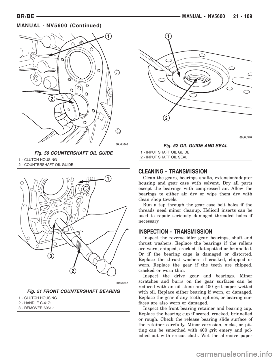
CLEANING - TRANSMISSION
Clean the gears, bearings shafts, extension/adapter
housing and gear case with solvent. Dry all parts
except the bearings with compressed air. Allow the
bearings to either air dry or wipe them dry with
clean shop towels.
Run a tap through the gear case bolt holes if the
threads need minor cleanup. Helicoil inserts can be
used to repair seriously damaged threaded holes if
necessary.
INSPECTION - TRANSMISSION
Inspect the reverse idler gear, bearings, shaft and
thrust washers. Replace the bearings if the rollers
are worn, chipped, cracked, flat-spotted or brinnelled.
Or if the bearing cage is damaged or distorted.
Replace the thrust washers if cracked, chipped or
worn. Replace the gear if the teeth are chipped,
cracked or worn thin.
Inspect the drive gear and bearings. Minor
scratches and burrs on the gear surfaces can be
reduced with an oil stone and 400 grit paper wetted
with oil. Replace either bearing if worn, or damaged.
Replace the gear if any teeth, splines, or bearing sur-
faces are also worn or damaged.
Inspect the front bearing retainer and bearing cup.
Replace the bearing cup if scored, cracked, brinnelled
or rough. Check the release bearing slide surface of
the retainer carefully. Minor corrosion, nicks, or pit-
ting can be smoothed with 400 grit emery and pol-
ished out with crocus cloth. Wet the abrasive paper
Fig. 50 COUNTERSHAFT OIL GUIDE
1 - CLUTCH HOUSING
2 - COUNTERSHAFT OIL GUIDE
Fig. 51 FRONT COUNTERSHAFT BEARING
1 - CLUTCH HOUSING
2 - HANDLE C-4171
3 - REMOVER 6061-1
Fig. 52 OIL GUIDE AND SEAL
1 - INPUT SHAFT OIL GUIDE
2 - INPUT SHAFT OIL SEAL
BR/BEMANUAL - NV5600 21 - 109
MANUAL - NV5600 (Continued)
Page 1745 of 2889
and crocus cloth with oil when smoothing/polishing.
Replace the retainer if worn or damaged in any way.
Do not reuse original retainer bolts. Install new bolts
during assembly.
Inspect the countershaft and bearings. Replace the
bearings if worn, rough, flat spotted or heat checked.
Check the countershaft gear teeth carefully. Small
nicks, scratches or burrs can be removed with an oil
stone and 400 grit paper wetted with oil. Replace the
shaft if any of the teeth are worn, cracked, broken or
severely chipped.
Be sure to check condition of the countershaft bear-
ing cups. Replace either bearings cup if worn, or
damaged.
Check condition of the mainshaft. Inspect all the
bearing surfaces, splines and threads. Also check con-
dition of the snap ring grooves in the hub area and
the speedometer drive gear teeth. Minor scratches or
burrs can be removed with an oil stone and polished
with crocus cloth. However, replace the shaft if any
surfaces exhibit considerable wear or damage.
Check condition of the gear case and extension or
adapter housing. Be sure the alignment dowels in the
case top surface and in the housing/adapter are tight
and in good condition.
Run a tap through the gear case bolt holes if the
threads need minor cleanup. Helicoil inserts can be
used to repair seriously damaged threaded holes if
necessary.
Be sure all case and housing/adapter sealing and
mating surfaces are free of burrs and nicks. This is
especially important as gaskets are not used in the
transmission. Minor nicks and scratches on the seal-
ing surfaces can be dressed off with a fine tooth file
or oil stone.
Replace the gear case or housing/adapter if cracked
or broken. Do not attempt to repair this type of dam-
age by welding or brazing.
Check condition of the countershaft fifth gear com-
ponents. This includes the shift lug and rail located
in the gear case and the rail bushings.
Inspect the gear and hub assembly. Minor burrs
can be cleaned up with an oil stone. However, the
gear and hub assembly should be replaced if the
teeth or splines are excessively worn, or damaged.
The synchro sleeve should also be replaced if worn or
damaged in any way. Do not reuse synchro struts
that are worn or springs that are collapsed or
severely distorted. Replace worn distorted synchro
parts to avoid shift problems after assembly and
installation.
The shift fork should be inspected for evidence of
wear and distortion. Check fit of the sleeve in the
fork to be sure the two parts fit and work smoothly.
Replace the fork if the roll pin holes are worn over-
size or damaged. Do not attempt to salvage a wornfork. It will cause shift problems later on. Replace
shift fork roll pins if necessary or if doubt exists
about their condition.
The bearings should be examined carefully for
wear, roughness, flat spots, pitting or other damage.
Replace the bearings if necessary.
Inspect the blocker ring and clutch gear. replace
either part if worn or damaged in any way. Also be
sure replacement parts fit properly before proceeding
with assembly.
Examine the 1-2 synchro hub and sleeve for wear
or damage. Replace sleeve and hub if the splines are
worn, chipped or damaged.
Replace the synchro struts if worn, or chipped. Also
replace the springs if collapsed, distorted or broken.
Inspect the mainshaft geartrain components.
Check teeth on all gears, hubs, clutch gears, stop
rings and clutch rings. The teeth must be in good
condition and not worn, cracked or chipped. Replace
any component that exhibits wear or damage.
Examine the synchro stop rings, clutch rings and
clutch gears. Replace any part that exhibits wear,
distortion or damage. Replace the clutch rings if the
friction material is burned, flaking off or worn.
Inspect all of the thrust washers and locating pins.
Replace the pins if bent or worn. Replace the wash-
ers if worn or the locating pin notches are distorted.
Check condition of the synchro struts and springs.
Replace these parts if worn, cracked or distorted.
ASSEMBLY
NOTE: Gaskets are not used in the transmission.
Use MoparTGasket Maker or equivalent on all gear
case and extension housing sealing surfaces.
OUTPUT SHAFT
(1) Place second gear on bench with the synchro
clutch ring up.
(2) Install second gear synchro inner blocker ring
onto second gear (Fig. 53).
(3) Install second gear synchro friction cone over
the blocker ring and onto second gear (Fig. 54).
(4) Install second gear synchro outer blocker ring
over the second gear synchro friction cone. Align one
of the lugs on the outer ring with a lug on the inner
ring (Fig. 55).
(5) Install 1-2 synchro assembly onto the second
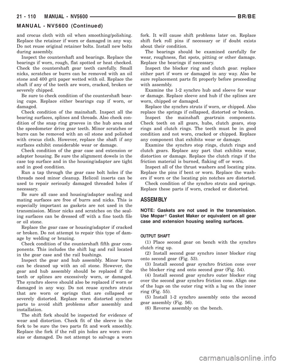
gear assembly (Fig. 56).
(6) Reverse assembly on the bench.
21 - 110 MANUAL - NV5600BR/BE
MANUAL - NV5600 (Continued)