headlamp DODGE RAM 2002 Service Owners Manual
[x] Cancel search | Manufacturer: DODGE, Model Year: 2002, Model line: RAM, Model: DODGE RAM 2002Pages: 2255, PDF Size: 62.07 MB
Page 1021 of 2255
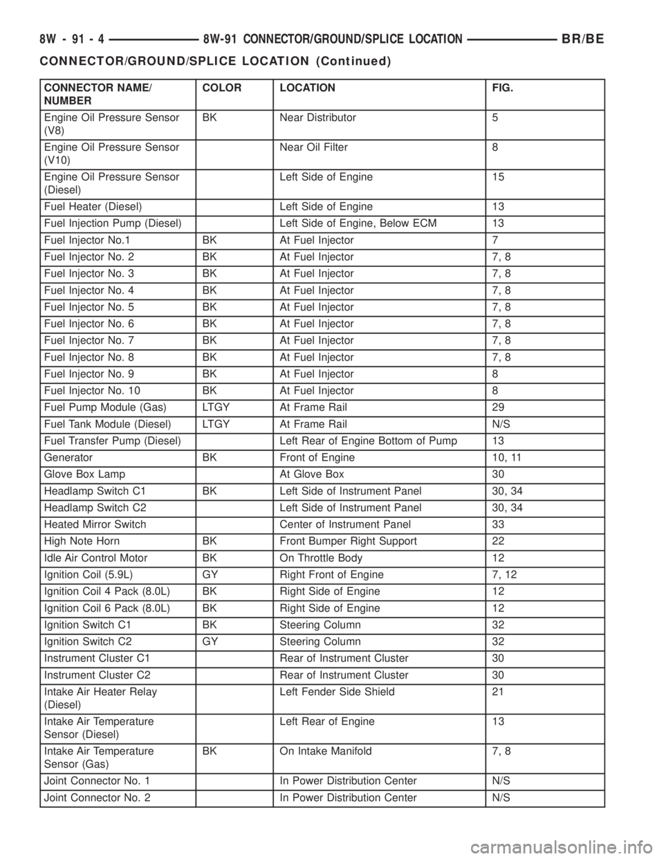
CONNECTOR NAME/
NUMBERCOLOR LOCATION FIG.
Engine Oil Pressure Sensor
(V8)BK Near Distributor 5
Engine Oil Pressure Sensor
(V10)Near Oil Filter 8
Engine Oil Pressure Sensor
(Diesel)Left Side of Engine 15
Fuel Heater (Diesel) Left Side of Engine 13
Fuel Injection Pump (Diesel) Left Side of Engine, Below ECM 13
Fuel Injector No.1 BK At Fuel Injector 7
Fuel Injector No. 2 BK At Fuel Injector 7, 8
Fuel Injector No. 3 BK At Fuel Injector 7, 8
Fuel Injector No. 4 BK At Fuel Injector 7, 8
Fuel Injector No. 5 BK At Fuel Injector 7, 8
Fuel Injector No. 6 BK At Fuel Injector 7, 8
Fuel Injector No. 7 BK At Fuel Injector 7, 8
Fuel Injector No. 8 BK At Fuel Injector 7, 8
Fuel Injector No. 9 BK At Fuel Injector 8
Fuel Injector No. 10 BK At Fuel Injector 8
Fuel Pump Module (Gas) LTGY At Frame Rail 29
Fuel Tank Module (Diesel) LTGY At Frame Rail N/S
Fuel Transfer Pump (Diesel) Left Rear of Engine Bottom of Pump 13
Generator BK Front of Engine 10, 11
Glove Box Lamp At Glove Box 30
Headlamp Switch C1 BK Left Side of Instrument Panel 30, 34
Headlamp Switch C2 Left Side of Instrument Panel 30, 34
Heated Mirror Switch Center of Instrument Panel 33
High Note Horn BK Front Bumper Right Support 22
Idle Air Control Motor BK On Throttle Body 12
Ignition Coil (5.9L) GY Right Front of Engine 7, 12
Ignition Coil 4 Pack (8.0L) BK Right Side of Engine 12
Ignition Coil 6 Pack (8.0L) BK Right Side of Engine 12
Ignition Switch C1 BK Steering Column 32
Ignition Switch C2 GY Steering Column 32
Instrument Cluster C1 Rear of Instrument Cluster 30
Instrument Cluster C2 Rear of Instrument Cluster 30
Intake Air Heater Relay
(Diesel)Left Fender Side Shield 21
Intake Air Temperature
Sensor (Diesel)Left Rear of Engine 13
Intake Air Temperature
Sensor (Gas)BK On Intake Manifold 7, 8
Joint Connector No. 1 In Power Distribution Center N/S
Joint Connector No. 2 In Power Distribution Center N/S
8W - 91 - 4 8W-91 CONNECTOR/GROUND/SPLICE LOCATIONBR/BE
CONNECTOR/GROUND/SPLICE LOCATION (Continued)
Page 1022 of 2255
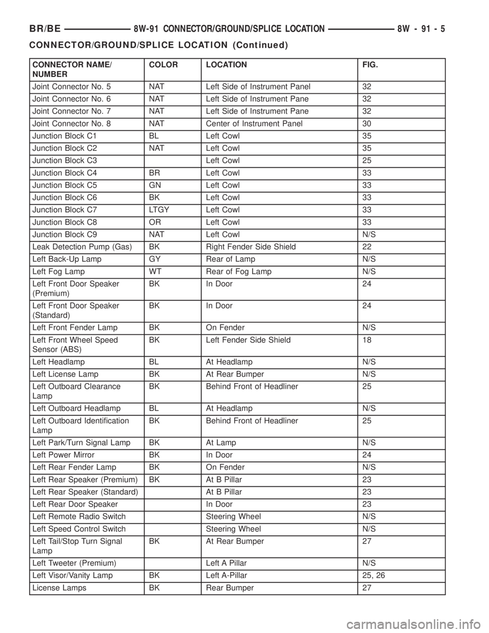
CONNECTOR NAME/
NUMBERCOLOR LOCATION FIG.
Joint Connector No. 5 NAT Left Side of Instrument Panel 32
Joint Connector No. 6 NAT Left Side of Instrument Pane 32
Joint Connector No. 7 NAT Left Side of Instrument Pane 32
Joint Connector No. 8 NAT Center of Instrument Panel 30
Junction Block C1 BL Left Cowl 35
Junction Block C2 NAT Left Cowl 35
Junction Block C3 Left Cowl 25
Junction Block C4 BR Left Cowl 33
Junction Block C5 GN Left Cowl 33
Junction Block C6 BK Left Cowl 33
Junction Block C7 LTGY Left Cowl 33
Junction Block C8 OR Left Cowl 33
Junction Block C9 NAT Left Cowl N/S
Leak Detection Pump (Gas) BK Right Fender Side Shield 22
Left Back-Up Lamp GY Rear of Lamp N/S
Left Fog Lamp WT Rear of Fog Lamp N/S
Left Front Door Speaker
(Premium)BK In Door 24
Left Front Door Speaker
(Standard)BK In Door 24
Left Front Fender Lamp BK On Fender N/S
Left Front Wheel Speed
Sensor (ABS)BK Left Fender Side Shield 18
Left Headlamp BL At Headlamp N/S
Left License Lamp BK At Rear Bumper N/S
Left Outboard Clearance
LampBK Behind Front of Headliner 25
Left Outboard Headlamp BL At Headlamp N/S
Left Outboard Identification
LampBK Behind Front of Headliner 25
Left Park/Turn Signal Lamp BK At Lamp N/S
Left Power Mirror BK In Door 24
Left Rear Fender Lamp BK On Fender N/S
Left Rear Speaker (Premium) BK At B Pillar 23
Left Rear Speaker (Standard) At B Pillar 23
Left Rear Door Speaker In Door 23
Left Remote Radio Switch Steering Wheel N/S
Left Speed Control Switch Steering Wheel N/S
Left Tail/Stop Turn Signal
LampBK At Rear Bumper 27
Left Tweeter (Premium) Left A Pillar N/S
Left Visor/Vanity Lamp BK Left A-Pillar 25, 26
License Lamps BK Rear Bumper 27
BR/BE8W-91 CONNECTOR/GROUND/SPLICE LOCATION 8W - 91 - 5
CONNECTOR/GROUND/SPLICE LOCATION (Continued)
Page 1024 of 2255
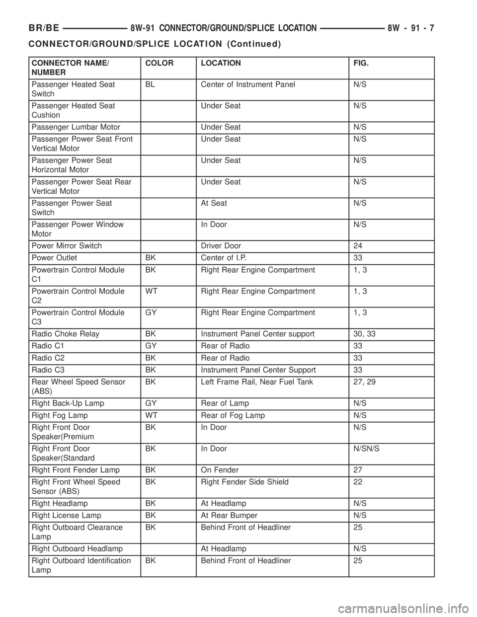
CONNECTOR NAME/
NUMBERCOLOR LOCATION FIG.
Passenger Heated Seat
SwitchBL Center of Instrument Panel N/S
Passenger Heated Seat
CushionUnder Seat N/S
Passenger Lumbar Motor Under Seat N/S
Passenger Power Seat Front
Vertical MotorUnder Seat N/S
Passenger Power Seat
Horizontal MotorUnder Seat N/S
Passenger Power Seat Rear
Vertical MotorUnder Seat N/S
Passenger Power Seat
SwitchAt Seat N/S
Passenger Power Window
MotorIn Door N/S
Power Mirror Switch Driver Door 24
Power Outlet BK Center of I.P. 33
Powertrain Control Module
C1BK Right Rear Engine Compartment 1, 3
Powertrain Control Module
C2WT Right Rear Engine Compartment 1, 3
Powertrain Control Module
C3GY Right Rear Engine Compartment 1, 3
Radio Choke Relay BK Instrument Panel Center support 30, 33
Radio C1 GY Rear of Radio 33
Radio C2 BK Rear of Radio 33
Radio C3 BK Instrument Panel Center Support 33
Rear Wheel Speed Sensor
(ABS)BK Left Frame Rail, Near Fuel Tank 27, 29
Right Back-Up Lamp GY Rear of Lamp N/S
Right Fog Lamp WT Rear of Fog Lamp N/S
Right Front Door
Speaker(PremiumBK In Door N/S
Right Front Door
Speaker(StandardBK In Door N/SN/S
Right Front Fender Lamp BK On Fender 27
Right Front Wheel Speed
Sensor (ABS)BK Right Fender Side Shield 22
Right Headlamp BK At Headlamp N/S
Right License Lamp BK At Rear Bumper N/S
Right Outboard Clearance
LampBK Behind Front of Headliner 25
Right Outboard Headlamp At Headlamp N/S
Right Outboard Identification
LampBK Behind Front of Headliner 25
BR/BE8W-91 CONNECTOR/GROUND/SPLICE LOCATION 8W - 91 - 7
CONNECTOR/GROUND/SPLICE LOCATION (Continued)
Page 1026 of 2255
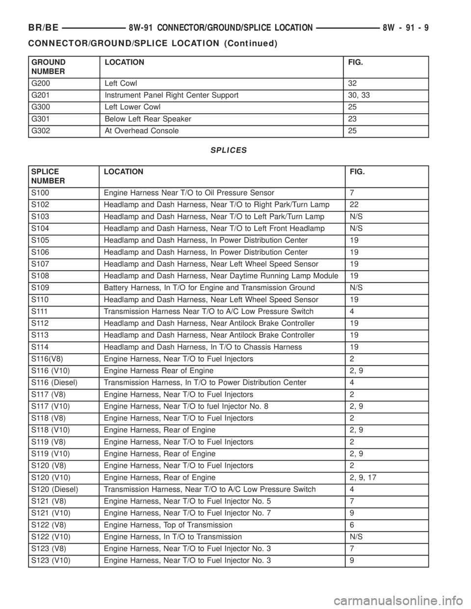
GROUND
NUMBERLOCATION FIG.
G200 Left Cowl 32
G201 Instrument Panel Right Center Support 30, 33
G300 Left Lower Cowl 25
G301 Below Left Rear Speaker 23
G302 At Overhead Console 25
SPLICES
SPLICE
NUMBERLOCATION FIG.
S100 Engine Harness Near T/O to Oil Pressure Sensor 7
S102 Headlamp and Dash Harness, Near T/O to Right Park/Turn Lamp 22
S103 Headlamp and Dash Harness, Near T/O to Left Park/Turn Lamp N/S
S104 Headlamp and Dash Harness, Near T/O to Left Front Headlamp N/S
S105 Headlamp and Dash Harness, In Power Distribution Center 19
S106 Headlamp and Dash Harness, In Power Distribution Center 19
S107 Headlamp and Dash Harness, Near Left Wheel Speed Sensor 19
S108 Headlamp and Dash Harness, Near Daytime Running Lamp Module 19
S109 Battery Harness, In T/O for Engine and Transmission Ground N/S
S110 Headlamp and Dash Harness, Near Left Wheel Speed Sensor 19
S111 Transmission Harness Near T/O to A/C Low Pressure Switch 4
S112 Headlamp and Dash Harness, Near Antilock Brake Controller 19
S113 Headlamp and Dash Harness, Near Antilock Brake Controller 19
S114 Headlamp and Dash Harness, In T/O to Chassis Harness 19
S116(V8) Engine Harness, Near T/O to Fuel Injectors 2
S116 (V10) Engine Harness Rear of Engine 2, 9
S116 (Diesel) Transmission Harness, In T/O to Power Distribution Center 4
S117 (V8) Engine Harness, Near T/O to Fuel Injectors 2
S117 (V10) Engine Harness, Near T/O to fuel Injector No. 8 2, 9
S118 (V8) Engine Harness, Near T/O to Fuel Injectors 2
S118 (V10) Engine Harness, Rear of Engine 2, 9
S119 (V8) Engine Harness, Near T/O to Fuel Injectors 2
S119 (V10) Engine Harness, Rear of Engine 2, 9
S120 (V8) Engine Harness, Near T/O to Fuel Injectors 2
S120 (V10) Engine Harness, Rear of Engine 2, 9, 17
S120 (Diesel) Transmission Harness, Near T/O to A/C Low Pressure Switch 4
S121 (V8) Engine Harness, Near T/O to Fuel Injector No. 5 7
S121 (V10) Engine Harness, Near T/O to Fuel Injector No. 7 9
S122 (V8) Engine Harness, Top of Transmission 6
S122 (V10) Engine Harness, In T/O to Transmission N/S
S123 (V8) Engine Harness, Near T/O to Fuel Injector No. 3 7
S123 (V10) Engine Harness, Near T/O to Fuel Injector No. 3 9
BR/BE8W-91 CONNECTOR/GROUND/SPLICE LOCATION 8W - 91 - 9
CONNECTOR/GROUND/SPLICE LOCATION (Continued)
Page 1027 of 2255
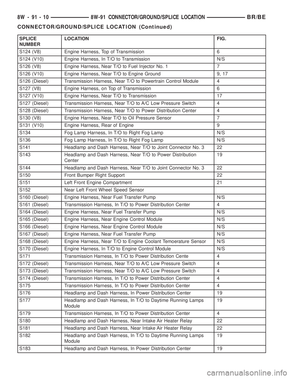
SPLICE
NUMBERLOCATION FIG.
S124 (V8) Engine Harness, Top of Transmission 6
S124 (V10) Engine Harness, In T/O to Transmission N/S
S126 (V8) Engine Harness, Near T/O to Fuel Injector No. 1 7
S126 (V10) Engine Harness, Near T/O to Engine Ground 9, 17
S126 (Diesel) Transmission Harness, Near T/O to Powertrain Control Module 4
S127 (V8) Engine Harness, on Top of Transmission 6
S127 (V10) Engine Harness, Near T/O to Transmission 17
S127 (Diesel) Transmission Harness, Near T/O to A/C Low Pressure Switch 4
S128 (Diesel) Transmission Harness, Near T/O to Power Distribution Center 4
S130 (V8) Engine Harness, Near T/O to Oil Pressure Sensor 7
S131 (V10) Engine Harness, Rear of Engine 9
S134 Fog Lamp Harness, In T/O to Right Fog Lamp N/S
S136 Fog Lamp Harness, In T/O to Right Fog Lamp N/S
S141 Headlamp and Dash Harness, Near T/O to Joint Connector No. 3 22
S143 Headlamp and Dash Harness, Near T/O to Power Distribution
Center19
S144 Headlamp and Dash Harness, Near T/O to Joint Connector No. 3 22
S150 Front Bumper Right Support 22
S151 Left Front Engine Compartment 21
S152 Near Left Front Wheel Speed Sensor
S160 (Diesel) Engine Harness, Near Fuel Transfer Pump N/S
S161 (Diesel) Transmission Harness, In T/O to Power Distribution Center 4
S164 (Diesel) Engine Harness, Near Fuel Transfer Pump N/S
S165 (Diesel) Engine Harness, Near Engine Control Module N/S
S166 (Diesel) Engine Harness, Near Engine Control Module N/S
S167 (Diesel) Engine Harness, Near Fuel Transfer Pump N/S
S168 (Diesel) Engine Harness, Near T/O to Engine Coolant Temoerature Sensor N/S
S170 (Diesel) Engine Harness, In T/O to Engine Control Module N/S
S171 Transmission Harness, In T/O to Power Distribution Cente 4
S172 (Diesel) Transmission Harness, Near T/O to A/C Low Pressure Switch 4
S173 (Diesel) Transmission Harness, Near T/O to A/C Low Pressure Switch 4
S174 (Diesel) Transmission Harness, In T/O to Power Distribution Center 4
S175 Transmission Harness, In T/O to Power Distribution Center 4
S176 Headlamp and Dash Harness, In Power Distribution Center 19
S177 Headlamp and Dash Harness, In T/O to Daytime Running Lamps
Module19
S179 Transmission Harness, In T/O to Power Distribution Center 4
S180 Headlamp and Dash Harness, Near Intake Air Heater Relay 22
S181 Headlamp and Dash Harness, Near Intake Air Heater Relay 22
S182 Headlamp and Dash Harness, In T/O to Daytime Running Lamps
Module19
S183 Headlamp and Dash Harness, In Power Distribution Center 19
8W - 91 - 10 8W-91 CONNECTOR/GROUND/SPLICE LOCATIONBR/BE
CONNECTOR/GROUND/SPLICE LOCATION (Continued)
Page 1060 of 2255
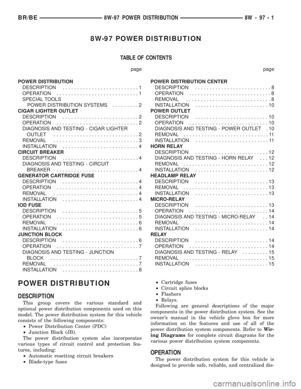
8W-97 POWER DISTRIBUTION
TABLE OF CONTENTS
page page
POWER DISTRIBUTION
DESCRIPTION..........................1
OPERATION............................1
SPECIAL TOOLS
POWER DISTRIBUTION SYSTEMS.........2
CIGAR LIGHTER OUTLET
DESCRIPTION..........................2
OPERATION............................2
DIAGNOSIS AND TESTING - CIGAR LIGHTER
OUTLET.............................2
REMOVAL.............................3
INSTALLATION..........................4
CIRCUIT BREAKER
DESCRIPTION..........................4
DIAGNOSIS AND TESTING - CIRCUIT
BREAKER............................4
GENERATOR CARTRIDGE FUSE
DESCRIPTION..........................4
OPERATION............................4
REMOVAL.............................4
INSTALLATION..........................4
IOD FUSE
DESCRIPTION..........................5
OPERATION............................5
REMOVAL.............................6
INSTALLATION..........................6
JUNCTION BLOCK
DESCRIPTION..........................6
OPERATION............................7
DIAGNOSIS AND TESTING - JUNCTION
BLOCK..............................7
REMOVAL.............................7
INSTALLATION..........................8POWER DISTRIBUTION CENTER
DESCRIPTION..........................8
OPERATION............................8
REMOVAL.............................8
INSTALLATION.........................10
POWER OUTLET
DESCRIPTION.........................10
OPERATION...........................10
DIAGNOSIS AND TESTING - POWER OUTLET . 10
REMOVAL.............................11
INSTALLATION.........................11
HORN RELAY
DESCRIPTION.........................12
DIAGNOSIS AND TESTING - HORN RELAY . . . 12
REMOVAL.............................12
INSTALLATION.........................12
HEADLAMP RELAY
DESCRIPTION.........................13
REMOVAL.............................13
INSTALLATION.........................13
MICRO-RELAY
DESCRIPTION.........................13
OPERATION...........................14
DIAGNOSIS AND TESTING - MICRO-RELAY . . 14
REMOVAL.............................14
INSTALLATION.........................14
RELAY
DESCRIPTION.........................14
OPERATION...........................14
DIAGNOSIS AND TESTING - RELAY.........15
REMOVAL.............................15
INSTALLATION.........................15
POWER DISTRIBUTION
DESCRIPTION
This group covers the various standard and
optional power distribution components used on this
model. The power distribution system for this vehicle
consists of the following components:
²Power Distribution Center (PDC)
²Junction Block (JB).
The power distribution system also incorporates
various types of circuit control and protection fea-
tures, including:
²Automatic resetting circuit breakers
²Blade-type fuses²Cartridge fuses
²Circuit splice blocks
²Flashers
²Relays.
Following are general descriptions of the major
components in the power distribution system. See the
owner's manual in the vehicle glove box for more
information on the features and use of all of the
power distribution system components. Refer toWir-
ing Diagramsfor complete circuit diagrams for the
various power distribution system components.
OPERATION
The power distribution system for this vehicle is
designed to provide safe, reliable, and centralized dis-
BR/BE8W-97 POWER DISTRIBUTION 8W - 97 - 1
Page 1067 of 2255
(11) Remove the junction block from under the
instrument panel.
INSTALLATION
NOTE: If the Junction Block (JB) is being replaced
with a new unit, be certain to transfer each of the
fuses, circuit breakers and relays from the faulty JB
to the proper cavities of the replacement JB. Refer
to Junction Block in the index of this service man-
ual for the location of complete circuit diagrams
and cavity assignments for the JB.
(1) Position the junction block under the instru-
ment panel.
(2) Connect all of the wire harness connectors on
the Junction Block (JB) connector receptacles.
(3) Install the two junction block retaining screws.
(4) Install the electrical ground connections,
located behind park brake mounting location.
(5) Install the parking brake switch connector,
release linkage and retaining fasteners.
(6) Reposition drivers side carpet.
(7) Install the lower knee blocker on the instru-
ment panel.
(8) Install the hood release handle retaining
screws.
(9) Install the steering column cover.
(10) Install the fuse access bezel on the instrument
panel.
(11) Connect the battery negative cable.
POWER DISTRIBUTION
CENTER
DESCRIPTION
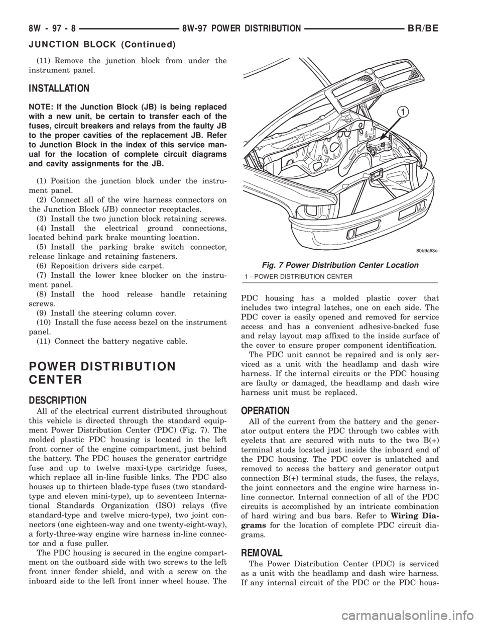
All of the electrical current distributed throughout
this vehicle is directed through the standard equip-
ment Power Distribution Center (PDC) (Fig. 7). The
molded plastic PDC housing is located in the left
front corner of the engine compartment, just behind
the battery. The PDC houses the generator cartridge
fuse and up to twelve maxi-type cartridge fuses,
which replace all in-line fusible links. The PDC also
houses up to thirteen blade-type fuses (two standard-
type and eleven mini-type), up to seventeen Interna-
tional Standards Organization (ISO) relays (five
standard-type and twelve micro-type), two joint con-
nectors (one eighteen-way and one twenty-eight-way),
a forty-three-way engine wire harness in-line connec-
tor and a fuse puller.
The PDC housing is secured in the engine compart-
ment on the outboard side with two screws to the left
front inner fender shield, and with a screw on the
inboard side to the left front inner wheel house. ThePDC housing has a molded plastic cover that
includes two integral latches, one on each side. The
PDC cover is easily opened and removed for service
access and has a convenient adhesive-backed fuse
and relay layout map affixed to the inside surface of
the cover to ensure proper component identification.
The PDC unit cannot be repaired and is only ser-
viced as a unit with the headlamp and dash wire
harness. If the internal circuits or the PDC housing
are faulty or damaged, the headlamp and dash wire
harness unit must be replaced.OPERATION
All of the current from the battery and the gener-
ator output enters the PDC through two cables with
eyelets that are secured with nuts to the two B(+)
terminal studs located just inside the inboard end of
the PDC housing. The PDC cover is unlatched and
removed to access the battery and generator output
connection B(+) terminal studs, the fuses, the relays,
the joint connectors and the engine wire harness in-
line connector. Internal connection of all of the PDC
circuits is accomplished by an intricate combination
of hard wiring and bus bars. Refer toWiring Dia-
gramsfor the location of complete PDC circuit dia-
grams.
REMOVAL
The Power Distribution Center (PDC) is serviced
as a unit with the headlamp and dash wire harness.
If any internal circuit of the PDC or the PDC hous-
Fig. 7 Power Distribution Center Location
1 - POWER DISTRIBUTION CENTER
8W - 97 - 8 8W-97 POWER DISTRIBUTIONBR/BE
JUNCTION BLOCK (Continued)
Page 1068 of 2255
ing is faulty or damaged, the entire PDC and head-
lamp and dash wire harness unit must be replaced.
(1) Disconnect and isolate the battery negative
cable.
(2) Disconnect each of the headlamp and dash wire
harness connectors. Refer toConnector Locations
in Wiring for the location of more information on the
headlamp and dash wire harness connector locations.
(3) Remove all of the fasteners that secure each of
the headlamp and dash wire harness ground eyelets
to the vehicle body and chassis components. Refer to
Connector Locationsin Wiring for the location of
more information on the ground eyelet locations.
(4) Disengage each of the retainers that secure the
headlamp and dash wire harness to the vehicle body
and chassis components. Refer toConnector Loca-
tionsin Wiring for the location of more information
on the headlamp and dash wire harness retainer
locations.
(5) Unlatch and remove the cover from the PDC.
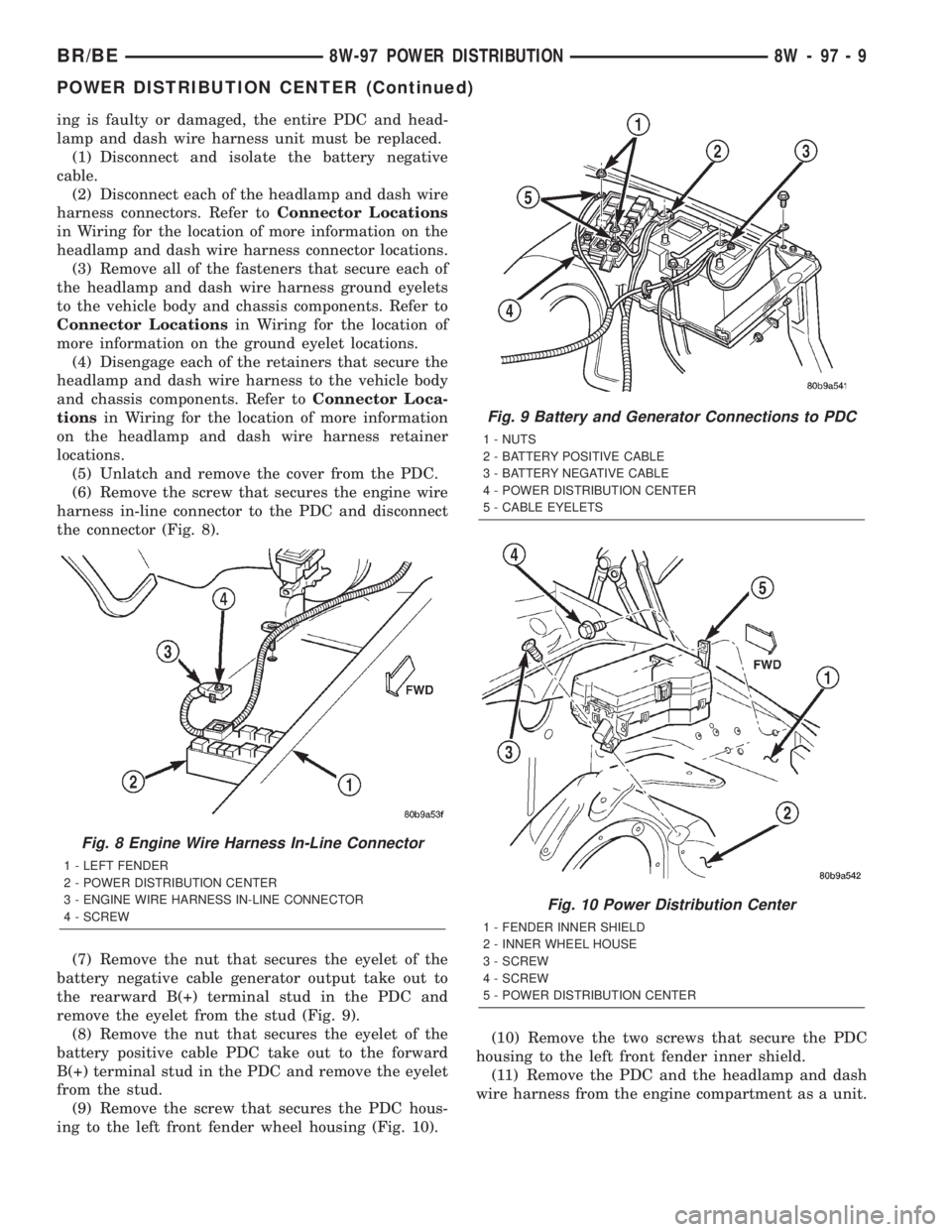
(6) Remove the screw that secures the engine wire
harness in-line connector to the PDC and disconnect
the connector (Fig. 8).
(7) Remove the nut that secures the eyelet of the
battery negative cable generator output take out to
the rearward B(+) terminal stud in the PDC and
remove the eyelet from the stud (Fig. 9).
(8) Remove the nut that secures the eyelet of the
battery positive cable PDC take out to the forward
B(+) terminal stud in the PDC and remove the eyelet
from the stud.
(9) Remove the screw that secures the PDC hous-
ing to the left front fender wheel housing (Fig. 10).(10) Remove the two screws that secure the PDC
housing to the left front fender inner shield.
(11) Remove the PDC and the headlamp and dash
wire harness from the engine compartment as a unit.
Fig. 8 Engine Wire Harness In-Line Connector
1 - LEFT FENDER
2 - POWER DISTRIBUTION CENTER
3 - ENGINE WIRE HARNESS IN-LINE CONNECTOR
4 - SCREW
Fig. 9 Battery and Generator Connections to PDC
1 - NUTS
2 - BATTERY POSITIVE CABLE
3 - BATTERY NEGATIVE CABLE
4 - POWER DISTRIBUTION CENTER
5 - CABLE EYELETS
Fig. 10 Power Distribution Center
1 - FENDER INNER SHIELD
2 - INNER WHEEL HOUSE
3 - SCREW
4 - SCREW
5 - POWER DISTRIBUTION CENTER
BR/BE8W-97 POWER DISTRIBUTION 8W - 97 - 9
POWER DISTRIBUTION CENTER (Continued)
Page 1069 of 2255
INSTALLATION
The Power Distribution Center (PDC) is serviced
as a unit with the headlamp and dash wire harness.
If any internal circuit of the PDC or the PDC hous-
ing is faulty or damaged, the entire PDC and head-
lamp and dash wire harness unit must be replaced.
NOTE: If the PDC is being replaced with a new unit,
be certain to transfer each of the blade-type fuses,
cartridge fuses and relays from the faulty PDC to
the proper cavities of the replacement PDC. Refer
to Power Distribution in the index of this service
manual for the location of complete PDC circuit dia-
grams and cavity assignments.
(1) Position the PDC and the headlamp and dash
wire harness unit in the engine compartment.
(2) Install and tighten the two screws that secure
the PDC housing to the left front fender inner shield.
Tighten the screws to 8.4 N´m (75 in. lbs.).
(3) Install and tighten the screw that secures the
PDC housing to the left front fender wheel housing.
Tighten the screw to 2.2 N´m (20 in. lbs.).
(4) Install the eyelet of the battery positive cable
PDC take out onto the forward B(+) terminal stud in
the PDC.
(5) Install and tighten the nut that secures the
eyelet of the battery positive cable PDC take out to
the forward B(+) terminal stud in the PDC. Tighten
the nut to 8.4 N´m (75 in. lbs.).
(6) Install the eyelet of the battery negative cable
generator output take out onto the rearward B(+) ter-
minal stud in the PDC.
(7) Install and tighten the nut that secures the
eyelet of the battery negative cable generator output
take out to the rearward B(+) terminal stud in the
PDC. Tighten the nut to 75 in. lbs.
(8) Reconnect the engine wire harness in-line con-
nector to the PDC.
(9) Install and tighten the screw that secures the
engine wire harness in-line connector to the PDC.
Tighten the screw until a distinct audible click is
heard.
(10) Install and latch the cover onto the PDC.
(11) Engage each of the retainers that secure the
headlamp and dash wire harness to the vehicle body
and chassis components. Refer toConnector Loca-
tionsin Wiring for the location of more information
on the headlamp and dash wire harness retainer
locations.
(12) Install all of the fasteners that secure each of
the headlamp and dash wire harness ground eyelets
to the vehicle body and chassis components. Refer to
Connector Locationsin Wiring for the location of
more information on the ground eyelet locations.(13) Reconnect each of the headlamp and dash
wire harness connectors. Refer toConnector Loca-
tionsin Wiring for the location of more information
on the headlamp and dash wire harness connector
locations.
(14) Reconnect the battery negative cable.
POWER OUTLET
DESCRIPTION
Two power outlets are installed in the vehicle. One
in the instrument panel next to the cigar lighter and
the other in the right rear quarter trim panel. The
power outlet bases are secured by a snap fit within
the instrument panel or trim panel. A plastic protec-
tive cap snaps into the power outlet base when the
power outlet is not being used, and hangs from the
power outlet base mount by an integral bail strap
while the power outlet is in use.
The power outlet receptacle unit and the accessory
power outlet protective cap are available for service.
The power outlet receptacle cannot be repaired and,
if faulty or damaged, it must be replaced.
OPERATION
The power outlet base or receptacle shell is con-
nected to ground, and an insulated contact in the
bottom of the shell is connected to battery current.
The power outlet receives battery voltage from a fuse
in the Junction Block at all times.
While the power outlet is very similar to a cigar
lighter base unit, it does not include the two small
spring-clip retainers inside the bottom of the recepta-
cle shell that are used to secure the cigar lighter
heating element to the insulated contact.
DIAGNOSIS AND TESTING - POWER OUTLET
For complete circuit diagrams, refer toPower
Outletin Wiring Diagrams.
(1) Check the fused B(+) fuse in the junction block.
If OK, go to Step 2. If not OK, repair the shorted cir-
cuit or component as required and replace the faulty
fuse.
(2) Check for battery voltage at the fused B(+) fuse
in the junction block. If OK, go to Step 3. If not OK,
repair the open fused B(+) circuit to the battery as
required.
(3) Remove the plastic protective cap from the
power outlet receptacle. Check for continuity between
the inside circumference of the power outlet recepta-
cle and a good ground. There should be continuity. If
OK, go to Step 4. If not OK, go to Step 5.
(4) Check for battery voltage at the insulated con-
tact located at the back of the power outlet recepta-
cle. If not OK, go to Step 5.
8W - 97 - 10 8W-97 POWER DISTRIBUTIONBR/BE
POWER DISTRIBUTION CENTER (Continued)
Page 1071 of 2255
(4) Press firmly on the cigar lighter or power out-
let receptacle base until the retaining bosses of the
mount are fully engaged in their receptacles.
(5) Install the cigar lighter knob and element into
the cigar lighter receptacle base, or the protective cap
into the power outlet receptacle base.
(6) Reconnect the battery negative cable.
HORN RELAY
DESCRIPTION
The horn relay is a International Standards Orga-
nization (ISO) micro-relay. The terminal designations
and functions are the same as a conventional ISO
relay. However, the micro-relay terminal orientation
(or footprint) is different, current capacity is lower,
and the relay case dimensions are smaller than those
of the conventional ISO relay.
The horn relay is a electromechanical device that
switches battery current to the horn when the horn
switch or when the high-line or premium Central
Timer Module (CTM) grounds the relay coil. See
Horn Relay in the Diagnosis and Testing section of
this group for more information.
The horn relay is located in the Power Distribution
Center (PDC), in the engine compartment. Refer to
the PDC label for relay identification and location.
If a problem is encountered with a continuously
sounding horn, it can usually be quickly resolved by
removing the horn relay from the PDC until further
diagnosis is completed.
The horn relay cannot be repaired and, if faulty or
damaged, it must be replaced.
DIAGNOSIS AND TESTING - HORN RELAY
The headlamp (or security) relay and the horn
relay are located in the Power Distribution Center
(PDC) in the engine compartment. Each of these
relays can be tested as described in the following pro-
cedure, however the circuits they are used in do vary.
To test the relay circuits, refer to the circuit descrip-
tions and diagrams in Wiring Diagrams.
WARNING: ON VEHICLES EQUIPPED WITH AIR-
BAGS, REFER TO THE RESTRAINTS SECTION OF
THE SERVICE MANUAL BEFORE ATTEMPTING ANY
STEERING WHEEL, STEERING COLUMN, OR
INSTRUMENT PANEL COMPONENT DIAGNOSIS OR
SERVICE. FAILURE TO TAKE THE PROPER PRE-
CAUTIONS COULD RESULT IN ACCIDENTAL AIR-
BAG DEPLOYMENT AND POSSIBLE PERSONAL
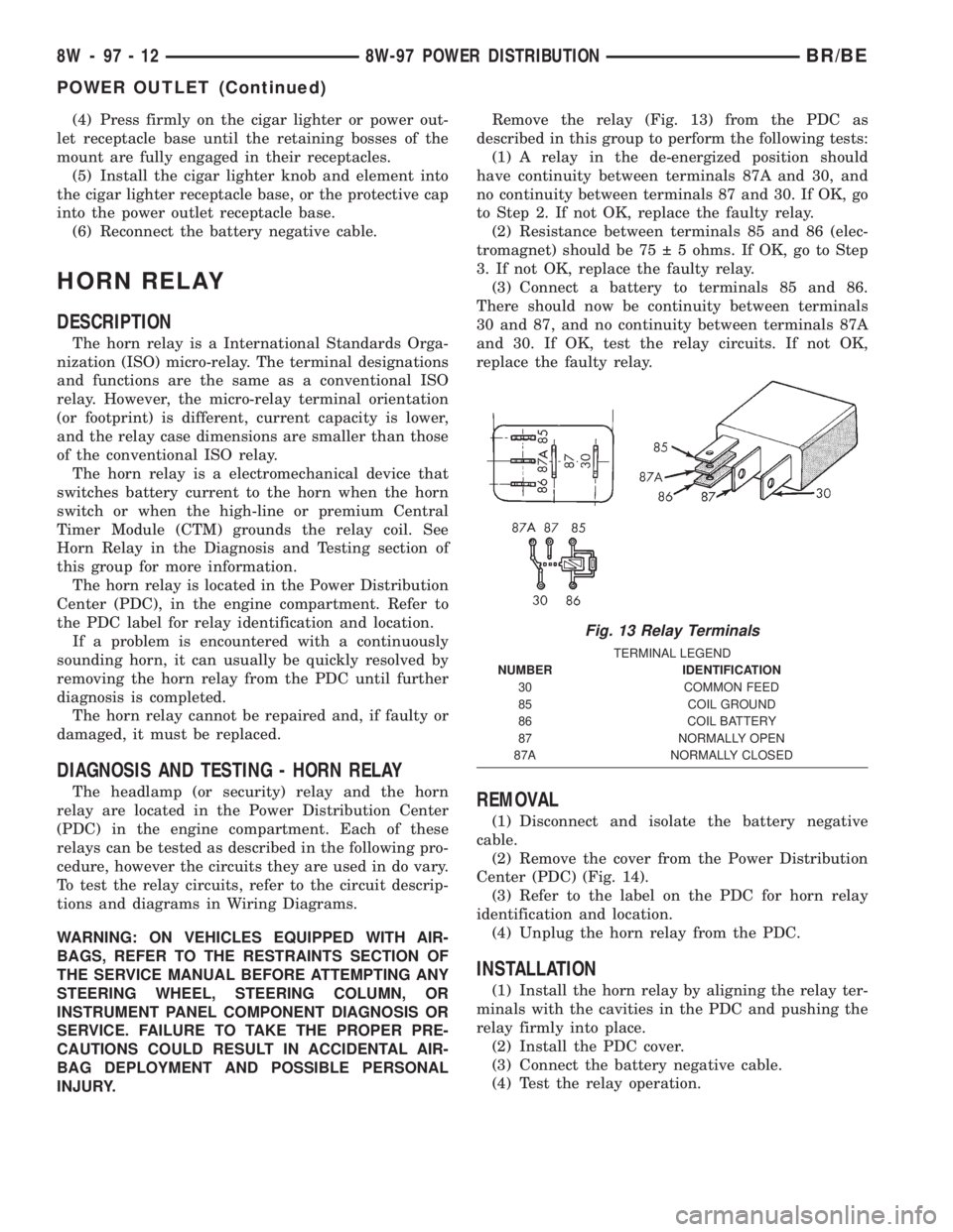
INJURY.Remove the relay (Fig. 13) from the PDC as
described in this group to perform the following tests:
(1) A relay in the de-energized position should
have continuity between terminals 87A and 30, and
no continuity between terminals 87 and 30. If OK, go
to Step 2. If not OK, replace the faulty relay.
(2) Resistance between terminals 85 and 86 (elec-
tromagnet) should be 75 5 ohms. If OK, go to Step
3. If not OK, replace the faulty relay.
(3) Connect a battery to terminals 85 and 86.
There should now be continuity between terminals
30 and 87, and no continuity between terminals 87A
and 30. If OK, test the relay circuits. If not OK,
replace the faulty relay.REMOVAL
(1) Disconnect and isolate the battery negative
cable.
(2) Remove the cover from the Power Distribution
Center (PDC) (Fig. 14).
(3) Refer to the label on the PDC for horn relay
identification and location.
(4) Unplug the horn relay from the PDC.
INSTALLATION
(1) Install the horn relay by aligning the relay ter-
minals with the cavities in the PDC and pushing the
relay firmly into place.
(2) Install the PDC cover.
(3) Connect the battery negative cable.
(4) Test the relay operation.
Fig. 13 Relay Terminals
TERMINAL LEGEND
NUMBER IDENTIFICATION
30 COMMON FEED
85 COIL GROUND
86 COIL BATTERY
87 NORMALLY OPEN
87A NORMALLY CLOSED
8W - 97 - 12 8W-97 POWER DISTRIBUTIONBR/BE
POWER OUTLET (Continued)