auxiliary battery DODGE RAM 2002 Service Repair Manual
[x] Cancel search | Manufacturer: DODGE, Model Year: 2002, Model line: RAM, Model: DODGE RAM 2002Pages: 2255, PDF Size: 62.07 MB
Page 20 of 2255
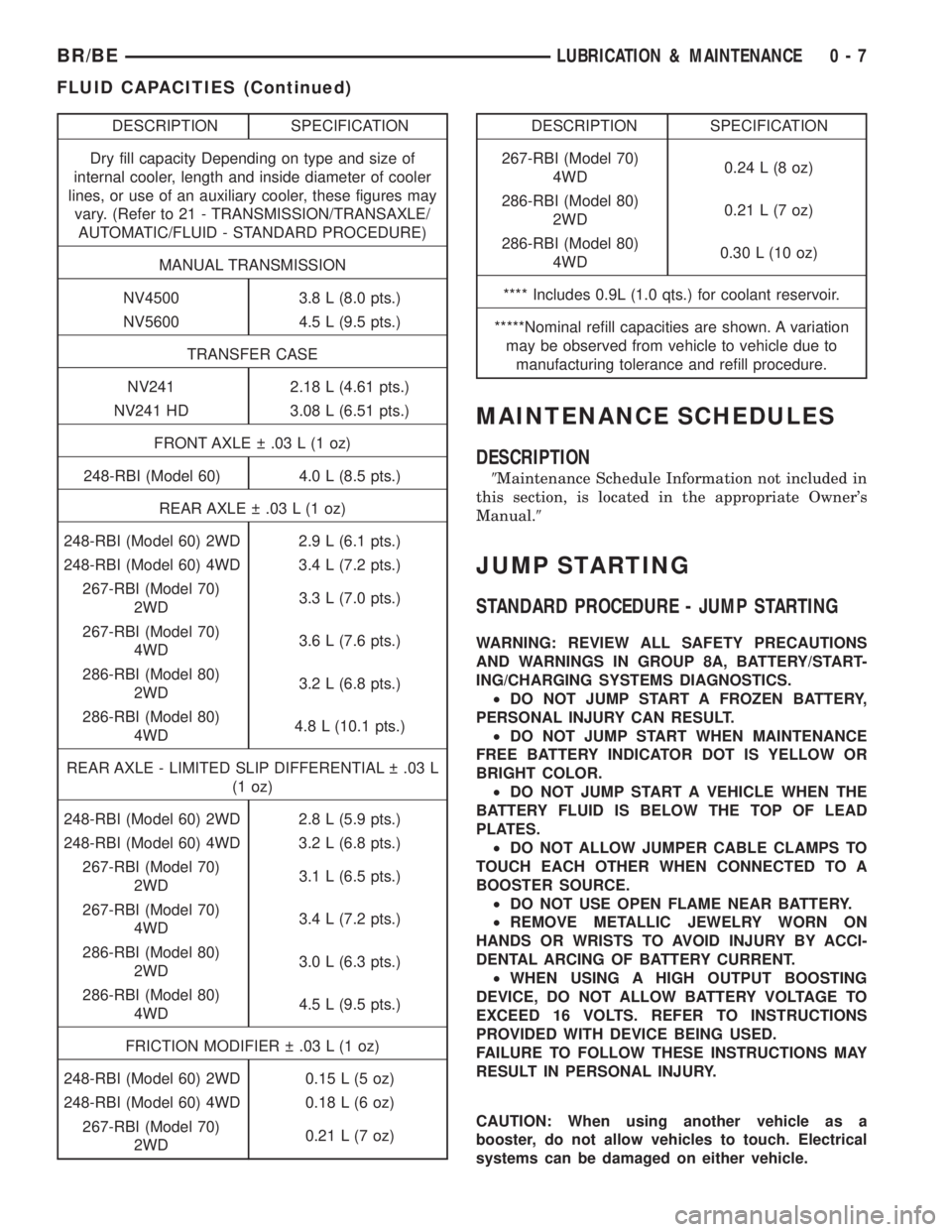
DESCRIPTION SPECIFICATION
Dry fill capacity Depending on type and size of
internal cooler, length and inside diameter of cooler
lines, or use of an auxiliary cooler, these figures may
vary. (Refer to 21 - TRANSMISSION/TRANSAXLE/
AUTOMATIC/FLUID - STANDARD PROCEDURE)
MANUAL TRANSMISSION
NV4500 3.8 L (8.0 pts.)
NV5600 4.5 L (9.5 pts.)
TRANSFER CASE
NV241 2.18 L (4.61 pts.)
NV241 HD 3.08 L (6.51 pts.)
FRONT AXLE .03 L (1 oz)
248-RBI (Model 60) 4.0 L (8.5 pts.)
REAR AXLE .03 L (1 oz)
248-RBI (Model 60) 2WD 2.9 L (6.1 pts.)
248-RBI (Model 60) 4WD 3.4 L (7.2 pts.)
267-RBI (Model 70)
2WD3.3 L (7.0 pts.)
267-RBI (Model 70)
4WD3.6 L (7.6 pts.)
286-RBI (Model 80)
2WD3.2 L (6.8 pts.)
286-RBI (Model 80)
4WD4.8 L (10.1 pts.)
REAR AXLE - LIMITED SLIP DIFFERENTIAL .03 L
(1 oz)
248-RBI (Model 60) 2WD 2.8 L (5.9 pts.)
248-RBI (Model 60) 4WD 3.2 L (6.8 pts.)
267-RBI (Model 70)
2WD3.1 L (6.5 pts.)
267-RBI (Model 70)
4WD3.4 L (7.2 pts.)
286-RBI (Model 80)
2WD3.0 L (6.3 pts.)
286-RBI (Model 80)
4WD4.5 L (9.5 pts.)
FRICTION MODIFIER .03 L (1 oz)
248-RBI (Model 60) 2WD 0.15 L (5 oz)
248-RBI (Model 60) 4WD 0.18 L (6 oz)
267-RBI (Model 70)
2WD0.21 L (7 oz)DESCRIPTION SPECIFICATION
267-RBI (Model 70)
4WD0.24 L (8 oz)
286-RBI (Model 80)
2WD0.21 L (7 oz)
286-RBI (Model 80)
4WD0.30 L (10 oz)
**** Includes 0.9L (1.0 qts.) for coolant reservoir.
*****Nominal refill capacities are shown. A variation
may be observed from vehicle to vehicle due to
manufacturing tolerance and refill procedure.
MAINTENANCE SCHEDULES
DESCRIPTION
9Maintenance Schedule Information not included in
this section, is located in the appropriate Owner's
Manual.9
JUMP STARTING
STANDARD PROCEDURE - JUMP STARTING
WARNING: REVIEW ALL SAFETY PRECAUTIONS
AND WARNINGS IN GROUP 8A, BATTERY/START-
ING/CHARGING SYSTEMS DIAGNOSTICS.
²DO NOT JUMP START A FROZEN BATTERY,
PERSONAL INJURY CAN RESULT.
²DO NOT JUMP START WHEN MAINTENANCE
FREE BATTERY INDICATOR DOT IS YELLOW OR
BRIGHT COLOR.
²DO NOT JUMP START A VEHICLE WHEN THE
BATTERY FLUID IS BELOW THE TOP OF LEAD
PLATES.
²DO NOT ALLOW JUMPER CABLE CLAMPS TO
TOUCH EACH OTHER WHEN CONNECTED TO A
BOOSTER SOURCE.
²DO NOT USE OPEN FLAME NEAR BATTERY.
²REMOVE METALLIC JEWELRY WORN ON
HANDS OR WRISTS TO AVOID INJURY BY ACCI-
DENTAL ARCING OF BATTERY CURRENT.
²WHEN USING A HIGH OUTPUT BOOSTING
DEVICE, DO NOT ALLOW BATTERY VOLTAGE TO
EXCEED 16 VOLTS. REFER TO INSTRUCTIONS
PROVIDED WITH DEVICE BEING USED.
FAILURE TO FOLLOW THESE INSTRUCTIONS MAY
RESULT IN PERSONAL INJURY.
CAUTION: When using another vehicle as a
booster, do not allow vehicles to touch. Electrical
systems can be damaged on either vehicle.
BR/BELUBRICATION & MAINTENANCE 0 - 7
FLUID CAPACITIES (Continued)
Page 335 of 2255
(9) Re-install the thermostat cover onto the oil
cooler and install the snap-ring.
(10) Re-connect the oil cooler to the transmission
cooler lines.
(11) Turn pump ON for two to three minutes to
flush cooler(s) and lines.
NOTE: This flushes the bypass circuit of the cooler
only.
(12) Turn pump OFF.
(13) Remove the thermostat cover from the oil
cooler.
(14) Install Special Tool Cooler Plug 8414 into the
transmission oil cooler.
(15) Re-install the thermostat cover onto the oil
cooler and install the snap-ring.
(16) Turn pump ON for two to three minutes to
flush cooler(s) and lines.
NOTE: This flushes the main oil cooler core pas-
sages only.
(17) Turn pump OFF.
(18) Remove the thermostat cover from the oil
cooler.
(19) Remove Special Tool Cooler Plug 8414 from
the transmission oil cooler.
(20) Install a new thermostat spring, thermostat,
cover, and snap-ring into the transmission oil cooler.
(Refer to 7 - COOLING/TRANSMISSION/TRANS
COOLER - ASSEMBLY)
(21) Install the transmission oil cooler onto the
vehicle. (Refer to 7 - COOLING/TRANSMISSION/
TRANS COOLER - INSTALLATION)
(22) Disconnect CLEAR suction line from reservoir
at cover plate. Disconnect CLEAR return line at
cover plate, and place it in a drain pan.
(23) Turn pump ON for 30 seconds to purge flush-
ing solution from cooler and lines. Turn pump OFF.
(24) Place CLEAR suction line into a one quart
container of MopartATF +4, type 9602, Automatic
Transmission fluid.
(25) Turn pump ON until all transmission fluid is
removed from the one quart container and lines. This
purges any residual cleaning solvent from the trans-
mission cooler and lines. Turn pump OFF.
(26) Disconnect alligator clips from battery. Recon-
nect flusher lines to cover plate, and remove flushing
adapters from cooler lines.REMOVAL
REMOVALÐAIR TO OIL COOLER
(1) Remove front bumper.
(2) Place a drain pan under the oil cooler.
(3) Raise the vehicle.
(4) Disconnect the oil cooler quick-connect fittings
from the transmission lines.
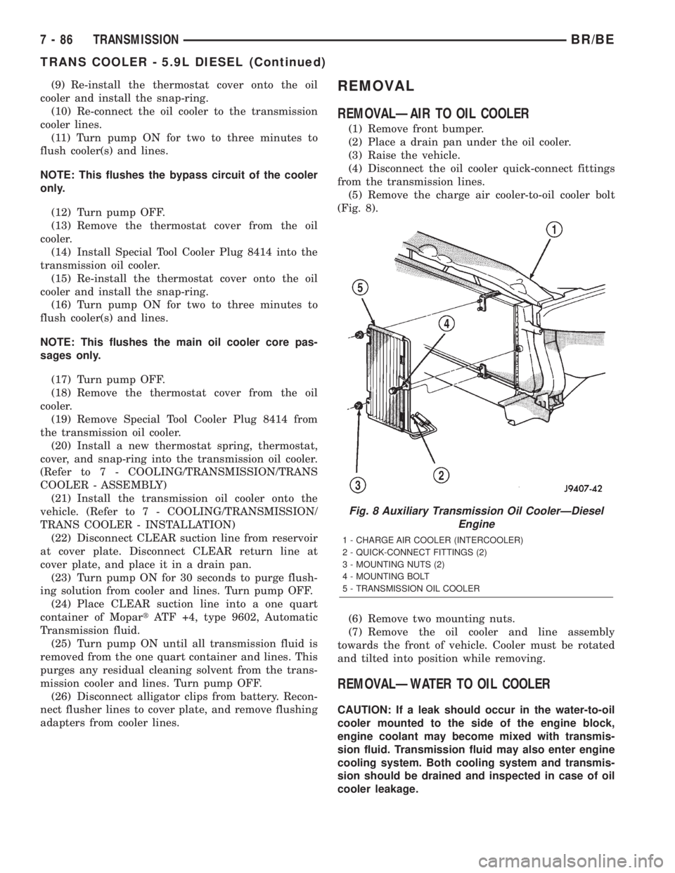
(5) Remove the charge air cooler-to-oil cooler bolt
(Fig. 8).
(6) Remove two mounting nuts.
(7) Remove the oil cooler and line assembly
towards the front of vehicle. Cooler must be rotated
and tilted into position while removing.
REMOVALÐWATER TO OIL COOLER
CAUTION: If a leak should occur in the water-to-oil
cooler mounted to the side of the engine block,
engine coolant may become mixed with transmis-
sion fluid. Transmission fluid may also enter engine
cooling system. Both cooling system and transmis-
sion should be drained and inspected in case of oil
cooler leakage.
Fig. 8 Auxiliary Transmission Oil CoolerÐDiesel
Engine
1 - CHARGE AIR COOLER (INTERCOOLER)
2 - QUICK-CONNECT FITTINGS (2)
3 - MOUNTING NUTS (2)
4 - MOUNTING BOLT
5 - TRANSMISSION OIL COOLER
7 - 86 TRANSMISSIONBR/BE
TRANS COOLER - 5.9L DIESEL (Continued)
Page 678 of 2255
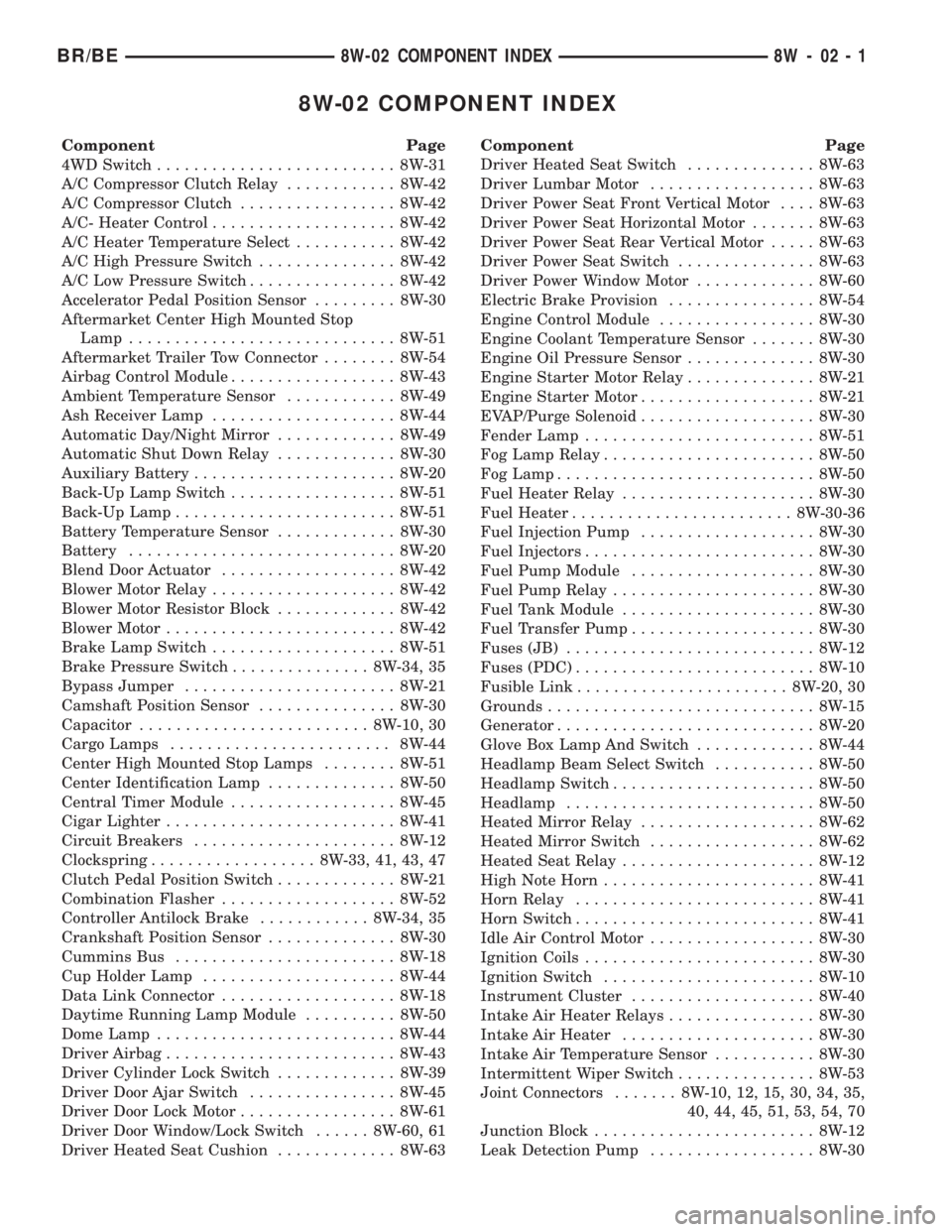
8W-02 COMPONENT INDEX
Component Page
4WD Switch.......................... 8W-31
A/C Compressor Clutch Relay............ 8W-42
A/C Compressor Clutch................. 8W-42
A/C- Heater Control.................... 8W-42
A/C Heater Temperature Select........... 8W-42
A/C High Pressure Switch............... 8W-42
A/C Low Pressure Switch................ 8W-42
Accelerator Pedal Position Sensor......... 8W-30
Aftermarket Center High Mounted Stop
Lamp............................. 8W-51
Aftermarket Trailer Tow Connector........ 8W-54
Airbag Control Module.................. 8W-43
Ambient Temperature Sensor............ 8W-49
Ash Receiver Lamp.................... 8W-44
Automatic Day/Night Mirror............. 8W-49
Automatic Shut Down Relay............. 8W-30
Auxiliary Battery...................... 8W-20
Back-Up Lamp Switch.................. 8W-51
Back-Up Lamp........................ 8W-51
Battery Temperature Sensor............. 8W-30
Battery............................. 8W-20
Blend Door Actuator................... 8W-42
Blower Motor Relay.................... 8W-42
Blower Motor Resistor Block............. 8W-42
Blower Motor......................... 8W-42
Brake Lamp Switch.................... 8W-51
Brake Pressure Switch............... 8W-34, 35
Bypass Jumper....................... 8W-21
Camshaft Position Sensor............... 8W-30
Capacitor......................... 8W-10, 30
Cargo Lamps........................ 8W-44
Center High Mounted Stop Lamps........ 8W-51
Center Identification Lamp.............. 8W-50
Central Timer Module.................. 8W-45
Cigar Lighter......................... 8W-41
Circuit Breakers...................... 8W-12
Clockspring.................. 8W-33, 41, 43, 47
Clutch Pedal Position Switch............. 8W-21
Combination Flasher................... 8W-52
Controller Antilock Brake............ 8W-34, 35
Crankshaft Position Sensor.............. 8W-30
Cummins Bus........................ 8W-18
Cup Holder Lamp..................... 8W-44
Data Link Connector................... 8W-18
Daytime Running Lamp Module.......... 8W-50
Dome Lamp.......................... 8W-44
Driver Airbag......................... 8W-43
Driver Cylinder Lock Switch............. 8W-39
Driver Door Ajar Switch................ 8W-45
Driver Door Lock Motor................. 8W-61
Driver Door Window/Lock Switch...... 8W-60, 61
Driver Heated Seat Cushion............. 8W-63Component Page
Driver Heated Seat Switch.............. 8W-63
Driver Lumbar Motor.................. 8W-63
Driver Power Seat Front Vertical Motor.... 8W-63
Driver Power Seat Horizontal Motor....... 8W-63
Driver Power Seat Rear Vertical Motor..... 8W-63
Driver Power Seat Switch............... 8W-63
Driver Power Window Motor............. 8W-60
Electric Brake Provision................ 8W-54
Engine Control Module................. 8W-30
Engine Coolant Temperature Sensor....... 8W-30
Engine Oil Pressure Sensor.............. 8W-30
Engine Starter Motor Relay.............. 8W-21
Engine Starter Motor................... 8W-21
EVAP/Purge Solenoid................... 8W-30
Fender Lamp......................... 8W-51
Fog Lamp Relay....................... 8W-50
Fog Lamp............................ 8W-50
Fuel Heater Relay..................... 8W-30
Fuel Heater........................ 8W-30-36
Fuel Injection Pump................... 8W-30
Fuel Injectors......................... 8W-30
Fuel Pump Module.................... 8W-30
Fuel Pump Relay...................... 8W-30
Fuel Tank Module..................... 8W-30
Fuel Transfer Pump.................... 8W-30
Fuses (JB)........................... 8W-12
Fuses (PDC).......................... 8W-10
Fusible Link....................... 8W-20, 30
Grounds............................. 8W-15
Generator............................ 8W-20
Glove Box Lamp And Switch............. 8W-44
Headlamp Beam Select Switch........... 8W-50
Headlamp Switch...................... 8W-50
Headlamp........................... 8W-50
Heated Mirror Relay................... 8W-62
Heated Mirror Switch.................. 8W-62
Heated Seat Relay..................... 8W-12
High Note Horn....................... 8W-41
Horn Relay.......................... 8W-41
Horn Switch.......................... 8W-41
Idle Air Control Motor.................. 8W-30
Ignition Coils......................... 8W-30
Ignition Switch....................... 8W-10
Instrument Cluster.................... 8W-40
Intake Air Heater Relays................ 8W-30
Intake Air Heater..................... 8W-30
Intake Air Temperature Sensor........... 8W-30
Intermittent Wiper Switch............... 8W-53
Joint Connectors....... 8W-10, 12, 15, 30, 34, 35,
40, 44, 45, 51, 53, 54, 70
Junction Block........................ 8W-12
Leak Detection Pump.................. 8W-30
BR/BE8W-02 COMPONENT INDEX 8W - 02 - 1
Page 680 of 2255
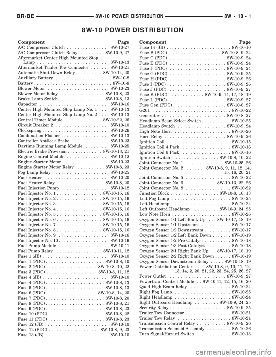
8W-10 POWER DISTRIBUTION
Component Page
A/C Compressor Clutch................ 8W-10-27
A/C Compressor Clutch Relay......... 8W-10-9, 27
Aftermarket Center High Mounted Stop
Lamp........................... 8W-10-13
Aftermarket Trailer Tow Connector....... 8W-10-21
Automatic Shut Down Relay.......... 8W-10-14, 20
Auxiliary Battery..................... 8W-10-8
Battery............................. 8W-10-8
Blower Motor....................... 8W-10-23
Blower Motor Relay................. 8W-10-8, 23
Brake Lamp Switch................. 8W-10-8, 13
Capacitor.......................... 8W-10-16
Center High Mounted Stop Lamp No. 1.... 8W-10-13
Center High Mounted Stop Lamp No. 2.... 8W-10-13
Central Timer Module.............. 8W-10-22, 26
Circuit Breaker 2.................... 8W-10-10
Clockspring......................... 8W-10-26
Combination Flasher.................. 8W-10-13
Controller Antilock Brake.............. 8W-10-23
Daytime Running Lamp Module......... 8W-10-25
Electric Brake Provision............. 8W-10-13, 21
Engine Control Module................ 8W-10-12
Engine Starter Motor................. 8W-10-23
Engine Starter Motor Relay........... 8W-10-8, 23
Fog Lamp Relay..................... 8W-10-25
Fuel Heater........................ 8W-10-20
Fuel Heater Relay.................. 8W-10-8, 20
Fuel Injection Pump.................. 8W-10-12
Fuel Injector No. 1................. 8W-10-15, 16
Fuel Injector No. 2................. 8W-10-15, 16
Fuel Injector No. 3................. 8W-10-15, 16
Fuel Injector No. 4................. 8W-10-15, 16
Fuel Injector No. 5................. 8W-10-15, 16
Fuel Injector No. 6................. 8W-10-15, 16
Fuel Injector No. 7................. 8W-10-15, 16
Fuel Injector No. 8................. 8W-10-15, 16
Fuel Injector No. 9................... 8W-10-16
Fuel Injector No. 10................... 8W-10-16
Fuel Pump Module................... 8W-10-11
Fuel Pump Relay.................. 8W-10-11, 12
Fuse 1 (JB)......................... 8W-10-10
Fuse 1 (PDC)...................... 8W-10-8, 10
Fuse 2 (PDC)................... 8W-10-8, 10, 22
Fuse 3 (PDC)................... 8W-10-8, 11, 12
Fuse 4 (JB)......................... 8W-10-10
Fuse 4 (PDC)...................... 8W-10-8, 13
Fuse 5 (PDC)...................... 8W-10-8, 13
Fuse 6 (PDC)................... 8W-10-8, 14, 20
Fuse 7 (PDC)...................... 8W-10-8, 20
Fuse 8 (PDC)...................... 8W-10-8, 21
Fuse 9 (PDC)...................... 8W-10-8, 23
Fuse 10 (PDC)..................... 8W-10-8, 22
Fuse 11 (PDC)..................... 8W-10-8, 23
Fuse 12 (JB)........................ 8W-10-10
Fuse 12 (PDC)................... 8W-10-8, 9, 23
Fuse 13 (JB)........................ 8W-10-10
Component Page
Fuse 14 (JB)........................ 8W-10-10
Fuse B (PDC)................... 8W-10-8, 9, 24
Fuse C (PDC)..................... 8W-10-9, 24
Fuse E (PDC)..................... 8W-10-9, 24
Fuse F (PDC)..................... 8W-10-9, 24
Fuse G (PDC)..................... 8W-10-9, 25
Fuse H (PDC)..................... 8W-10-9, 26
Fuse I (PDC)...................... 8W-10-9, 26
Fuse J (PDC)...................... 8W-10-9, 27
Fuse K (PDC)............. 8W-10-9, 14, 17, 18, 19
Fuse L (PDC)..................... 8W-10-9, 27
Fuse Gen (PDC)................... 8W-10-8, 27
G201............................. 8W-10-22
Generator........................ 8W-10-8, 27
Headlamp Beam Select Switch........... 8W-10-25
Headlamp Switch.................. 8W-10-9, 24
High Note Horn..................... 8W-10-26
Horn Relay....................... 8W-10-9, 26
Ignition Coil........................ 8W-10-15
Ignition Coil 4 Pack................... 8W-10-16
Ignition Coil 6 Pack................... 8W-10-16
Ignition Switch................. 8W-10-8, 10, 22
Joint Connector No. 1.............. 8W-10-25, 26
Joint Connector No. 2........ 8W-10-8, 9, 11, 12, 14,
15, 16, 20, 21
Joint Connector No. 5................. 8W-10-22
Joint Connector No. 6............ 8W-10-13, 22, 26
Joint Connector No. 8................. 8W-10-22
Junction Block.................. 8W-10-8, 10, 13
Left Fog Lamp...................... 8W-10-25
Left Headlamp...................... 8W-10-24
Left Outboard Headlamp.......... 8W-10-9, 24, 25
Low Note Horn...................... 8W-10-26
Oxygen Sensor 1/1 Left Bank Up . . . 8W-10-17, 18, 19
Oxygen Sensor 1/1 Upstream............ 8W-10-17
Oxygen Sensor 1/2 Downstream.......... 8W-10-17
Oxygen Sensor 1/2 Left Bank Down....... 8W-10-19
Oxygen Sensor 1/2 Pre-Catalyst.......... 8W-10-18
Oxygen Sensor 1/3 Post-Catalyst......... 8W-10-18
Oxygen Sensor 2/1 Right Bank Up . . 8W-10-17, 18, 19
Oxygen Sensor 2/2 Right Bank Down...... 8W-10-19
Oxygen Sensor Downstream Relay..... 8W-10-18, 19
Power Distribution Center.... 8W-10-8, 9, 10, 11, 12,
13, 14, 2, 20, 21, 22, 23, 24, 25, 26, 27
Power Outlet...................... 8W-10-9, 27
Powertrain Control Module . . 8W-10-11, 12, 15, 16, 20
Quad High Beam Relay................ 8W-10-24
Right Fog Lamp..................... 8W-10-25
Right Headlamp..................... 8W-10-24
Right Outboard Headlamp......... 8W-10-9, 24, 25
Security Relay..................... 8W-10-9, 25
Trailer Tow Connector................. 8W-10-21
Trailer Tow Relay.................... 8W-10-21
Transmission Control Relay........... 8W-10-9, 26
Transmission Solenoid Assembly......... 8W-10-26
Turn Signal/Hazard Switch............. 8W-10-13
BR/BE8W-10 POWER DISTRIBUTION 8W - 10 - 1
Page 730 of 2255
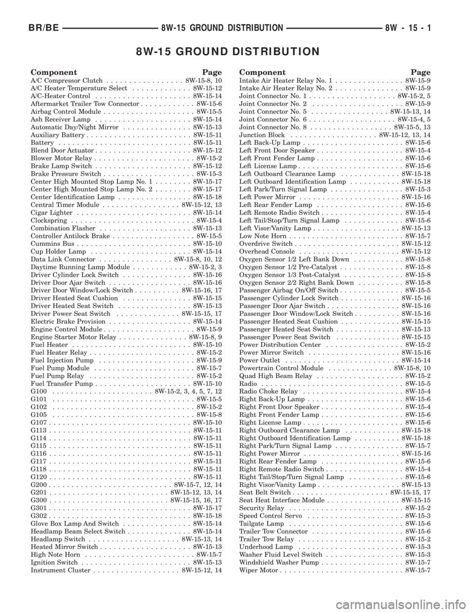
8W-15 GROUND DISTRIBUTION
Component Page
A/C Compressor Clutch.................8W-15-8, 10
A/C Heater Temperature Select.............8W-15-12
A/C-Heater Control.....................8W-15-14
Aftermarket Trailer Tow Connector............8W-15-6
Airbag Control Module....................8W-15-5
Ash Receiver Lamp.....................8W-15-14
Automatic Day/Night Mirror...............8W-15-13
Auxiliary Battery.......................8W-15-11
Battery.............................8W-15-11
Blend Door Actuator.....................8W-15-12
Blower Motor Relay......................8W-15-2
Brake Lamp Switch.....................8W-15-12
Brake Pressure Switch....................8W-15-3
Center High Mounted Stop Lamp No. 1........8W-15-17
Center High Mounted Stop Lamp No. 2........8W-15-17
Center Identification Lamp................8W-15-18
Central Timer Module.................8W-15-12, 13
Cigar Lighter.........................8W-15-14
Clockspring...........................8W-15-4
Combination Flasher....................8W-15-13
Controller Antilock Brake..................8W-15-5
Cummins Bus.........................8W-15-10
Cup Holder Lamp......................8W-15-14
Data Link Connector................8W-15-8, 10, 12
Daytime Running Lamp Module............8W-15-2, 3
Driver Cylinder Lock Switch...............8W-15-16
Driver Door Ajar Switch..................8W-15-16
Driver Door Window/Lock Switch..........8W-15-16, 17
Driver Heated Seat Cushion...............8W-15-15
Driver Heated Seat Switch................8W-15-13
Driver Power Seat Switch..............8W-15-15, 17
Electric Brake Provision..................8W-15-14
Engine Control Module....................8W-15-9
Engine Starter Motor Relay...............8W-15-8, 9
Fuel Heater..........................8W-15-10
Fuel Heater Relay.......................8W-15-2
Fuel Injection Pump.....................8W-15-9
Fuel Pump Module......................8W-15-7
Fuel Pump Relay.......................8W-15-2
Fuel Transfer Pump.....................8W-15-10
G100......................8W-15-2, 3, 4, 5, 7, 12
G101...............................8W-15-5
G102...............................8W-15-2
G105...............................8W-15-8
G107...............................8W-15-10
G113...............................8W-15-11
G114...............................8W-15-11
G115...............................8W-15-11
G116...............................8W-15-11
G117...............................8W-15-11
G118...............................8W-15-11
G120...............................8W-15-11
G200...........................8W-15-7, 12, 14
G201..........................8W-15-12, 13, 14
G300..........................8W-15-15, 16, 17
G301...............................8W-15-17
G302...............................8W-15-18
Glove Box Lamp And Switch...............8W-15-14
Headlamp Beam Select Switch..............8W-15-14
Headlamp Switch....................8W-15-13, 14
Heated Mirror Switch....................8W-15-13
High Note Horn........................8W-15-7
Ignition Switch........................8W-15-13
Instrument Cluster...................8W-15-12, 14
Component Page
Intake Air Heater Relay No. 1...............8W-15-9
Intake Air Heater Relay No. 2...............8W-15-9
Joint Connector No. 1...................8W-15-2, 5
Joint Connector No. 2....................8W-15-9
Joint Connector No. 5.................8W-15-13, 14
Joint Connector No. 6...................8W-15-4, 5
Joint Connector No. 8..................8W-15-5, 13
Junction Block...................8W-15-12, 13, 14
Left Back-Up Lamp......................8W-15-6
Left Front Door Speaker...................8W-15-4
Left Front Fender Lamp...................8W-15-6
Left License Lamp.......................8W-15-6
Left Outboard Clearance Lamp.............8W-15-18
Left Outboard Identification Lamp...........8W-15-18
Left Park/Turn Signal Lamp................8W-15-3
Left Power Mirror......................8W-15-16
Left Rear Fender Lamp...................8W-15-6
Left Remote Radio Switch..................8W-15-4
Left Tail/Stop/Turn Signal Lamp.............8W-15-6
Left Visor/Vanity Lamp...................8W-15-13
Low Note Horn.........................8W-15-7
Overdrive Switch.......................8W-15-12
Overhead Console......................8W-15-12
Oxygen Sensor 1/2 Left Bank Down...........8W-15-8
Oxygen Sensor 1/2 Pre-Catalyst..............8W-15-8
Oxygen Sensor 1/3 Post-Catalyst.............8W-15-8
Oxygen Sensor 2/2 Right Bank Down..........8W-15-8
Passenger Airbag On/Off Switch..............8W-15-5
Passenger Cylinder Lock Switch.............8W-15-16
Passenger Door Ajar Switch................8W-15-16
Passenger Door Window/Lock Switch..........8W-15-16
Passenger Heated Seat Cushion.............8W-15-15
Passenger Heated Seat Switch..............8W-15-13
Passenger Power Seat Switch..............8W-15-15
Power Distribution Center.................8W-15-2
Power Mirror Switch....................8W-15-16
Power Outlet.........................8W-15-14
Powertrain Control Module..............8W-15-8, 10
Quad High Beam Relay...................8W-15-2
Radio...............................8W-15-5
Radio Choke Relay......................8W-15-4
Right Back-Up Lamp.....................8W-15-6
Right Front Door Speaker..................8W-15-4
Right Front Fender Lamp..................8W-15-6
Right License Lamp......................8W-15-6
Right Outboard Clearance Lamp............8W-15-18
Right Outboard Identification Lamp..........8W-15-18
Right Park/Turn Signal Lamp...............8W-15-7
Right Power Mirror.....................8W-15-16
Right Rear Fender Lamp..................8W-15-6
Right Remote Radio Switch.................8W-15-4
Right Tail/Stop/Turn Signal Lamp............8W-15-6
Right Visor/Vanity Lamp..................8W-15-13
Seat Belt Switch.....................8W-15-15, 17
Seat Heat Interface Module................8W-15-15
Security Relay.........................8W-15-2
Speed Control Servo.....................8W-15-3
Tailgate Lamp.........................8W-15-6
Trailer Tow Connector....................8W-15-6
Trailer Tow Relay.......................8W-15-2
Underhood Lamp.......................8W-15-3
Washer Fluid Level Switch.................8W-15-3
Windshield Washer Pump..................8W-15-7
Wiper Motor...........................8W-15-7
BR/BE8W-15 GROUND DISTRIBUTION 8W - 15 - 1
Page 752 of 2255
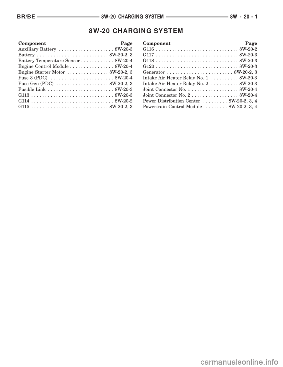
8W-20 CHARGING SYSTEM
Component Page
Auxiliary Battery.................... 8W-20-3
Battery.......................... 8W-20-2, 3
Battery Temperature Sensor............ 8W-20-4
Engine Control Module................ 8W-20-4
Engine Starter Motor............... 8W-20-2, 3
Fuse 3 (PDC)....................... 8W-20-4
Fuse Gen (PDC)................... 8W-20-2, 3
Fusible Link........................ 8W-20-3
G113 .............................. 8W-20-3
G114 .............................. 8W-20-2
G115 ............................ 8W-20-2, 3Component Page
G116 .............................. 8W-20-2
G117 .............................. 8W-20-3
G118 .............................. 8W-20-3
G120.............................. 8W-20-3
Generator........................ 8W-20-2, 3
Intake Air Heater Relay No. 1.......... 8W-20-3
Intake Air Heater Relay No. 2.......... 8W-20-3
Joint Connector No. 1................. 8W-20-4
Joint Connector No. 2................. 8W-20-4
Power Distribution Center......... 8W-20-2, 3, 4
Powertrain Control Module......... 8W-20-2, 3, 4
BR/BE8W-20 CHARGING SYSTEM 8W - 20 - 1
Page 756 of 2255
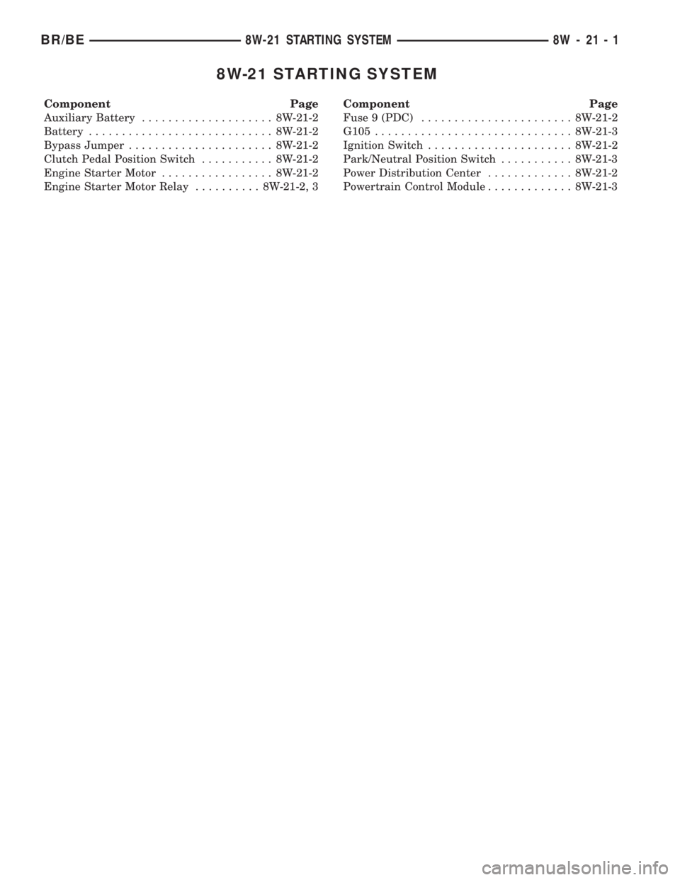
8W-21 STARTING SYSTEM
Component Page
Auxiliary Battery.................... 8W-21-2
Battery............................ 8W-21-2
Bypass Jumper...................... 8W-21-2
Clutch Pedal Position Switch........... 8W-21-2
Engine Starter Motor................. 8W-21-2
Engine Starter Motor Relay.......... 8W-21-2, 3Component Page
Fuse 9 (PDC)....................... 8W-21-2
G105.............................. 8W-21-3
Ignition Switch...................... 8W-21-2
Park/Neutral Position Switch........... 8W-21-3
Power Distribution Center............. 8W-21-2
Powertrain Control Module............. 8W-21-3
BR/BE8W-21 STARTING SYSTEM 8W - 21 - 1
Page 1201 of 2255
(8) Connect the engine harness connector and
ground cable to the PDC.
(9) Connect the vacuum pump supply hose.
(10) Connect the APPS connector (Fig. 5).
(11) Install the APPS assembly bracket to the cyl-
inder head bracket.
(12) Install the throttle linkage cover.
(13) Connect the power steering pressure and
return lines.
(14) Connect the passenger battery ground cable to
the engine block. Tighten the bolt to 77 N´m (57 ft.
lbs.) torque.
(15) Connect the engine block heater connector.
(16) Connect the a/c compressor electrical connec-
tors.
(17) Install the charge air cooler and a/c condenser
(if a/c equipped). Install and tighten the charge air
cooler mounting bolts to 2 N´m (17 in. lbs.) torque.
(18) Connect the charge air cooler piping. Torque
all clamps to 8 N´m (72 in. lbs.) torque.
(19) Connect the a/c refrigerant lines to the a/c
condenser (if equipped).
(20) Install the front bumper (Refer to 13 -
FRAMES & BUMPERS/BUMPERS/FRONT
BUMPER - INSTALLATION).(21) Install the radiator upper support panel.
(22) Install the radiator (Refer to 7 - COOLING/
ENGINE/RADIATOR - INSTALLATION).
(23) Connect the transmission quick-connect oil
cooler lines to the radiator. Push together until an
audible ªclickº is heard. Verify connection by pulling
apart.
(24) Raise vehicle.
(25) Connect a/c compressor suction/discharge hose
(if a/c equipped).
(26) Install the radiator lower hose and clamps.
(27) Install the starter motor (Refer to 8 - ELEC-
TRICAL/STARTING/STARTER MOTOR - INSTAL-
LATION).
(28) Install the transmission and transfer case (if
equipped).
(29) Connect the exhaust pipe to the turbocharger
elbow (Fig. 3). Torque the bolts to 34 N´m (25 ft. lbs.)
torque.
(30) Connect the transmission auxiliary oil cooler
lines (if equipped).
(31) Lower the vehicle
(32) Connect the heater core supply and return
hoses.
(33) Install the cooling fan and shroud at the same
time (Refer to 7 - COOLING/ENGINE/RADIATOR
FAN - INSTALLATION).
(34) Install the coolant recovery bottle to the fan
shroud (Fig. 2) and connect the hose to the radiator
filler neck.
(35) Install the windshield washer bottle to the fan
shroud and connect the pump supply hose and elec-
trical connections.
(36) Install the radiator upper hose and clamps.
(37) Change oil filter and install new engine oil.
(38) Fill cooling system with coolant (Refer to 7 -
COOLING - STANDARD PROCEDURE).
(39) Connect battery negative cables.
(40) Perform the fuel line air bleed procedure
(Refer to 14 - FUEL SYSTEM/FUEL DELIVERY -
STANDARD PROCEDURE).
(41) Start engine and inspect for engine oil, cool-
ant, and fuel leaks.
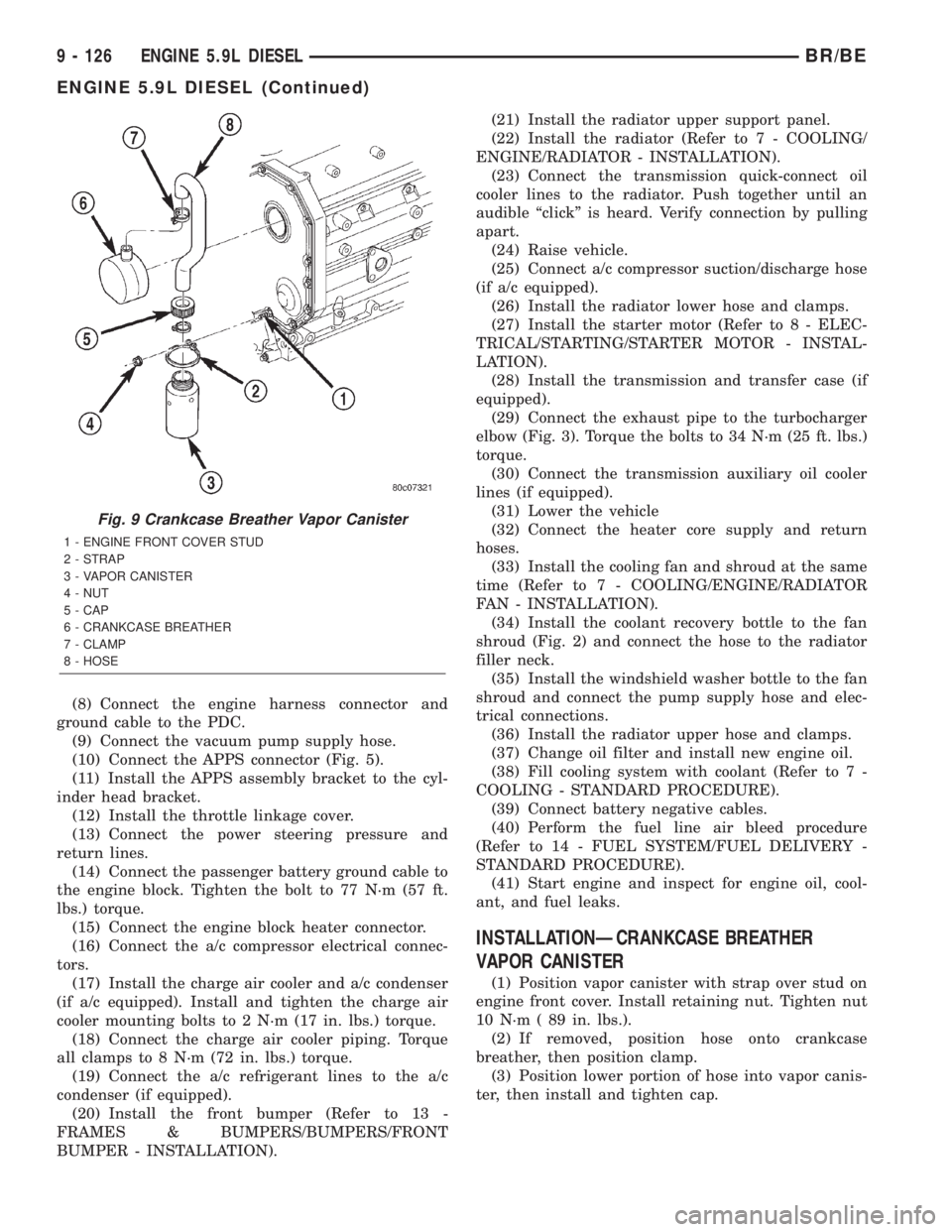
INSTALLATIONÐCRANKCASE BREATHER
VAPOR CANISTER
(1) Position vapor canister with strap over stud on
engine front cover. Install retaining nut. Tighten nut
10 N´m ( 89 in. lbs.).
(2) If removed, position hose onto crankcase
breather, then position clamp.
(3) Position lower portion of hose into vapor canis-
ter, then install and tighten cap.
Fig. 9 Crankcase Breather Vapor Canister
1 - ENGINE FRONT COVER STUD
2 - STRAP
3 - VAPOR CANISTER
4 - NUT
5 - CAP
6 - CRANKCASE BREATHER
7 - CLAMP
8 - HOSE
9 - 126 ENGINE 5.9L DIESELBR/BE
ENGINE 5.9L DIESEL (Continued)
Page 1233 of 2255
(11) Install the cylinder head cover and reusable
gasket (Fig. 85) (Refer to 9 - ENGINE/CYLINDER
HEAD/CYLINDER HEAD COVER(S) - INSTALLA-
TION).
(12) Install gear housing cover (Refer to 9 -
ENGINE/VALVE TIMING/GEAR HOUSING COVER
- INSTALLATION).
(13) Install the crankshaft damper (Fig. 83) (Refer
to 9 - ENGINE/ENGINE BLOCK/VIBRATION
DAMPER - INSTALLATION).
(14) Install the fan support/hub assembly (Fig. 82)
and tighten bolts to 24 N´m (18 ft. lbs.) torque.
(15) Install the crankcase breather housing (Refer
to 9 - ENGINE - INSTALLATION).
(16) Install the charge air cooler (with a/c con-
denser and auxiliary transmission oil cooler, if
equipped) and tighten the mounting bolts to 2 N´m
(17 in. lbs.) torque.
(17) Connect charge air cooler inlet and outlet
pipes. Tighten clamps to 10 N´m (100 in. lbs.) torque.
(18) Install the radiator upper support panel.
(19) Close radiator petcock and lower the radiator
into the engine compartment. Tighten the mounting
bolts to 11 N´m (95 in. lbs.) torque.
(20) Raise vehicle on hoist.
(21) Connect radiator lower hose and install
clamp.
(22) Connect transmission auxiliary oil cooler lines
(if equipped).
(23) Lower vehicle.
(24) Install the fan shroud and tighten the mount-
ing screws to 6 N´m (50 in. lbs.) torque.
(25) Install the viscous fan/drive assembly (Refer
to 7 - COOLING/ENGINE/RADIATOR FAN -
INSTALLATION).
(26) Install the coolant recovery and windshield
washer fluid reservoirs to the fan shroud.
(27) Connect the coolant recovery hose to the radi-
ator filler neck.
(28) Install the accessory drive belt (Refer to 7 -
COOLING/ACCESSORY DRIVE/DRIVE BELTS -
INSTALLATION).
(29) Install the front bumper assembly (Refer to 13
- FRAMES & BUMPERS/BUMPERS/FRONT
BUMPER - INSTALLATION).
(30) Add engine coolant (Refer to 7 - COOLING -
STANDARD PROCEDURE).
(31) Charge A/C system with refrigerant (if A/C
equipped) (Refer to 24 - HEATING & AIR CONDI-
TIONING/PLUMBING - STANDARD PROCEDURE).
(32) Connect the battery negative cables.
(33) Start engine and check for engine oil and cool-
ant leaks.CONNECTING ROD BEARINGS
STANDARD PROCEDUREÐCONNECTING ROD
BEARING AND CRANKSHAFT JOURNAL
CLEARANCE
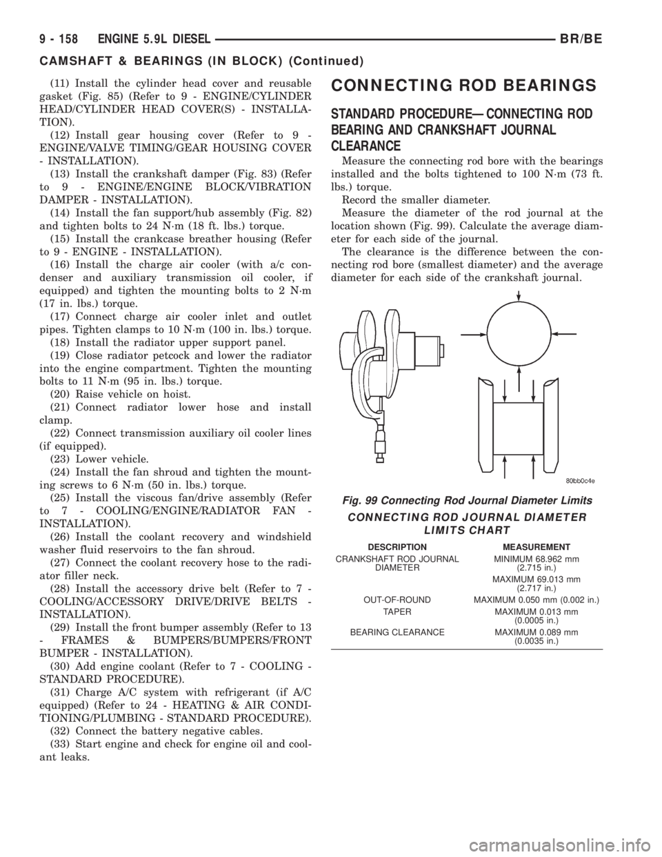
Measure the connecting rod bore with the bearings
installed and the bolts tightened to 100 N´m (73 ft.
lbs.) torque.
Record the smaller diameter.
Measure the diameter of the rod journal at the
location shown (Fig. 99). Calculate the average diam-
eter for each side of the journal.
The clearance is the difference between the con-
necting rod bore (smallest diameter) and the average
diameter for each side of the crankshaft journal.
Fig. 99 Connecting Rod Journal Diameter Limits
CONNECTING ROD JOURNAL DIAMETER
LIMITS CHART
DESCRIPTION MEASUREMENT
CRANKSHAFT ROD JOURNAL
DIAMETERMINIMUM 68.962 mm
(2.715 in.)
MAXIMUM 69.013 mm
(2.717 in.)
OUT-OF-ROUND MAXIMUM 0.050 mm (0.002 in.)
TAPER MAXIMUM 0.013 mm
(0.0005 in.)
BEARING CLEARANCE MAXIMUM 0.089 mm
(0.0035 in.)
9 - 158 ENGINE 5.9L DIESELBR/BE
CAMSHAFT & BEARINGS (IN BLOCK) (Continued)
Page 1287 of 2255
INSTALLATION
(1) Position the charge air cooler. Install the bolts
and tighten to 2 N´m (17 in. lbs.) torque.
(2) Install the air intake system tubes to the
charge air cooler. With the clamps in position, tighten
the clamps to 11 N´m (95 in. lbs.) torque.
(3) Install the transmission auxiliary cooler (if
equipped) (Refer to 7 - COOLING/TRANSMISSION/
TRANS COOLER - INSTALLATION).
(4) Install the A/C condenser (if A/C equipped)
(Refer to 24 - HEATING & AIR CONDITIONING/
PLUMBING/A/C CONDENSER - INSTALLATION).Recharge A/C system (Refer to 24 - HEATING & AIR
CONDITIONING/PLUMBING - STANDARD PRO-
CEDURE).
(5) Install the front support bracket. Install and
tighten the bolts.
(6) Install the front bumper (Refer to 13 -
FRAMES & BUMPERS/BUMPERS/FRONT
BUMPER - INSTALLATION).
(7) Connect the battery negative cables.
(8) Start engine and check for boost system leaks.
11 - 20 EXHAUST SYSTEMBR/BE
CHARGE AIR COOLER AND PLUMBING (Continued)