oil type DODGE RAM 2002 Service Repair Manual
[x] Cancel search | Manufacturer: DODGE, Model Year: 2002, Model line: RAM, Model: DODGE RAM 2002Pages: 2255, PDF Size: 62.07 MB
Page 2177 of 2255
(3) Tighten the accumulator retaining band screw
to 4.5 N´m (40 in. lbs.).
(4) Remove the tape or plugs from the refrigerant
line fittings on the suction line and the accumulator
outlet. Connect the suction line refrigerant line cou-
pler to the accumulator outlet. (Refer to 24 - HEAT-
ING & AIR CONDITIONING/PLUMBING -
STANDARD PROCEDURE - A/C LINE COUPLERS)
(5) Reinstall the a/c low pressure switch on the
accumulator. (Refer to 24 - HEATING & AIR CON-
DITIONING/CONTROLS/A/C LOW PRESSURE
SWITCH - INSTALLATION)
(6) Connect the battery negative cable.
(7) Evacuate the refrigerant system. (Refer to 24 -
HEATING & AIR CONDITIONING/PLUMBING -
STANDARD PROCEDURE - REFRIGERANT SYS-
TEM EVACUATE)
(8) Charge the refrigerant system. (Refer to 24 -
HEATING & AIR CONDITIONING/PLUMBING -
STANDARD PROCEDURE - REFRIGERANT SYS-
TEM CHARGE)
NOTE: If the accumulator is replaced, add 60 milli-
liters (2 fluid ounces) of refrigerant oil to the refrig-
erant system. Use only refrigerant oil of the type
recommended for the compressor in the vehicle.
HEATER CORE
DESCRIPTION
The heater core is located in the HVAC housing,
under the instrument panel. It is a heat exchanger
made of rows of tubes and fins.
The heater core is not repairable and if damaged it
must be replaced.
OPERATION
Engine coolant is circulated through heater hoses
to the heater core at all times. As the coolant flows
through the heater core, heat removed from the
engine is transferred to the heater core fins and
tubes. Air directed through the heater core picks up
the heat from the heater core fins. The blend door
allows control of the heater output air temperature
by controlling how much of the air flowing through
the HVAC housing is directed through the heater
core. The blower motor speed controls the volume of
air flowing through the HVAC housing.
The heater core cannot be repaired and, if faulty or
damaged, it must be replaced.
REMOVAL
(1) Remove the HVAC housing from the vehicle.
(Refer to 24 - HEATING & AIR CONDITIONING/
DISTRIBUTION/HVAC HOUSING - REMOVAL)(2) Remove the screws and retainers that secure
the heater core to the HVAC housing.
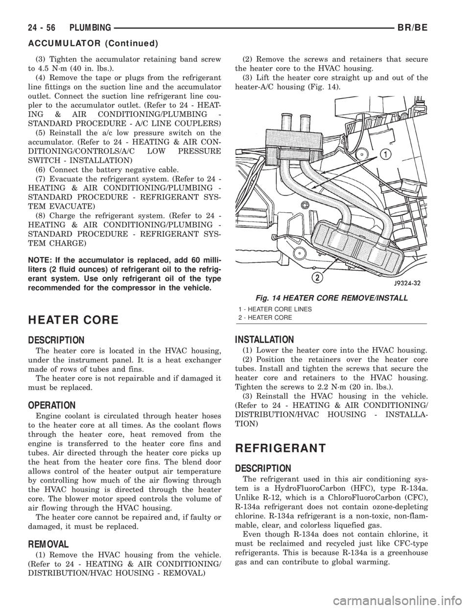
(3) Lift the heater core straight up and out of the
heater-A/C housing (Fig. 14).
INSTALLATION
(1) Lower the heater core into the HVAC housing.
(2) Position the retainers over the heater core
tubes. Install and tighten the screws that secure the
heater core and retainers to the HVAC housing.
Tighten the screws to 2.2 N´m (20 in. lbs.).
(3) Reinstall the HVAC housing in the vehicle.
(Refer to 24 - HEATING & AIR CONDITIONING/
DISTRIBUTION/HVAC HOUSING - INSTALLA-
TION)
REFRIGERANT
DESCRIPTION
The refrigerant used in this air conditioning sys-
tem is a HydroFluoroCarbon (HFC), type R-134a.
Unlike R-12, which is a ChloroFluoroCarbon (CFC),
R-134a refrigerant does not contain ozone-depleting
chlorine. R-134a refrigerant is a non-toxic, non-flam-
mable, clear, and colorless liquefied gas.
Even though R-134a does not contain chlorine, it
must be reclaimed and recycled just like CFC-type
refrigerants. This is because R-134a is a greenhouse
gas and can contribute to global warming.
Fig. 14 HEATER CORE REMOVE/INSTALL
1 - HEATER CORE LINES
2 - HEATER CORE
24 - 56 PLUMBINGBR/BE
ACCUMULATOR (Continued)
Page 2178 of 2255
OPERATION
R-134a refrigerant is not compatible with R-12
refrigerant in an air conditioning system. Even a
small amount of R-12 added to an R-134a refrigerant
system will cause compressor failure, refrigerant oil
sludge or poor air conditioning system performance.
In addition, the PolyAlkylene Glycol (PAG) synthetic
refrigerant oils used in an R-134a refrigerant system
are not compatible with the mineral-based refriger-
ant oils used in an R-12 refrigerant system.
R-134a refrigerant system service ports, service
tool couplers and refrigerant dispensing bottles have
all been designed with unique fittings to ensure that
an R-134a system is not accidentally contaminated
with the wrong refrigerant (R-12). There are also
labels posted in the engine compartment of the vehi-
cle and on the compressor identifying to service tech-
nicians that the air conditioning system is equipped
with R-134a.
REFRIGERANT OIL
DESCRIPTION
The refrigerant oil used in R-134a refrigerant sys-
tems is a synthetic-based, PolyAlkylene Glycol (PAG),
wax-free lubricant. Mineral-based R-12 refrigerant
oils are not compatible with PAG oils, and should
never be introduced to an R-134a refrigerant system.
There are different PAG oils available, and each
contains a different additive package. The SD7H15
compressor used in this vehicle is designed to use an
SP-20 PAG refrigerant oil. Use only refrigerant oil of
this same type to service the refrigerant system.
OPERATION
After performing any refrigerant recovery or recy-
cling operation, always replenish the refrigerant sys-
tem with the same amount of the recommended
refrigerant oil as was removed. Too little refrigerant
oil can cause compressor damage, and too much can
reduce air conditioning system performance.
PAG refrigerant oil is much more hygroscopic than
mineral oil, and will absorb any moisture it comes
into contact with, even moisture in the air. The PAG
oil container should always be kept tightly capped
until it is ready to be used. After use, recap the oil
container immediately to prevent moisture contami-
nation.
STANDARD PROCEDURE - REFRIGERANT OIL
LEVEL
When an air conditioning system is assembled at
the factory, all components except the compressor are
refrigerant oil free. After the refrigerant system has
been charged and operated, the refrigerant oil in the
compressor is dispersed throughout the refrigerant
system. The accumulator, evaporator, condenser, and
compressor will each retain a significant amount of
the needed refrigerant oil.
It is important to have the correct amount of oil in
the refrigerant system. This ensures proper lubrica-
tion of the compressor. Too little oil will result in
damage to the compressor. Too much oil will reduce
the cooling capacity of the air conditioning system.
It will not be necessary to check the oil level in the
compressor or to add oil, unless there has been an oil
loss. An oil loss may occur due to a rupture or leak
from a refrigerant line, a connector fitting, a compo-
nent, or a component seal. If a leak occurs, add 30
milliliters (1 fluid ounce) of refrigerant oil to the
refrigerant system after the repair has been made.
Refrigerant oil loss will be evident at the leak point
by the presence of a wet, shiny surface around the
leak.
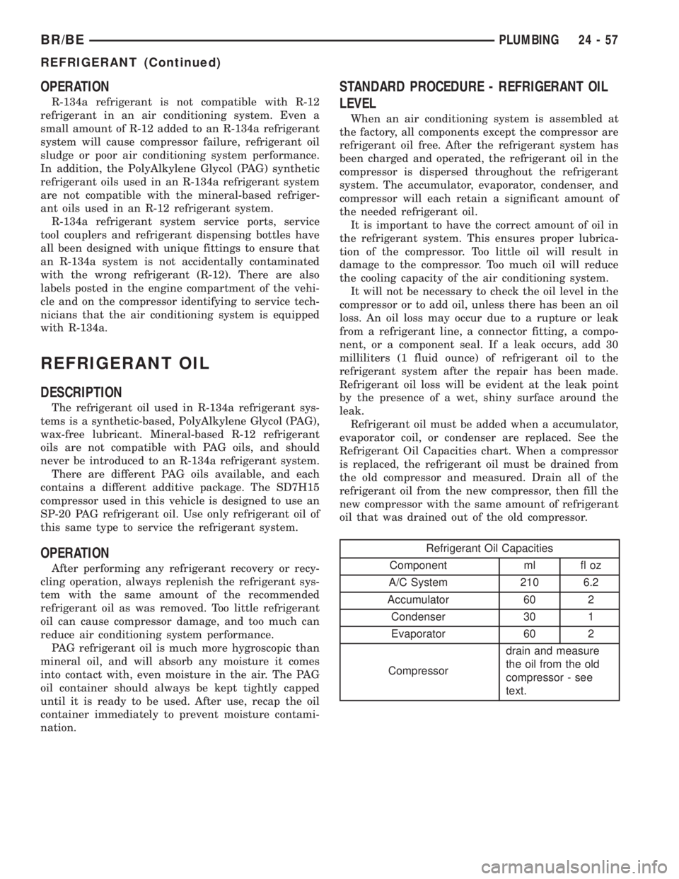
Refrigerant oil must be added when a accumulator,
evaporator coil, or condenser are replaced. See the
Refrigerant Oil Capacities chart. When a compressor
is replaced, the refrigerant oil must be drained from
the old compressor and measured. Drain all of the
refrigerant oil from the new compressor, then fill the
new compressor with the same amount of refrigerant
oil that was drained out of the old compressor.
Refrigerant Oil Capacities
Component ml fl oz
A/C System 210 6.2
Accumulator 60 2
Condenser 30 1
Evaporator 60 2
Compressordrain and measure
the oil from the old
compressor - see
text.
BR/BEPLUMBING 24 - 57
REFRIGERANT (Continued)