reset DODGE RAM 2002 Service Repair Manual
[x] Cancel search | Manufacturer: DODGE, Model Year: 2002, Model line: RAM, Model: DODGE RAM 2002Pages: 2255, PDF Size: 62.07 MB
Page 30 of 2255
CORRECTED CASTER CHART-CAB CHASSIS
Caster
Correlation
Value
(inches)4x2 8800
lb. GVW
134.7 in.
wheel
base4x4 8800
lb. GVW
4x2 & 4x4
11000 lb.
GVW
134.7 &
138.7 in.
wheel
base4x2 & 4x4
11000 lb.
GVW 162.7
in. wheel
base
Caster 1
deg.Caster 1
deg.Caster 1
deg.
25.00 4.27É 3.77É 3.81É
24.75 4.39É 3.89É 3.91É
24.50 4.51É 4.01É 4.01É
24.25 4.64É 4.14É 4.11É
24.00 4.76É 4.26É 4.21É
23.75 4.88É 4.38É 4.31É
23.50 5.00É 4.50É 4.41É
23.25 5.12É 4.62É 4.51É
23.00 5.25É 4.75É 4.61É
22.75 5.37É 4.87É 4.71É
22.50 5.49É 4.99É 4.81É
22.25 5.61É 5.11É 4.91É
22.00 5.74É 5.24É 5.01É
21.75 5.86É 5.36É 5.11É
21.50 5.98É 5.48É 5.21É
21.25 6.10É 5.60É 5.31É
21.00 6.23É 5.73É 5.41É
20.75 6.33É 5.83É 5.51É
20.50 6.47É 5.97É 5.61É
20.25 6.59É 6.09É 5.71É
0.00 6.71É 6.21É 5.81É
STANDARD PROCEDURE - ALIGNMENT
LINK/COIL SUSPENSION
Before each alignment reading the vehicle should
be jounced (rear first, then front). Grasp each
bumper at the center and jounce the vehicle up and
down several times. Always release the bumper in
the down position.Set the front end alignment to
specifications while the vehicle is in its NOR-
MALLY LOADED CONDITION.
CAMBER:The wheel camber angle is preset and
is not adjustable.
CASTER:Check the caster of the front axle for
correct angle. Be sure the axle is not bent or twisted.Road test the vehicle and make left and right turn.
Observe the steering wheel return-to-center position.
Low caster will cause poor steering wheel returnabil-
ity.
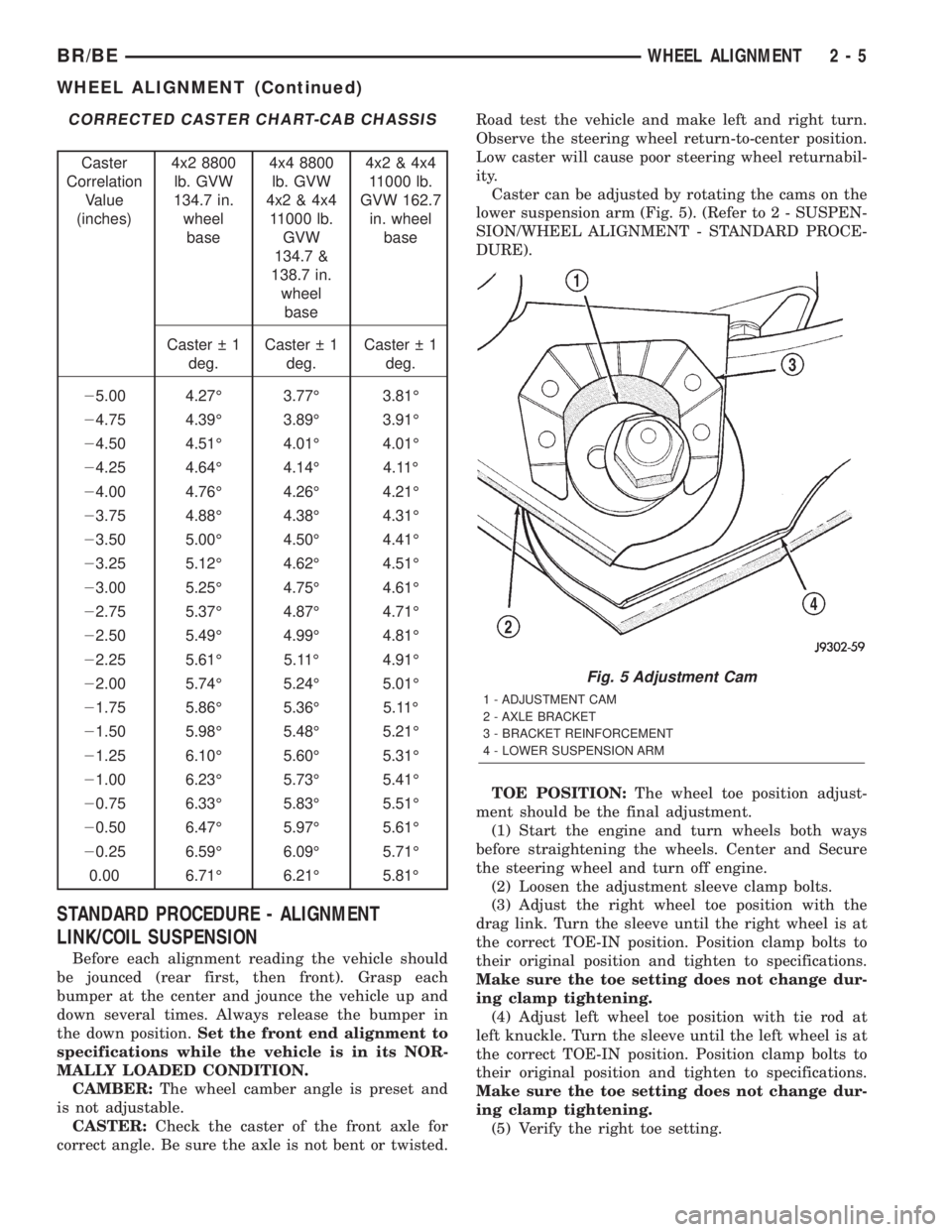
Caster can be adjusted by rotating the cams on the
lower suspension arm (Fig. 5). (Refer to 2 - SUSPEN-
SION/WHEEL ALIGNMENT - STANDARD PROCE-
DURE).
TOE POSITION:The wheel toe position adjust-
ment should be the final adjustment.
(1) Start the engine and turn wheels both ways
before straightening the wheels. Center and Secure
the steering wheel and turn off engine.
(2) Loosen the adjustment sleeve clamp bolts.
(3) Adjust the right wheel toe position with the
drag link. Turn the sleeve until the right wheel is at
the correct TOE-IN position. Position clamp bolts to
their original position and tighten to specifications.
Make sure the toe setting does not change dur-
ing clamp tightening.
(4) Adjust left wheel toe position with tie rod at
left knuckle. Turn the sleeve until the left wheel is at
the correct TOE-IN position. Position clamp bolts to
their original position and tighten to specifications.
Make sure the toe setting does not change dur-
ing clamp tightening.
(5) Verify the right toe setting.
Fig. 5 Adjustment Cam
1 - ADJUSTMENT CAM
2 - AXLE BRACKET
3 - BRACKET REINFORCEMENT
4 - LOWER SUSPENSION ARM
BR/BEWHEEL ALIGNMENT 2 - 5
WHEEL ALIGNMENT (Continued)
Page 223 of 2255
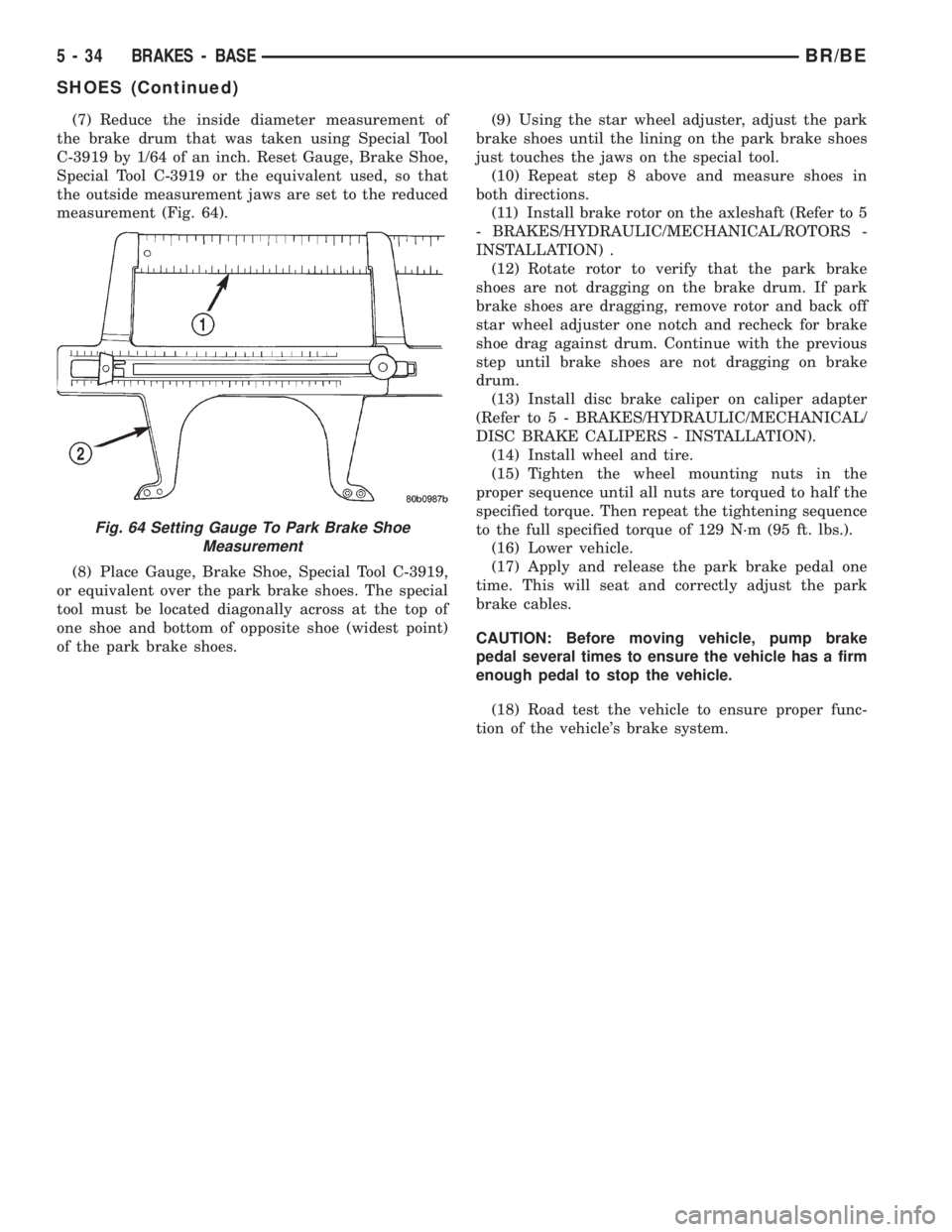
(7) Reduce the inside diameter measurement of
the brake drum that was taken using Special Tool
C-3919 by 1/64 of an inch. Reset Gauge, Brake Shoe,
Special Tool C-3919 or the equivalent used, so that
the outside measurement jaws are set to the reduced
measurement (Fig. 64).
(8) Place Gauge, Brake Shoe, Special Tool C-3919,
or equivalent over the park brake shoes. The special
tool must be located diagonally across at the top of
one shoe and bottom of opposite shoe (widest point)
of the park brake shoes.(9) Using the star wheel adjuster, adjust the park
brake shoes until the lining on the park brake shoes
just touches the jaws on the special tool.
(10) Repeat step 8 above and measure shoes in
both directions.
(11) Install brake rotor on the axleshaft (Refer to 5
- BRAKES/HYDRAULIC/MECHANICAL/ROTORS -
INSTALLATION) .
(12) Rotate rotor to verify that the park brake
shoes are not dragging on the brake drum. If park
brake shoes are dragging, remove rotor and back off
star wheel adjuster one notch and recheck for brake
shoe drag against drum. Continue with the previous
step until brake shoes are not dragging on brake
drum.
(13) Install disc brake caliper on caliper adapter
(Refer to 5 - BRAKES/HYDRAULIC/MECHANICAL/
DISC BRAKE CALIPERS - INSTALLATION).
(14) Install wheel and tire.
(15) Tighten the wheel mounting nuts in the
proper sequence until all nuts are torqued to half the
specified torque. Then repeat the tightening sequence
to the full specified torque of 129 N´m (95 ft. lbs.).
(16) Lower vehicle.
(17) Apply and release the park brake pedal one
time. This will seat and correctly adjust the park
brake cables.
CAUTION: Before moving vehicle, pump brake
pedal several times to ensure the vehicle has a firm
enough pedal to stop the vehicle.
(18) Road test the vehicle to ensure proper func-
tion of the vehicle's brake system.
Fig. 64 Setting Gauge To Park Brake Shoe
Measurement
5 - 34 BRAKES - BASEBR/BE
SHOES (Continued)
Page 347 of 2255
RADIO
DESCRIPTION
Available factory-installed radio receivers for this
model include an AM/FM/cassette (RAS sales code),
an AM/FM/CD/3-band graphic equalizer (RBR sales
code), or an AM/FM/CD/cassette/3-band graphic
equalizer (RAZ sales code). The factory-installed RAZ
sales code radio receivers can also communicate on
the Chrysler Collision Detection (CCD) data bus net-
work through a separate two-way wire harness con-
nector. All factory-installed receivers are stereo
Electronically Tuned Radios (ETR) and include an
electronic digital clock function.
These radio receivers can only be serviced by an
authorized radio repair station. See the latest War-
ranty Policies and Procedures manual for a current
listing of authorized radio repair stations.
All vehicles are equipped with an Ignition-Off
Draw (IOD) fuse that is removed when the vehicle is
shipped from the factory. This fuse feeds various
accessories that require battery current when the
ignition switch is in the Off position, including the
clock. The IOD fuse is removed to prevent battery
discharge during vehicle storage.
When removing or installing the IOD fuse, it is
important that the ignition switch be in the Off posi-
tion. Failure to place the ignition switch in the Off
position can cause the radio display to become scram-
bled when the IOD fuse is removed and replaced.
Removing and replacing the IOD fuse again, with the
ignition switch in the Off position, will correct the
scrambled display condition.
The IOD fuse should be checked if the radio or
clock displays are inoperative. The IOD fuse is
located in the junction block. Refer to the fuse layout
label on the back of the instrument panel fuse access
panel for IOD fuse identification and location.
OPERATION
The radio receiver operates on fused battery cur-
rent that is available only when the ignition switch is
in the On or Accessory positions. The electronic digi-
tal clock function of the radio operates on fused bat-
tery current supplied through the IOD fuse,
regardless of the ignition switch position.
For more information on the features, setting pro-
cedures, and control functions for each of the avail-
able factory-installed radio receivers, see the owner's
manual in the vehicle glove box. For complete circuit
diagrams, refer to the appropriate wiring informa-
tion. The wiring information includes wiring dia-
grams, proper wire and connector repair procedures,
details of wire harness routing and retention, connec-
tor pin-out information and location views for the
various wire harness connectors, splices and grounds.
DIAGNOSIS AND TESTING - RADIO
If the vehicle is equipped with the optional remote
radio switches located on the steering wheel and the
problem being diagnosed is related to one of the
symptoms listed below, be certain to check the
remote radio switches and circuits. Refer to Audio,
Remote Radio Switch prior to attempting radio diag-
nosis or repair.
²Stations changing with no remote radio switch
input
²Radio memory presets not working properly
²Volume changes with no remote radio switch
input
²Remote radio switch buttons taking on other
functions
²CD player skipping tracks
²Remote radio switch inoperative.
For complete circuit diagrams, refer to the appro-
priate wiring information. The wiring information
includes wiring diagrams, proper wire and connector
repair procedures, details of wire harness routing
and retention, connector pin-out information and
location views for the various wire harness connec-
tors, splices and grounds.
WARNING: ON VEHICLES EQUIPPED WITH AIR-
BAGS, REFER TO ELECTRICAL, RESTRAINTS
BEFORE ATTEMPTING ANY STEERING WHEEL,
STEERING COLUMN, OR INSTRUMENT PANEL
COMPONENT DIAGNOSIS OR SERVICE. FAILURE
TO TAKE THE PROPER PRECAUTIONS COULD
RESULT IN ACCIDENTAL AIRBAG DEPLOYMENT
AND POSSIBLE PERSONAL INJURY.
CAUTION: The speaker output of the radio receiver
is a ªfloating groundº system. Do not allow any
speaker lead to short to ground, as damage to the
radio receiver may result.
(1) Check the fused B(+) fuse in the junction block.
If OK, go to Step 2. If not OK, repair the shorted cir-
cuit or component as required and replace the faulty
fuse.
(2) Check for battery voltage at the fused B(+) fuse
in the junction block. If OK, go to Step 3. If not OK,
repair the open fused B(+) circuit to the Power Dis-
tribution Center (PDC) as required.
(3) Check the fused ignition switch output (acc/
run) fuse in the junction block. If OK, go to Step 4. If
not OK, repair the shorted circuit or component as
required and replace the faulty fuse(s).
(4) Turn the ignition switch to the On position.
Check for battery voltage at the fused ignition switch
output (acc/run) fuse in the junction block. If OK, go
to Step 5. If not OK, repair the open fused ignition
8A - 10 AUDIOBR/BE
Page 352 of 2255
Electrical, Body Control/Central Timer Module for
more information on this component.
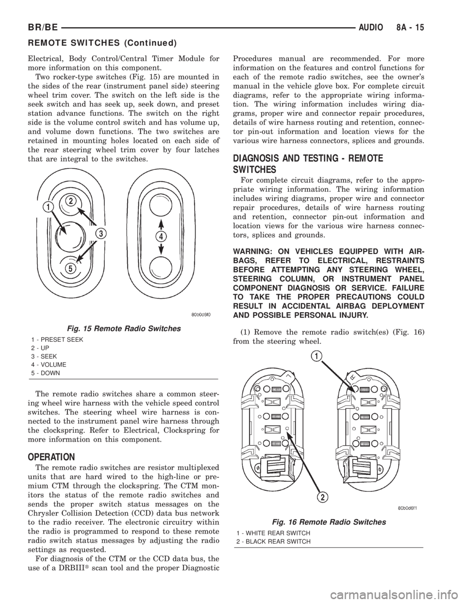
Two rocker-type switches (Fig. 15) are mounted in
the sides of the rear (instrument panel side) steering
wheel trim cover. The switch on the left side is the
seek switch and has seek up, seek down, and preset
station advance functions. The switch on the right
side is the volume control switch and has volume up,
and volume down functions. The two switches are
retained in mounting holes located on each side of
the rear steering wheel trim cover by four latches
that are integral to the switches.
The remote radio switches share a common steer-
ing wheel wire harness with the vehicle speed control
switches. The steering wheel wire harness is con-
nected to the instrument panel wire harness through
the clockspring. Refer to Electrical, Clockspring for
more information on this component.
OPERATION
The remote radio switches are resistor multiplexed
units that are hard wired to the high-line or pre-
mium CTM through the clockspring. The CTM mon-
itors the status of the remote radio switches and
sends the proper switch status messages on the
Chrysler Collision Detection (CCD) data bus network
to the radio receiver. The electronic circuitry within
the radio is programmed to respond to these remote
radio switch status messages by adjusting the radio
settings as requested.
For diagnosis of the CTM or the CCD data bus, the
use of a DRBIIItscan tool and the proper DiagnosticProcedures manual are recommended. For more
information on the features and control functions for
each of the remote radio switches, see the owner's
manual in the vehicle glove box. For complete circuit
diagrams, refer to the appropriate wiring informa-
tion. The wiring information includes wiring dia-
grams, proper wire and connector repair procedures,
details of wire harness routing and retention, connec-
tor pin-out information and location views for the
various wire harness connectors, splices and grounds.
DIAGNOSIS AND TESTING - REMOTE
SWITCHES
For complete circuit diagrams, refer to the appro-
priate wiring information. The wiring information
includes wiring diagrams, proper wire and connector
repair procedures, details of wire harness routing
and retention, connector pin-out information and
location views for the various wire harness connec-
tors, splices and grounds.
WARNING: ON VEHICLES EQUIPPED WITH AIR-
BAGS, REFER TO ELECTRICAL, RESTRAINTS
BEFORE ATTEMPTING ANY STEERING WHEEL,
STEERING COLUMN, OR INSTRUMENT PANEL
COMPONENT DIAGNOSIS OR SERVICE. FAILURE
TO TAKE THE PROPER PRECAUTIONS COULD
RESULT IN ACCIDENTAL AIRBAG DEPLOYMENT
AND POSSIBLE PERSONAL INJURY.
(1) Remove the remote radio switch(es) (Fig. 16)
from the steering wheel.
Fig. 15 Remote Radio Switches
1 - PRESET SEEK
2-UP
3 - SEEK
4 - VOLUME
5 - DOWN
Fig. 16 Remote Radio Switches
1 - WHITE REAR SWITCH
2 - BLACK REAR SWITCH
BR/BEAUDIO 8A - 15
REMOTE SWITCHES (Continued)
Page 369 of 2255
HARD WIRED OUTPUTS
The hard wired outputs of the CTM include the fol-
lowing:
²CCD bus± - high-line/premium version only
²CCD bus+ - high-line/premium version only
²Courtesy lamp switch output - high-line/pre-
mium version only
²Door lock driver - high-line/premium version
only
²Door unlock driver - high-line/premium version
only
²Headlamp relay control - high-line/premium ver-
sion only
²Heated seat relay control - premium version
only
²Horn relay control - high-line/premium version
only
²VTSS indicator driver - high-line/premium ver-
sion only
²Wiper motor relay control
MESSAGING
The high-line/premium CTM uses the following
messages received from other electronic modules over
the CCD data bus:
²Airbag Deploy (ACM)
²Charging System Failure (PCM)
²Engine RPM (PCM)
²System Voltage (PCM)
²Vehicle Speed (PCM)
²Voltage Fault (PCM)
The high-line/premium CTM provides the following
messages to other electronic modules over the CCD
data bus:
²Engine Enable (PCM)
²Radio Seek Up (Radio)
²Radio Seek Down (Radio)
²Radio Volume Up (Radio)
²Radio Volume Down (Radio)
²Preset Scan (Radio)
DIAGNOSIS AND TESTING - CENTRAL TIMER
MODULE
The hard wired inputs to and outputs from the
Central Timer Module (CTM) may be diagnosed and
tested using conventional diagnostic tools and meth-
ods. Refer to the appropriate wiring information. The
wiring information includes wiring diagrams, proper
wire and connector repair procedures, further details
on wire harness routing and retention, as well as
pin-out and location views for the various wire har-
ness connectors, splices and grounds.
However, conventional diagnostic methods may not
prove conclusive in the diagnosis of the high-line/pre-
mium CTM. In order to obtain conclusive testing of
the high-line/premium CTM, the Chrysler CollisionDetection (CCD) data bus network and all of the elec-
tronic modules that provide inputs to or receive out-
puts from the CTM must also be checked. The most
reliable, efficient, and accurate means to diagnose
the high-line/premium CTM, the CCD data bus net-
work, and the electronic modules that provide inputs
to or receive outputs from the high-line/premium
CTM requires the use of a DRBIIItscan tool and the
appropriate diagnostic information. The DRBIIIt
scan tool can provide confirmation that the CCD data
bus network is functional, that all of the electronic
modules are sending and receiving the proper mes-
sages over the CCD data bus, and that the CTM is
receiving the proper hard wired inputs and respond-
ing with the proper hard wired outputs needed to
perform its many functions.
WARNING: ON VEHICLES EQUIPPED WITH AIR-
BAGS, DISABLE THE AIRBAG SYSTEM BEFORE
ATTEMPTING ANY STEERING WHEEL, STEERING
COLUMN, OR INSTRUMENT PANEL COMPONENT
DIAGNOSIS OR SERVICE. DISCONNECT AND ISO-
LATE THE BATTERY NEGATIVE (GROUND) CABLE,
THEN WAIT TWO MINUTES FOR THE AIRBAG SYS-
TEM CAPACITOR TO DISCHARGE BEFORE PER-
FORMING FURTHER DIAGNOSIS OR SERVICE. THIS
IS THE ONLY SURE WAY TO DISABLE THE AIRBAG
SYSTEM. FAILURE TO TAKE THE PROPER PRE-
CAUTIONS COULD RESULT IN ACCIDENTAL AIR-
BAG DEPLOYMENT AND POSSIBLE PERSONAL
INJURY.
NOTE: The following tests may not prove conclu-
sive in the diagnosis of the high-line or premium
versions of the Central Timer Module (CTM). The
most reliable, efficient, and accurate means to diag-
nose the high-line or premium CTM requires the
use of a DRBIIITscan tool and the appropriate diag-
nostic information.
(1) Check the fused B(+) fuse (Fuse 13 - 10
ampere) in the Junction Block (JB). If OK, go to Step
2. If not OK, repair the shorted circuit or component
as required and replace the faulty fuse.
(2) Check for battery voltage at the fused B(+) fuse
(Fuse 13 - 10 ampere) in the JB. If OK, go to Step 3.
If not OK, repair the open fused B(+) circuit between
the JB and the Power Distribution Center (PDC) as
required.
(3) For a base version CTM, check the fused igni-
tion switch output (st-run) fuse (Fuse 11 - 10 ampere)
in the JB. For a high-line/premium version CTM,
check the fused ignition switch output (run-acc) fuse
(Fuse6-25ampere) in the JB. If OK, go to Step 4. If
not OK, repair the shorted circuit or component as
required and replace the faulty fuse.
8E - 4 ELECTRONIC CONTROL MODULESBR/BE
CENTRAL TIMER MODULE (Continued)
Page 376 of 2255
DIAGNOSIS AND TESTING - CCD DATA BUS
CCD BUS FAILURE
The CCD data bus can be monitored using the
DRBIIItscan tool. However, it is possible for the
data bus to pass all tests since the voltage parame-
ters will be in ªrangeª and false signals are being
sent. There are essentially 12 ªhard failuresª that
can occur with the CCD data bus:
²Bus Shorted to Battery
²Bus Shorted to 5 Volts
²Bus Shorted to Ground
²Bus (+) Shorted to Bus (±)
²Bus (±) and Bus (+) Open
²Bus (+) Open
²Bus (±) Open
²No Bus Bias
²Bus Bias Level Too High
²Bus Bias Level Too Low
²No Bus Termination
²Not Receiving Bus Messages Correctly
Refer to the appropriate diagnostic information for
details on how to diagnose these faults using a
DRBIIItscan tool.
BUS FAILURE VISUAL SYMPTOM DIAGNOSIS
The following visible symptoms or customer com-
plaints, alone or in combination, may indicate a CCD
data bus failure:
²Airbag Indicator and Malfunction Indicator
Lamp (MIL) Illuminated
²Instrument Cluster Gauges (All) Inoperative
²No Compass Mini-Trip Computer (CMTC) Oper-
ation (if equipped)
CONTROLLER ANTILOCK
BRAKE
DESCRIPTION
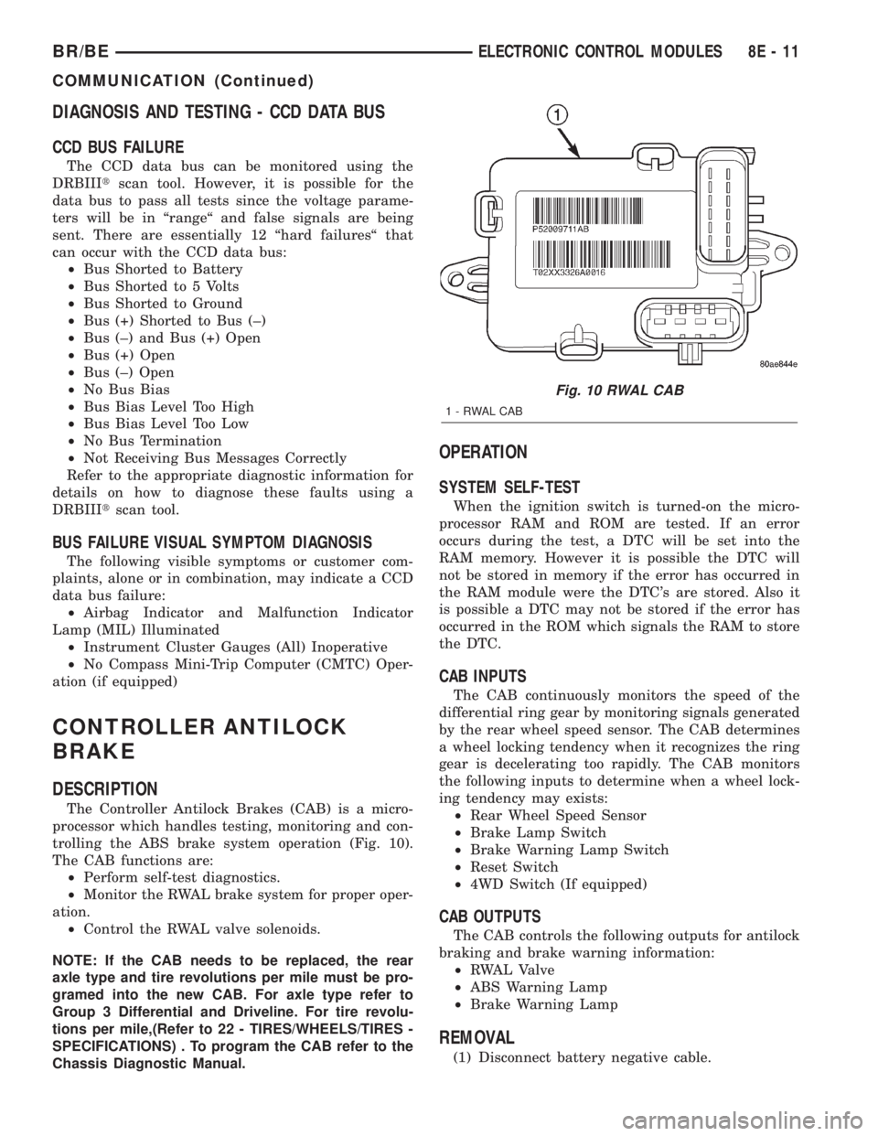
The Controller Antilock Brakes (CAB) is a micro-
processor which handles testing, monitoring and con-
trolling the ABS brake system operation (Fig. 10).
The CAB functions are:
²Perform self-test diagnostics.
²Monitor the RWAL brake system for proper oper-
ation.
²Control the RWAL valve solenoids.
NOTE: If the CAB needs to be replaced, the rear
axle type and tire revolutions per mile must be pro-
gramed into the new CAB. For axle type refer to
Group 3 Differential and Driveline. For tire revolu-
tions per mile,(Refer to 22 - TIRES/WHEELS/TIRES -
SPECIFICATIONS) . To program the CAB refer to the
Chassis Diagnostic Manual.
OPERATION
SYSTEM SELF-TEST
When the ignition switch is turned-on the micro-
processor RAM and ROM are tested. If an error
occurs during the test, a DTC will be set into the
RAM memory. However it is possible the DTC will
not be stored in memory if the error has occurred in
the RAM module were the DTC's are stored. Also it
is possible a DTC may not be stored if the error has
occurred in the ROM which signals the RAM to store
the DTC.
CAB INPUTS
The CAB continuously monitors the speed of the
differential ring gear by monitoring signals generated
by the rear wheel speed sensor. The CAB determines
a wheel locking tendency when it recognizes the ring
gear is decelerating too rapidly. The CAB monitors
the following inputs to determine when a wheel lock-
ing tendency may exists:
²Rear Wheel Speed Sensor
²Brake Lamp Switch
²Brake Warning Lamp Switch
²Reset Switch
²4WD Switch (If equipped)
CAB OUTPUTS
The CAB controls the following outputs for antilock
braking and brake warning information:
²RWAL Valve
²ABS Warning Lamp
²Brake Warning Lamp
REMOVAL
(1) Disconnect battery negative cable.
Fig. 10 RWAL CAB
1-RWALCAB
BR/BEELECTRONIC CONTROL MODULES 8E - 11
COMMUNICATION (Continued)
Page 380 of 2255
POWERTRAIN CONTROL
MODULE
DESCRIPTION
DESCRIPTION - PCM
The Powertrain Control Module (PCM) is located
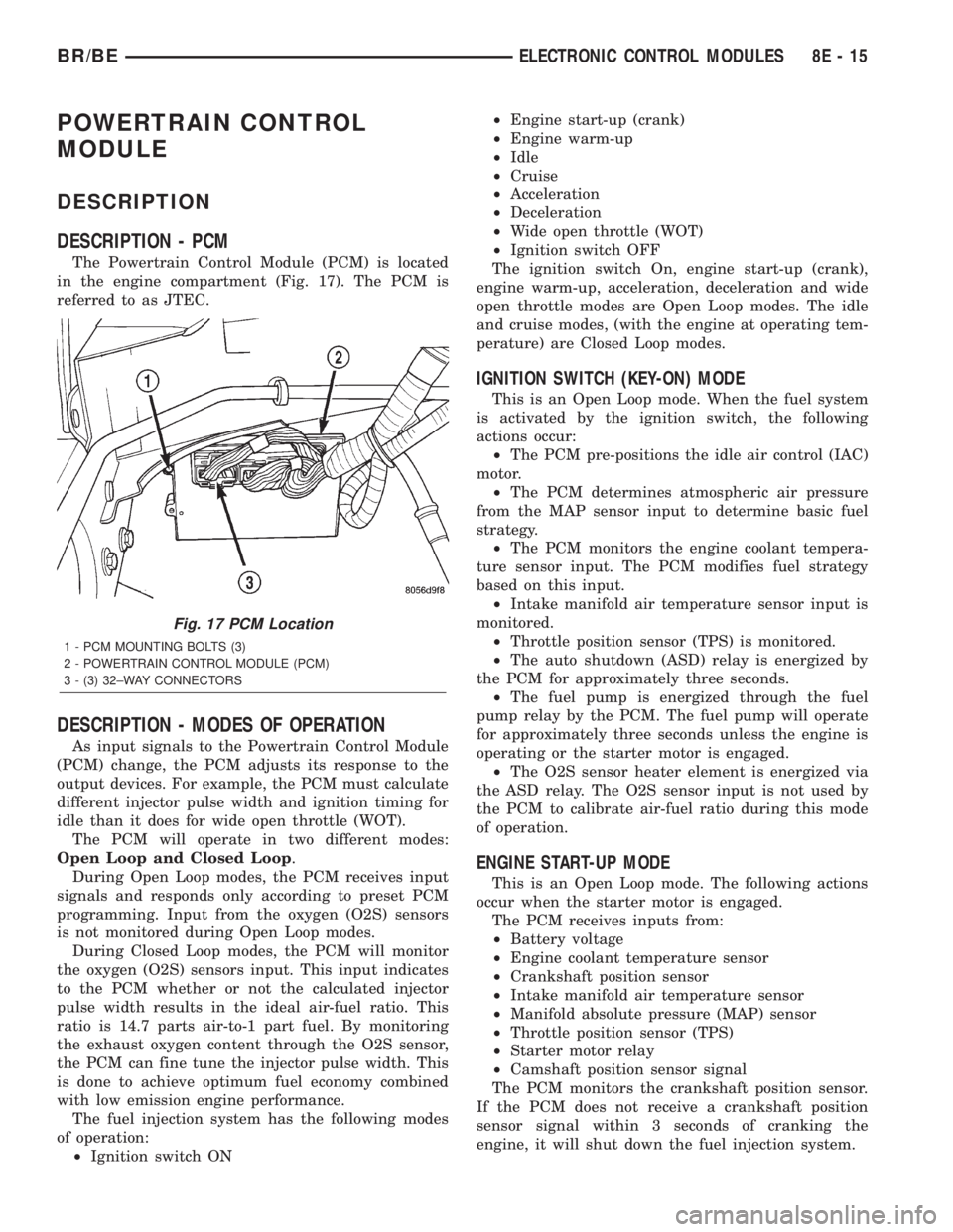
in the engine compartment (Fig. 17). The PCM is
referred to as JTEC.
DESCRIPTION - MODES OF OPERATION
As input signals to the Powertrain Control Module
(PCM) change, the PCM adjusts its response to the
output devices. For example, the PCM must calculate
different injector pulse width and ignition timing for
idle than it does for wide open throttle (WOT).
The PCM will operate in two different modes:
Open Loop and Closed Loop.
During Open Loop modes, the PCM receives input
signals and responds only according to preset PCM
programming. Input from the oxygen (O2S) sensors
is not monitored during Open Loop modes.
During Closed Loop modes, the PCM will monitor
the oxygen (O2S) sensors input. This input indicates
to the PCM whether or not the calculated injector
pulse width results in the ideal air-fuel ratio. This
ratio is 14.7 parts air-to-1 part fuel. By monitoring
the exhaust oxygen content through the O2S sensor,
the PCM can fine tune the injector pulse width. This
is done to achieve optimum fuel economy combined
with low emission engine performance.
The fuel injection system has the following modes
of operation:
²Ignition switch ON²Engine start-up (crank)
²Engine warm-up
²Idle
²Cruise
²Acceleration
²Deceleration
²Wide open throttle (WOT)
²Ignition switch OFF
The ignition switch On, engine start-up (crank),
engine warm-up, acceleration, deceleration and wide
open throttle modes are Open Loop modes. The idle
and cruise modes, (with the engine at operating tem-
perature) are Closed Loop modes.
IGNITION SWITCH (KEY-ON) MODE
This is an Open Loop mode. When the fuel system
is activated by the ignition switch, the following
actions occur:
²The PCM pre-positions the idle air control (IAC)
motor.
²The PCM determines atmospheric air pressure
from the MAP sensor input to determine basic fuel
strategy.
²The PCM monitors the engine coolant tempera-
ture sensor input. The PCM modifies fuel strategy
based on this input.
²Intake manifold air temperature sensor input is
monitored.
²Throttle position sensor (TPS) is monitored.
²The auto shutdown (ASD) relay is energized by
the PCM for approximately three seconds.
²The fuel pump is energized through the fuel
pump relay by the PCM. The fuel pump will operate
for approximately three seconds unless the engine is
operating or the starter motor is engaged.
²The O2S sensor heater element is energized via
the ASD relay. The O2S sensor input is not used by
the PCM to calibrate air-fuel ratio during this mode
of operation.
ENGINE START-UP MODE
This is an Open Loop mode. The following actions
occur when the starter motor is engaged.
The PCM receives inputs from:
²Battery voltage
²Engine coolant temperature sensor
²Crankshaft position sensor
²Intake manifold air temperature sensor
²Manifold absolute pressure (MAP) sensor
²Throttle position sensor (TPS)
²Starter motor relay
²Camshaft position sensor signal
The PCM monitors the crankshaft position sensor.
If the PCM does not receive a crankshaft position
sensor signal within 3 seconds of cranking the
engine, it will shut down the fuel injection system.
Fig. 17 PCM Location
1 - PCM MOUNTING BOLTS (3)
2 - POWERTRAIN CONTROL MODULE (PCM)
3 - (3) 32±WAY CONNECTORS
BR/BEELECTRONIC CONTROL MODULES 8E - 15
Page 481 of 2255
INSTRUMENT CLUSTER
DESCRIPTION
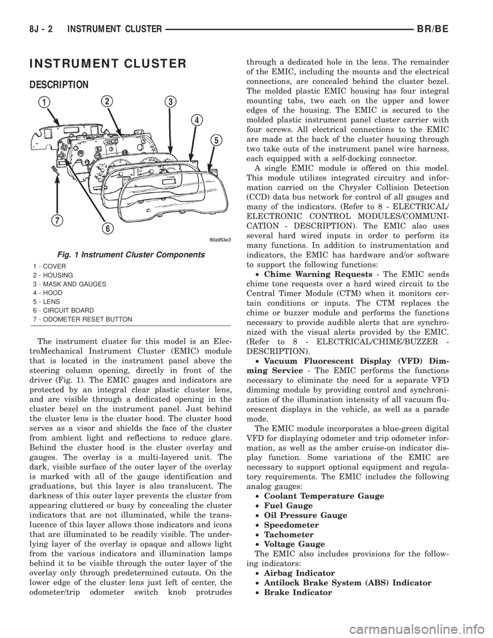
The instrument cluster for this model is an Elec-
troMechanical Instrument Cluster (EMIC) module
that is located in the instrument panel above the
steering column opening, directly in front of the
driver (Fig. 1). The EMIC gauges and indicators are
protected by an integral clear plastic cluster lens,
and are visible through a dedicated opening in the
cluster bezel on the instrument panel. Just behind
the cluster lens is the cluster hood. The cluster hood
serves as a visor and shields the face of the cluster
from ambient light and reflections to reduce glare.
Behind the cluster hood is the cluster overlay and
gauges. The overlay is a multi-layered unit. The
dark, visible surface of the outer layer of the overlay
is marked with all of the gauge identification and
graduations, but this layer is also translucent. The
darkness of this outer layer prevents the cluster from
appearing cluttered or busy by concealing the cluster
indicators that are not illuminated, while the trans-
lucence of this layer allows those indicators and icons
that are illuminated to be readily visible. The under-
lying layer of the overlay is opaque and allows light
from the various indicators and illumination lamps
behind it to be visible through the outer layer of the
overlay only through predetermined cutouts. On the
lower edge of the cluster lens just left of center, the
odometer/trip odometer switch knob protrudesthrough a dedicated hole in the lens. The remainder
of the EMIC, including the mounts and the electrical
connections, are concealed behind the cluster bezel.
The molded plastic EMIC housing has four integral
mounting tabs, two each on the upper and lower
edges of the housing. The EMIC is secured to the
molded plastic instrument panel cluster carrier with
four screws. All electrical connections to the EMIC
are made at the back of the cluster housing through
two take outs of the instrument panel wire harness,
each equipped with a self-docking connector.
A single EMIC module is offered on this model.
This module utilizes integrated circuitry and infor-
mation carried on the Chrysler Collision Detection
(CCD) data bus network for control of all gauges and
many of the indicators. (Refer to 8 - ELECTRICAL/
ELECTRONIC CONTROL MODULES/COMMUNI-
CATION - DESCRIPTION). The EMIC also uses
several hard wired inputs in order to perform its
many functions. In addition to instrumentation and
indicators, the EMIC has hardware and/or software
to support the following functions:
²Chime Warning Requests- The EMIC sends
chime tone requests over a hard wired circuit to the
Central Timer Module (CTM) when it monitors cer-
tain conditions or inputs. The CTM replaces the
chime or buzzer module and performs the functions
necessary to provide audible alerts that are synchro-
nized with the visual alerts provided by the EMIC.
(Refer to 8 - ELECTRICAL/CHIME/BUZZER -
DESCRIPTION).
²Vacuum Fluorescent Display (VFD) Dim-
ming Service- The EMIC performs the functions
necessary to eliminate the need for a separate VFD
dimming module by providing control and synchroni-
zation of the illumination intensity of all vacuum flu-
orescent displays in the vehicle, as well as a parade
mode.
The EMIC module incorporates a blue-green digital
VFD for displaying odometer and trip odometer infor-
mation, as well as the amber cruise-on indicator dis-
play function. Some variations of the EMIC are
necessary to support optional equipment and regula-
tory requirements. The EMIC includes the following
analog gauges:
²Coolant Temperature Gauge
²Fuel Gauge
²Oil Pressure Gauge
²Speedometer
²Tachometer
²Voltage Gauge
The EMIC also includes provisions for the follow-
ing indicators:
²Airbag Indicator
²Antilock Brake System (ABS) Indicator
²Brake Indicator
Fig. 1 Instrument Cluster Components
1 - COVER
2 - HOUSING
3 - MASK AND GAUGES
4 - HOOD
5 - LENS
6 - CIRCUIT BOARD
7 - ODOMETER RESET BUTTON
8J - 2 INSTRUMENT CLUSTERBR/BE
Page 483 of 2255
The EMIC circuitry operates on battery current
received through a fused B(+) fuse in the Junction
Block (JB) on a non-switched fused B(+) circuit, and
on battery current received through a fused ignition
switch output (st-run) fuse in the JB on a fused igni-
tion switch output (st-run) circuit. This arrangement
allows the EMIC to provide some features regardless
of the ignition switch position, while other features
will operate only with the ignition switch in the Start
or On positions. The EMIC circuitry is grounded
through two separate ground circuits located in one
of the two instrument cluster connectors and take
outs of the instrument panel wire harness. One
ground circuit receives ground through a take out
with an eyelet terminal connector of the instrument
panel wire harness that is secured by a nut to a
ground stud located on the left instrument panel end
bracket, while the other ground circuit receives
ground through a take out with an eyelet terminal
connector of the instrument panel wire harness that
is secured by a nut to a ground stud located on the
back of the instrument panel armature above the
inboard side of the instrument panel steering column
opening.
The EMIC also has a self-diagnostic actuator test
capability, which will test each of the CCD bus mes-
sage-controlled functions of the cluster by lighting
the appropriate indicators and positioning the gauge
needles at several predetermined locations on the
gauge faces in a prescribed sequence. (Refer to 8 -
ELECTRICAL/INSTRUMENT CLUSTER - DIAGNO-
SIS AND TESTING). See the owner's manual in the
vehicle glove box for more information on the fea-
tures, use and operation of the EMIC.
GAUGES
All gauges receive battery current through the
EMIC circuitry when the ignition switch is in the On
or Start positions. With the ignition switch in the Off
position battery current is not supplied to any
gauges, and the EMIC circuitry is programmed to
move all of the gauge needles back to the low end of
their respective scales. Therefore, the gauges do not
accurately indicate any vehicle condition unless the
ignition switch is in the On or Start positions. All of
the EMIC gauges, except the odometer, are air core
magnetic units. Two fixed electromagnetic coils are
located within each gauge. These coils are wrapped
at right angles to each other around a movable per-
manent magnet. The movable magnet is suspended
within the coils on one end of a pivot shaft, while the
gauge needle is attached to the other end of the
shaft. One of the coils has a fixed current flowing
through it to maintain a constant magnetic field
strength. Current flow through the second coil
changes, which causes changes in its magnetic fieldstrength. The current flowing through the second coil
is changed by the EMIC circuitry in response to mes-
sages received over the CCD data bus. The gauge
needle moves as the movable permanent magnet
aligns itself to the changing magnetic fields created
around it by the electromagnets.
The gauges are diagnosed using the EMIC self-di-
agnostic actuator test. (Refer to 8 - ELECTRICAL/
INSTRUMENT CLUSTER - DIAGNOSIS AND
TESTING). Proper testing of the CCD data bus and
the data bus message inputs to the EMIC that con-
trol each gauge require the use of a DRBIIItscan
tool. Refer to the appropriate diagnostic information.
Specific operation details for each gauge may be
found elsewhere in this service manual.
VACUUM-FLUORESCENT DISPLAY
The Vacuum-Fluorescent Display (VFD) module is
soldered to the EMIC circuit board. The display is
active with the ignition switch in the On or Start
positions, and inactive when the ignition switch is in
any other position. The VFD has several display
capabilities including odometer, trip odometer, and
an amber ªCRUISEº indication whenever the
optional speed control system is turned On. The
cruise indicator function of the VFD is automatically
enabled or disabled by the EMIC circuitry based
upon whether the vehicle is equipped with the speed
control option. An odometer/trip odometer switch on
the EMIC circuit board is used to control several of
the display modes. This switch is actuated manually
by depressing the odometer/trip odometer switch
knob that extends through the lower edge of the clus-
ter lens, just right of center. Actuating this switch
momentarily with the ignition switch in the On posi-
tion will toggle the VFD between the odometer and
trip odometer modes. The word ªTRIPº will also
appear in blue-green text when the VFD trip odome-
ter mode is active. Depressing the switch button for
about two seconds while the VFD is in the trip odom-
eter mode will reset the trip odometer value to zero.
Holding this switch depressed while turning the igni-
tion switch from the Off position to the On position
will activate the EMIC self-diagnostic actuator test.
The EMIC will automatically flash the odometer or
trip odometer information on and off if there is a loss
of CCD data bus communication. The VFD will also
display various information used in several diagnos-
tic procedures. Refer to the appropriate diagnostic
information for additional details on this VFD func-
tion.
The VFD is diagnosed using the EMIC self-diag-
nostic actuator test. (Refer to 8 - ELECTRICAL/IN-
STRUMENT CLUSTER - DIAGNOSIS AND
TESTING). Proper testing of the CCD data bus and
the data bus message inputs to the EMIC that con-
8J - 4 INSTRUMENT CLUSTERBR/BE
INSTRUMENT CLUSTER (Continued)
Page 487 of 2255
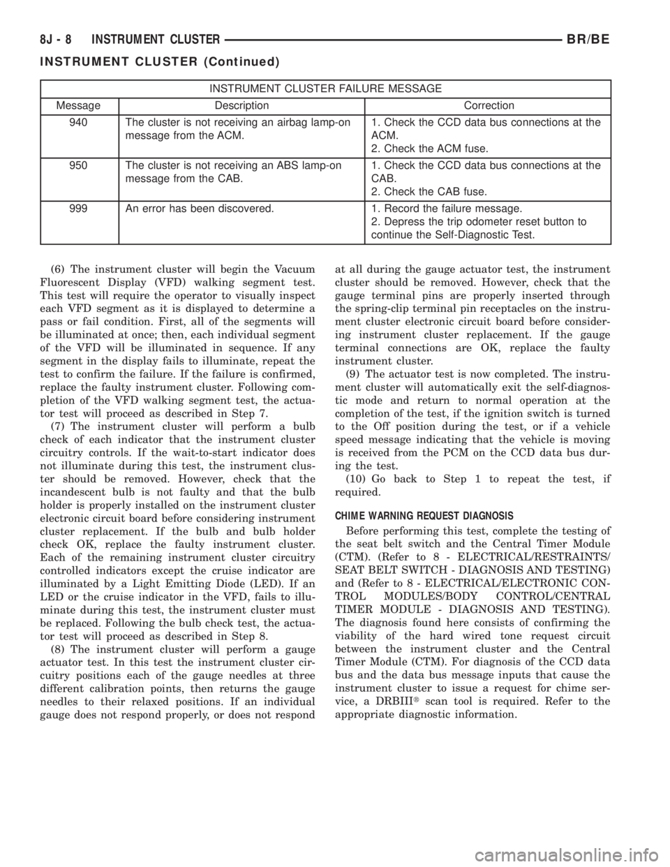
INSTRUMENT CLUSTER FAILURE MESSAGE
Message Description Correction
940 The cluster is not receiving an airbag lamp-on
message from the ACM.1. Check the CCD data bus connections at the
ACM.
2. Check the ACM fuse.
950 The cluster is not receiving an ABS lamp-on
message from the CAB.1. Check the CCD data bus connections at the
CAB.
2. Check the CAB fuse.
999 An error has been discovered. 1. Record the failure message.
2. Depress the trip odometer reset button to
continue the Self-Diagnostic Test.
(6) The instrument cluster will begin the Vacuum
Fluorescent Display (VFD) walking segment test.
This test will require the operator to visually inspect
each VFD segment as it is displayed to determine a
pass or fail condition. First, all of the segments will
be illuminated at once; then, each individual segment
of the VFD will be illuminated in sequence. If any
segment in the display fails to illuminate, repeat the
test to confirm the failure. If the failure is confirmed,
replace the faulty instrument cluster. Following com-
pletion of the VFD walking segment test, the actua-
tor test will proceed as described in Step 7.
(7) The instrument cluster will perform a bulb
check of each indicator that the instrument cluster
circuitry controls. If the wait-to-start indicator does
not illuminate during this test, the instrument clus-
ter should be removed. However, check that the
incandescent bulb is not faulty and that the bulb
holder is properly installed on the instrument cluster
electronic circuit board before considering instrument
cluster replacement. If the bulb and bulb holder
check OK, replace the faulty instrument cluster.
Each of the remaining instrument cluster circuitry
controlled indicators except the cruise indicator are
illuminated by a Light Emitting Diode (LED). If an
LED or the cruise indicator in the VFD, fails to illu-
minate during this test, the instrument cluster must
be replaced. Following the bulb check test, the actua-
tor test will proceed as described in Step 8.
(8) The instrument cluster will perform a gauge
actuator test. In this test the instrument cluster cir-
cuitry positions each of the gauge needles at three
different calibration points, then returns the gauge
needles to their relaxed positions. If an individual
gauge does not respond properly, or does not respondat all during the gauge actuator test, the instrument
cluster should be removed. However, check that the
gauge terminal pins are properly inserted through
the spring-clip terminal pin receptacles on the instru-
ment cluster electronic circuit board before consider-
ing instrument cluster replacement. If the gauge
terminal connections are OK, replace the faulty
instrument cluster.
(9) The actuator test is now completed. The instru-
ment cluster will automatically exit the self-diagnos-
tic mode and return to normal operation at the
completion of the test, if the ignition switch is turned
to the Off position during the test, or if a vehicle
speed message indicating that the vehicle is moving
is received from the PCM on the CCD data bus dur-
ing the test.
(10) Go back to Step 1 to repeat the test, if
required.
CHIME WARNING REQUEST DIAGNOSIS
Before performing this test, complete the testing of
the seat belt switch and the Central Timer Module
(CTM). (Refer to 8 - ELECTRICAL/RESTRAINTS/
SEAT BELT SWITCH - DIAGNOSIS AND TESTING)
and (Refer to 8 - ELECTRICAL/ELECTRONIC CON-
TROL MODULES/BODY CONTROL/CENTRAL
TIMER MODULE - DIAGNOSIS AND TESTING).
The diagnosis found here consists of confirming the
viability of the hard wired tone request circuit
between the instrument cluster and the Central
Timer Module (CTM). For diagnosis of the CCD data
bus and the data bus message inputs that cause the
instrument cluster to issue a request for chime ser-
vice, a DRBIIItscan tool is required. Refer to the
appropriate diagnostic information.
8J - 8 INSTRUMENT CLUSTERBR/BE
INSTRUMENT CLUSTER (Continued)