Diagram section DODGE RAM 2002 Service User Guide
[x] Cancel search | Manufacturer: DODGE, Model Year: 2002, Model line: RAM, Model: DODGE RAM 2002Pages: 2255, PDF Size: 62.07 MB
Page 565 of 2255
AMBIENT TEMP SENSOR
DESCRIPTION
Ambient air temperature is monitored by the com-
pass mini-trip computer module through the ambient
temperature sensor. The ambient temperature sensor
is a variable resistor mounted to a bracket that is
secured with a screw to the underside of the hood
panel near the hood latch striker in the engine com-
partment (Fig. 8).
For complete circuit diagrams, refer toOverhead
Consolein the Contents of Wiring Diagrams. The
ambient temperature sensor cannot be adjusted or
repaired and, if faulty or damaged, it must be
replaced.
OPERATION
The ambient temperature sensor is a variable
resistor that operates on a five-volt reference signal
sent to it by the compass mini-trip computer module.
The resistance in the sensor changes as temperature
changes, changing the return circuit voltage to the
compass mini-trip computer module. Based upon the
resistance in the sensor, the compass mini-trip com-
puter module senses a specific voltage on the return
circuit, which it is programmed to correspond to a
specific temperature.
DIAGNOSIS AND TESTING - AMBIENT
TEMPERATURE SENSOR
The thermometer function is supported by the
ambient temperature sensor, a wiring circuit, and a
portion of the compass mini-trip computer module. If
any portion of the ambient temperature sensor cir-
cuit fails, the compass/thermometer display function
will self-diagnose the circuit. If 55É C (131É F)
appears in the display, the sensor is being exposed to
temperatures above 55É C (131É F), or the sensor cir-
cuit is shorted. If ±40É C (±40É F) appears in the dis-
play, the sensor is being exposed to temperatures
below ±40É C (±40É F), or the sensor circuit is open.
The ambient temperature sensor circuit can also be
diagnosed using the following Sensor Test, and Sen-
sor Circuit Test. If the temperature sensor and cir-
cuit are confirmed to be OK, but the temperature
display is inoperative or incorrect, refer toDiagnosis
and Testing the Compass Mini-Trip Computer.
For complete circuit diagrams, refer toWiring Dia-
grams.
SENSOR TEST
(1) Turn the ignition switch to the Off position.
Disconnect and isolate the battery negative cable.
Disconnect the ambient temperature sensor wire har-
ness connector.(2) Measure the resistance of the ambient temper-
ature sensor. At ±40É C (±40É F), the sensor resis-
tance is 336 kilohms. At 55É C (131É F), the sensor
resistance is 2.488 kilohms. The sensor resistance
should read between these two values. If OK, refer to
theSensor Circuit Test below. If not OK, replace
the faulty ambient temperature sensor.
SENSOR CIRCUIT TEST
(1) Turn the ignition switch to the Off position.
Disconnect and isolate the battery negative cable.
Disconnect the ambient temperature sensor wire har-
ness connector and the overhead console wire har-
ness connector.
(2) Connect a jumper wire between the two termi-
nals in the body half of the ambient temperature sen-
sor wire harness connector.
(3) Check for continuity between the sensor return
circuit and the ambient temperature sensor signal
circuit cavities of the roof wire harness overhead con-
sole connector. There should be continuity. If OK, go
to Step 4. If not OK, repair the open sensor return
circuit or ambient temperature sensor signal circuit
to the ambient temperature sensor as required.
(4) Remove the jumper wire from the body half of
the ambient temperature sensor wire harness con-
nector. Check for continuity between the sensor
return circuit cavity of the roof wire harness over-
head console connector and a good ground. There
should be no continuity. If OK, go to Step 5. If not
OK, repair the shorted sensor return circuit as
required.
(5) Check for continuity between the ambient tem-
perature sensor signal circuit cavity of the roof wire
harness overhead console connector and a good
ground. There should be no continuity. If OK, refer to
Diagnosis and Testing the Compass Mini-Trip
Computerin this section. If not OK, repair the
shorted ambient temperature sensor signal circuit as
required.
REMOVAL
(1) Disconnect and isolate the battery negative
cable.
(2) Locate the ambient temperature sensor, on the
underside of the hood near the hood latch striker
(Fig. 8).
(3) Disconnect the wire harness connector from the
ambient temperature sensor connector receptacle.
(4) Remove the one screw that secures the ambient
temperature sensor bracket to the inner hood rein-
forcement.
(5) Remove the ambient temperature sensor from
the inner hood reinforcement.
8M - 12 MESSAGE SYSTEMSBR/BE
Page 587 of 2255
PASSENGER POWER SEAT
SWITCH
DESCRIPTION
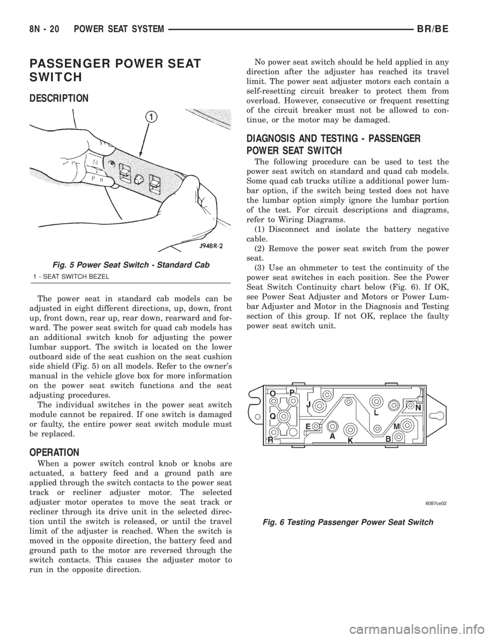
The power seat in standard cab models can be
adjusted in eight different directions, up, down, front
up, front down, rear up, rear down, rearward and for-
ward. The power seat switch for quad cab models has
an additional switch knob for adjusting the power
lumbar support. The switch is located on the lower
outboard side of the seat cushion on the seat cushion
side shield (Fig. 5) on all models. Refer to the owner's
manual in the vehicle glove box for more information
on the power seat switch functions and the seat
adjusting procedures.
The individual switches in the power seat switch
module cannot be repaired. If one switch is damaged
or faulty, the entire power seat switch module must
be replaced.
OPERATION
When a power switch control knob or knobs are
actuated, a battery feed and a ground path are
applied through the switch contacts to the power seat
track or recliner adjuster motor. The selected
adjuster motor operates to move the seat track or
recliner through its drive unit in the selected direc-
tion until the switch is released, or until the travel
limit of the adjuster is reached. When the switch is
moved in the opposite direction, the battery feed and
ground path to the motor are reversed through the
switch contacts. This causes the adjuster motor to
run in the opposite direction.No power seat switch should be held applied in any
direction after the adjuster has reached its travel
limit. The power seat adjuster motors each contain a
self-resetting circuit breaker to protect them from
overload. However, consecutive or frequent resetting
of the circuit breaker must not be allowed to con-
tinue, or the motor may be damaged.
DIAGNOSIS AND TESTING - PASSENGER
POWER SEAT SWITCH
The following procedure can be used to test the
power seat switch on standard and quad cab models.
Some quad cab trucks utilize a additional power lum-
bar option, if the switch being tested does not have
the lumbar option simply ignore the lumbar portion
of the test. For circuit descriptions and diagrams,
refer to Wiring Diagrams.
(1) Disconnect and isolate the battery negative
cable.
(2) Remove the power seat switch from the power
seat.
(3) Use an ohmmeter to test the continuity of the
power seat switches in each position. See the Power
Seat Switch Continuity chart below (Fig. 6). If OK,
see Power Seat Adjuster and Motors or Power Lum-
bar Adjuster and Motor in the Diagnosis and Testing
section of this group. If not OK, replace the faulty
power seat switch unit.
Fig. 5 Power Seat Switch - Standard Cab
1 - SEAT SWITCH BEZEL
Fig. 6 Testing Passenger Power Seat Switch
8N - 20 POWER SEAT SYSTEMBR/BE
Page 589 of 2255
Each motor contains a self-resetting circuit breaker
to protect it from overload. Consecutive or frequent
resetting of the circuit breakers must not be allowed
to continue, or the motors may be damaged.
The power seat adjuster and motors cannot be
repaired, and are serviced only as a complete unit. If
any component in this unit is faulty or damaged, the
entire power seat adjuster and motors assembly must
be replaced.
OPERATION
When a power seat switch is actuated, a battery
feed and a ground path are applied through the
power seat switch contacts to the appropriate motor
or motors. The motor and drive unit operate to move
the seat in the selected direction until the switch is
released, or until the travel limit of the power seat
track is reached. When the switch is moved in the
opposite direction, the battery feed and ground path
to the motor is reversed through the switch contacts.
This causes the motor to run in the opposite direc-
tion.
DIAGNOSIS AND TESTING - POWER SEAT
TRACK
For complete power seat circuit descriptions and
diagrams, refer to Wiring Diagrams.
Operate the power seat switch to move all three
seat motors in each direction. The seat should move
in each of the selected directions. If the power seat
track fails to operate in only one direction, move the
seat track a short distance in the opposite direction
and test again to be certain that the track is not at
its travel limit. If the power seat track still fails to
operate in only one direction, refer to Diagnosis and
Testing of the Power Seat Switch in this section. If
the power seat track fails to operate in more than
one direction, proceed as follows:
(1) Check the power seat fuse in the power distri-
bution center. If OK, go to Step 2. If not OK, replace
the faulty fuse.
(2) Remove the power seat switch from the seat.
Check for battery voltage at the fused B(+) circuit
cavity of the power seat switch wire harness connec-
tor. If OK, go to Step 3. If not OK, repair the open
circuit to the power distribution center as required.(3) Check for continuity between the ground cir-
cuit cavity of the power seat switch wire harness con-
nector and a good ground. There should be
continuity. If OK, go to Step 4. If not OK, repair the
open circuit to ground as required.
(4) Test the power seat switch as described in this
group. If the switch tests OK, check the wire harness
between the power seat switch and the motor for
shorts or opens. If the circuits check OK, replace the
faulty power seat track (adjuster) assembly. If the
circuits are not OK, repair the wire harness as
required.
REMOVAL
(1) Disconnect and isolate the battery negative
cable.
(2) Remove the seat, power seat track from the
vehicle as a unit (Refer to 23 - BODY/SEATS/SEAT -
REMOVAL).
(3) Unplug the power seat wire harness connectors
at each of the three power seat motors.
(4) Release the power seat wire harness retainers
from the seat track.
(5) Remove the fasteners that secure the center
seat cushion section to the brackets on the power
seat track.
(6) Remove the screws that secure the power seat
track assembly to the seat cushion frame.
(7) Remove the power seat track assembly from
the seat cushion frame.
INSTALLATION
(1) Position the power seat track assembly on the
seat cushion frame.
(2) Install the fasteners that secure the center seat
cushion section to the brackets on the power seat
adjuster.
(3) Install the screws that secure the power seat
track assembly to the seat cushion frame.
(4) Connect the power seat wire harness connec-
tors at each of the three power seat motors.
(5) Install the power seat wire harness retainers
on the seat track assembly.
(6) Install the seat, power seat track as a unit
(Refer to 23 - BODY/SEATS/SEAT - INSTALLA-
TION).
(7) Connect the battery negative cable.
8N - 22 POWER SEAT SYSTEMBR/BE
POWER SEAT TRACK (Continued)
Page 664 of 2255
8W-01 WIRING DIAGRAM INFORMATION
TABLE OF CONTENTS
page page
WIRING DIAGRAM INFORMATION
DESCRIPTION
DESCRIPTION - HOW TO USE WIRING
DIAGRAMS...........................1
DESCRIPTION - CIRCUIT INFORMATION....4
DESCRIPTION - CIRCUIT FUNCTIONS......4
DESCRIPTION - SECTION IDENTIFICATION
AND INFORMATION....................6
DESCRIPTION - CONNECTOR, GROUND
AND SPLICE INFORMATION..............6
WARNINGS - GENERAL...................7
DIAGNOSIS AND TESTING - WIRING
HARNESS............................7
STANDARD PROCEDURE
STANDARD PROCEDURE -
ELECTROSTATIC DISCHARGE (ESD)
SENSITIVE DEVICES...................8
STANDARD PROCEDURE - TESTING OF
VOLTAGE POTENTIAL...................8
STANDARD PROCEDURE - TESTING FOR
CONTINUITY..........................9STANDARD PROCEDURE - TESTING FOR A
SHORT TO GROUND...................9
STANDARD PROCEDURE - TESTING FOR A
SHORT TO GROUND ON FUSES
POWERING SEVERAL LOADS............9
STANDARD PROCEDURE - TESTING FOR A
VOLTAGE DROP.......................9
SPECIAL TOOLS
WIRING/TERMINAL.....................9
CONNECTOR
REMOVAL.............................10
INSTALLATION.........................10
DIODE
REMOVAL.............................13
INSTALLATION.........................13
TERMINAL
REMOVAL.............................13
INSTALLATION.........................13
WIRE
STANDARD PROCEDURE - WIRE SPLICING . . 13
WIRING DIAGRAM
INFORMATION
DESCRIPTION
DESCRIPTION - HOW TO USE WIRING
DIAGRAMS
DaimlerChrysler Corporation wiring diagrams are
designed to provide information regarding the vehi-
cles wiring content. In order to effectively use the
wiring diagrams to diagnose and repair
DaimlerChrysler Corporation vehicles, it is important
to understand all of their features and characteris-
tics.
Diagrams are arranged such that the power (B+)
side of the circuit is placed near the top of the page,
and the ground (B-) side of the circuit is placed near
the bottom of the page (Fig. 1).All switches, components, and modules are shown
in the at rest position with the doors closed and the
key removed from the ignition (Fig. 2).
Components are shown two ways. A solid line
around a component indicates that the component is
complete. A dashed line around the component indi-
cates that the component is being shown is not com-
plete. Incomplete components have a reference
number to indicate the page where the component is
shown complete.
It is important to realize that no attempt is made
on the diagrams to represent components and wiring
as they appear on the vehicle. For example, a short
piece of wire is treated the same as a long one. In
addition, switches and other components are shown
as simply as possible, with regard to function only.
BR/BE8W-01 WIRING DIAGRAM INFORMATION 8W - 01 - 1
Page 669 of 2255
DESCRIPTION - SECTION IDENTIFICATION AND
INFORMATION
The wiring diagrams are grouped into individual
sections. If a component is most likely found in a par-
ticular group, it will be shown complete (all wires,
connectors, and pins) within that group. For exam-
ple, the Auto Shutdown Relay is most likely to be
found in Group 30, so it is shown there complete. It
can, however, be shown partially in another group if
it contains some associated wiring.
Splice diagrams in Section 8W-70 show the entire
splice and provide references to other sections the
splices serves. Section 8W-70 only contains splice dia-
grams that are not shown in their entirety some-
where else in the wiring diagrams.
Section 8W-80 shows each connector and the cir-
cuits involved with that connector. The connectors
are identified using the name/number on the dia-
gram pages.
WIRING SECTION CHART
GROUP TOPIC
8W-01 thru
8W-09General information and Diagram
Overview
8W-10 thru
8W-19Main Sources of Power and
Vehicle Grounding
8W-20 thru
8W-29Starting and Charging
8W-30 thru
8W-39Powertrain/Drivetrain Systems
GROUP TOPIC
8W-40 thru
8W-49Body Electrical items and A/C
8W-50 thru
8W-59Exterior Lighting, Wipers and
Trailer Tow
8W-60 thru
8W-69Power Accessories
8W-70 Splice Information
8W-80 Connector Pin Outs
8W-91 Connector, Ground and Splice
Locations
DESCRIPTION - CONNECTOR, GROUND AND
SPLICE INFORMATION
CAUTION: Not all connectors are serviced. Some
connectors are serviced only with a harness. A typ-
ical example might be the Supplemental Restraint
System connectors. Always check parts availability
before attempting a repair.
IDENTIFICATION
In-line connectors are identified by a number, as
follows:
²In-line connectors located in the engine compart-
ment are C100 series numbers
²In-line connectors located in the Instrument
Panel area are C200 series numbers.
²In-line connectors located in the body are C300
series numbers.
²Jumper harness connectors are C400 series
numbers.
²Grounds and ground connectors are identified
with a ªGº and follow the same series numbering as
the in-line connectors.
²Splices are identified with an ªSº and follow the
same series numbering as the in-line connectors.
²Component connectors are identified by the com-
ponent name instead of a number. Multiple connec-
tors on a component use a C1, C2, etc. identifier.
LOCATIONS
Section 8W-91 contains connector/ground/splice
location illustrations. The illustrations contain the
connector name (or number)/ground number/splice
number and component identification. Connector/
ground/splice location charts in section 8W-91 refer-
ence the figure numbers of the illustrations.
The abbreviation T/O is used in the component
location section to indicate a point in which the wir-
ing harness branches out to a component. The abbre-
viation N/S means Not Shown in the illustrations
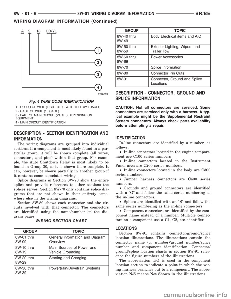
Fig. 4 WIRE CODE IDENTIFICATION
1 - COLOR OF WIRE (LIGHT BLUE WITH YELLOW TRACER
2 - GAGE OF WIRE (18 GAGE)
3 - PART OF MAIN CIRCUIT (VARIES DEPENDING ON
EQUIPMENT)
4 - MAIN CIRCUIT IDENTIFICATION
8W - 01 - 6 8W-01 WIRING DIAGRAM INFORMATIONBR/BE
WIRING DIAGRAM INFORMATION (Continued)
Page 676 of 2255
DIODE
REMOVAL
(1) Disconnect the battery.
(2) Locate the diode in the harness, and remove
the protective covering.
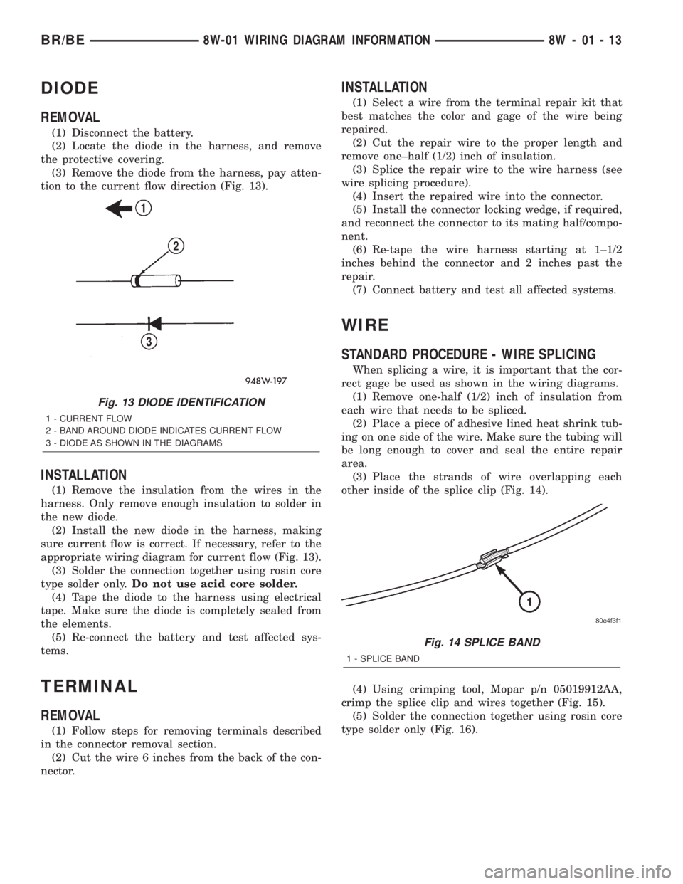
(3) Remove the diode from the harness, pay atten-
tion to the current flow direction (Fig. 13).
INSTALLATION
(1) Remove the insulation from the wires in the
harness. Only remove enough insulation to solder in
the new diode.
(2) Install the new diode in the harness, making
sure current flow is correct. If necessary, refer to the
appropriate wiring diagram for current flow (Fig. 13).
(3) Solder the connection together using rosin core
type solder only.Do not use acid core solder.
(4) Tape the diode to the harness using electrical
tape. Make sure the diode is completely sealed from
the elements.
(5) Re-connect the battery and test affected sys-
tems.
TERMINAL
REMOVAL
(1) Follow steps for removing terminals described
in the connector removal section.
(2) Cut the wire 6 inches from the back of the con-
nector.
INSTALLATION
(1) Select a wire from the terminal repair kit that
best matches the color and gage of the wire being
repaired.
(2) Cut the repair wire to the proper length and
remove one±half (1/2) inch of insulation.
(3) Splice the repair wire to the wire harness (see
wire splicing procedure).
(4) Insert the repaired wire into the connector.
(5) Install the connector locking wedge, if required,
and reconnect the connector to its mating half/compo-
nent.
(6) Re-tape the wire harness starting at 1±1/2
inches behind the connector and 2 inches past the
repair.
(7) Connect battery and test all affected systems.
WIRE
STANDARD PROCEDURE - WIRE SPLICING
When splicing a wire, it is important that the cor-
rect gage be used as shown in the wiring diagrams.
(1) Remove one-half (1/2) inch of insulation from
each wire that needs to be spliced.
(2) Place a piece of adhesive lined heat shrink tub-
ing on one side of the wire. Make sure the tubing will
be long enough to cover and seal the entire repair
area.
(3) Place the strands of wire overlapping each
other inside of the splice clip (Fig. 14).
(4) Using crimping tool, Mopar p/n 05019912AA,
crimp the splice clip and wires together (Fig. 15).
(5) Solder the connection together using rosin core
type solder only (Fig. 16).
Fig. 13 DIODE IDENTIFICATION
1 - CURRENT FLOW
2 - BAND AROUND DIODE INDICATES CURRENT FLOW
3 - DIODE AS SHOWN IN THE DIAGRAMS
Fig. 14 SPLICE BAND
1 - SPLICE BAND
BR/BE8W-01 WIRING DIAGRAM INFORMATION 8W - 01 - 13
Page 1018 of 2255
8W-91 CONNECTOR/GROUND/SPLICE LOCATION
TABLE OF CONTENTS
page
CONNECTOR/GROUND/SPLICE LOCATION
DESCRIPTION..........................1
CONNECTOR/GROUND/SPLICE
LOCATION
DESCRIPTION
This section provides illustrations identifying con-
nector, ground, and splice locations in the vehicle.Connector, ground, and splice indexes are provided.
Use the wiring diagrams in each section for connec-
tor, ground, and splice identification. Refer to the
index for the proper figure number. For items that
are not shown in this section N/S is placed in the
Fig. column.
CONNECTORS
CONNECTOR NAME/
NUMBERCOLOR LOCATION FIG.
4WD Switch BK On Front Axle N/S
A/C Compressor Clutch BK Rear of A/C Compressor 7, 8, 11
A/C Heater Control BK Center of Instrument Panel 33
A/C Heater Temperature
SelectNAT Center of Instrument Panel 33
A/C High Pressure Switch BK At A/C Compressor 7, 8, 11
A/C Low Pressure Switch BK Top of A/C Accumulator 1, 3
Accelerator Pedal Position
Sensor (Diesel)Left Front of Engine 13, 14
Aftermarket Trailer Tow
ConnectorRear of Vehicle N/S
Airbag Control Module Center of I.P. at Airbag Control Module 30
Ambient Temperature Sensor BK Radiator Left Support N/S
Ash Receiver Lamp BK Center of Instrument Panel 34
Back-up Lamp Switch (M/T) BK Top of Transmission 16
Battery Temperature Sensor BK Below Battery Tray 21
Blend Door Actuator Center of Instrument Panel N/S
Blower Motor BK Bottom Right of Instrument Panel 30
Blower Motor Resistor Block BK Bottom Right of Instrument Panel 34
Brake Lamp Switch Brake Pedal Arm 30, 32
Brake Pressure Switch BK At Master Cylinder 18
Bypass Jumper (A/T) GN Top Of Clutch Pedal 35
C105 Rear of Front Bumper N/S
C106 BK Rear of Front Bumper 22
C114 BK Radiator Left Support 20
C125 (Diesel) BK Left Rear of Engine Compartment 3
BR/BE8W-91 CONNECTOR/GROUND/SPLICE LOCATION 8W - 91 - 1
Page 1061 of 2255
tribution points for the electrical current required to
operate all of the many standard and optional facto-
ry-installed electrical and electronic powertrain,
chassis, safety, security, comfort and convenience sys-
tems. At the same time, the power distribution sys-
tem was designed to provide ready access to these
electrical distribution points for the vehicle techni-
cian to use when conducting diagnosis and repair of
faulty circuits. The power distribution system can
also prove useful for the sourcing of additional elec-
trical circuits that may be required to provide the
electrical current needed to operate many accessories
that the vehicle owner may choose to have installed
in the aftermarket.
SPECIAL TOOLS
POWER DISTRIBUTION SYSTEMS
CIGAR LIGHTER OUTLET
DESCRIPTION
A cigar lighter is standard equipment on this
model. The cigar lighter is installed in the instru-
ment panel next to the ash receiver, which is located
near the center of the instrument panel, below the
radio. The cigar lighter base is secured by a snap fit
within the instrument panel.
The cigar lighter knob and heating element unit,
and the cigar lighter receptacle unit are available for
service. These components cannot be repaired and, if
faulty or damaged, they must be replaced.
OPERATION
The cigar lighter consists of two major components:
a knob and heating element unit, and the cigar
lighter base or receptacle shell. The receptacle shell
is connected to ground, and an insulated contact in
the bottom of the shell is connected to battery cur-
rent. The cigar lighter receives battery voltage from afuse in the junction block only when the ignition
switch is in the Accessory or On positions.
The knob and heating element are encased within
a spring-loaded housing, which also features a sliding
protective heat shield. When the knob and heating
element are inserted in the receptacle shell, the heat-
ing element resistor coil is grounded through its
housing to the receptacle shell. If the cigar lighter
knob is pushed inward, the heat shield slides up
toward the knob exposing the heating element, and
the heating element extends from the housing toward
the insulated contact in the bottom of the receptacle
shell.
Two small spring-clip retainers are located on
either side of the insulated contact inside the bottom
of the receptacle shell. These clips engage and hold
the heating element against the insulated contact
long enough for the resistor coil to heat up. When the
heating element is engaged with the contact, battery
current can flow through the resistor coil to ground,
causing the resistor coil to heat.
When the resistor coil becomes sufficiently heated,
excess heat radiates from the heating element caus-
ing the spring-clips to expand. Once the spring-clips
expand far enough to release the heating element,
the spring-loaded housing forces the knob and heat-
ing element to pop back outward to their relaxed
position. When the cigar lighter knob and element
are pulled out of the receptacle shell, the protective
heat shield slides downward on the housing so that
the heating element is recessed and shielded around
its circumference for safety.
DIAGNOSIS AND TESTING - CIGAR LIGHTER
OUTLET
For complete circuit diagrams, refer toCigar
Lighterin Wiring Diagrams.
WARNING: REFER TO THE PASSIVE RESTRAINT
SECTION OF THE SERVICE MANUAL BEFORE
ATTEMPTING ANY STEERING WHEEL, STEERING
COLUMN, OR INSTRUMENT PANEL COMPONENT
DIAGNOSIS OR SERVICE. FAILURE TO TAKE THE
PROPER PRECAUTIONS COULD RESULT IN ACCI-
DENTAL AIRBAG DEPLOYMENT AND POSSIBLE
PERSONAL INJURY.
(1) Check the fused ignition switch output (run/ac-
cessory) fuse in the junction block. If OK, go to Step
2. If not OK, repair the shorted circuit or component
as required and replace the faulty fuse.
(2) Turn the ignition switch to the On position.
Check for battery voltage at the fused ignition switch
output (run/accessory) fuse in the junction block. If
OK, go to Step 3. If not OK, repair the open fused
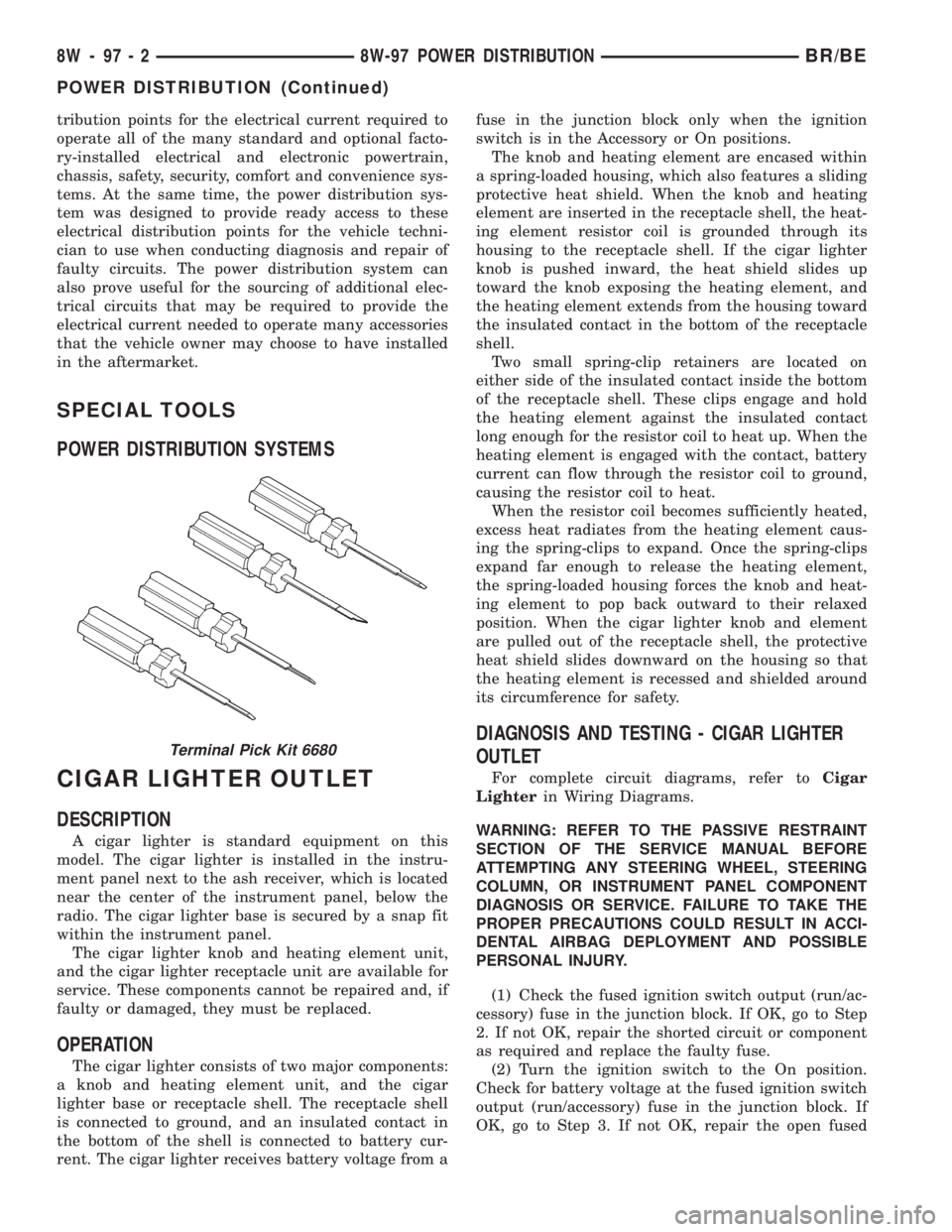
Terminal Pick Kit 6680
8W - 97 - 2 8W-97 POWER DISTRIBUTIONBR/BE
POWER DISTRIBUTION (Continued)
Page 1071 of 2255
(4) Press firmly on the cigar lighter or power out-
let receptacle base until the retaining bosses of the
mount are fully engaged in their receptacles.
(5) Install the cigar lighter knob and element into
the cigar lighter receptacle base, or the protective cap
into the power outlet receptacle base.
(6) Reconnect the battery negative cable.
HORN RELAY
DESCRIPTION
The horn relay is a International Standards Orga-
nization (ISO) micro-relay. The terminal designations
and functions are the same as a conventional ISO
relay. However, the micro-relay terminal orientation
(or footprint) is different, current capacity is lower,
and the relay case dimensions are smaller than those
of the conventional ISO relay.
The horn relay is a electromechanical device that
switches battery current to the horn when the horn
switch or when the high-line or premium Central
Timer Module (CTM) grounds the relay coil. See
Horn Relay in the Diagnosis and Testing section of
this group for more information.
The horn relay is located in the Power Distribution
Center (PDC), in the engine compartment. Refer to
the PDC label for relay identification and location.
If a problem is encountered with a continuously
sounding horn, it can usually be quickly resolved by
removing the horn relay from the PDC until further
diagnosis is completed.
The horn relay cannot be repaired and, if faulty or
damaged, it must be replaced.
DIAGNOSIS AND TESTING - HORN RELAY
The headlamp (or security) relay and the horn
relay are located in the Power Distribution Center
(PDC) in the engine compartment. Each of these
relays can be tested as described in the following pro-
cedure, however the circuits they are used in do vary.
To test the relay circuits, refer to the circuit descrip-
tions and diagrams in Wiring Diagrams.
WARNING: ON VEHICLES EQUIPPED WITH AIR-
BAGS, REFER TO THE RESTRAINTS SECTION OF
THE SERVICE MANUAL BEFORE ATTEMPTING ANY
STEERING WHEEL, STEERING COLUMN, OR
INSTRUMENT PANEL COMPONENT DIAGNOSIS OR
SERVICE. FAILURE TO TAKE THE PROPER PRE-
CAUTIONS COULD RESULT IN ACCIDENTAL AIR-
BAG DEPLOYMENT AND POSSIBLE PERSONAL
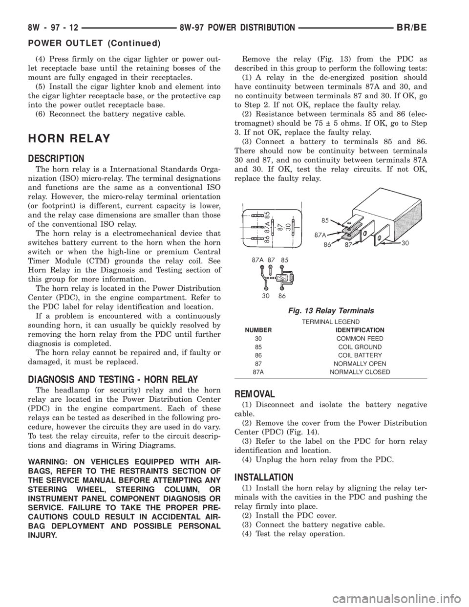
INJURY.Remove the relay (Fig. 13) from the PDC as
described in this group to perform the following tests:
(1) A relay in the de-energized position should
have continuity between terminals 87A and 30, and
no continuity between terminals 87 and 30. If OK, go
to Step 2. If not OK, replace the faulty relay.
(2) Resistance between terminals 85 and 86 (elec-
tromagnet) should be 75 5 ohms. If OK, go to Step
3. If not OK, replace the faulty relay.
(3) Connect a battery to terminals 85 and 86.
There should now be continuity between terminals
30 and 87, and no continuity between terminals 87A
and 30. If OK, test the relay circuits. If not OK,
replace the faulty relay.REMOVAL
(1) Disconnect and isolate the battery negative
cable.
(2) Remove the cover from the Power Distribution
Center (PDC) (Fig. 14).
(3) Refer to the label on the PDC for horn relay
identification and location.
(4) Unplug the horn relay from the PDC.
INSTALLATION
(1) Install the horn relay by aligning the relay ter-
minals with the cavities in the PDC and pushing the
relay firmly into place.
(2) Install the PDC cover.
(3) Connect the battery negative cable.
(4) Test the relay operation.
Fig. 13 Relay Terminals
TERMINAL LEGEND
NUMBER IDENTIFICATION
30 COMMON FEED
85 COIL GROUND
86 COIL BATTERY
87 NORMALLY OPEN
87A NORMALLY CLOSED
8W - 97 - 12 8W-97 POWER DISTRIBUTIONBR/BE
POWER OUTLET (Continued)
Page 1418 of 2255
(3) Remove the shipping lock pin if necessary.
(4) Install the column through the floor pan.
(5) Position the column bracket breakaway cap-
sules on the mounting studs. Install, butloose
assemblethe two upper bracket nuts.
(6) With the front wheels in the straight-ahead
position. Align steering column shaft to the coupler.
Install anewpinch bolt and tighten to 49 N´m (36
ft. lbs.).
(7) Clip the wiring harness on the steering column.
Connect the multi- function switch wiring and
tighten with 7mm socket.
(8) Install the upper fixed shroud.
(9) Be sure both breakaway capsules are fully
seated in the slots in the column support bracket.
Pull the column rearward then tighten upper bracket
nuts to 12 N´m (105 in. lbs.).
(10) Tighten the toe plate to floor pan attaching
nuts to 22.5 N´m (200 in. lbs.).
(11) Install the wiring connections to the column.
Install the lower fixed shroud.
(12) Column shift vehicles, install the PRNDL
driver cable. Place shifter in Park position. If indica-tor needs adjusting, turn thumb screw on cable
retainer to adjust cable.
(13) Install the lock housing shrouds. Install the
tilt lever (if equipped).
(14) Install the knee blocker and steering column
opening cover, (Refer to 23 - BODY/INSTRUMENT
PANEL/STEERING COLUMN OPENING COVER -
INSTALLATION).
(15) Install steering wheel and tighten nut to 61
N´m (45 ft. lbs.), (Refer to 19 - STEERING/COL-
UMN/STEERING WHEEL - INSTALLATION).
(16) Install the airbag, (Refer to 8 - ELECTRICAL/
RESTRAINTS/DRIVER AIRBAG - INSTALLATION).
(17) Column shift vehicles, connect the shift link
rod to the transmission shift lever. Use multi-purpose
lubricant, or an equivalent product, to aid the instal-
lation.
(18) Install the battery ground (negative) cable.
(19) Verify operation of the automatic transmission
shift linkage and adjust as necessary, (Refer to 21 -
TRANSMISSION/TRANSAXLE/AUTOMATIC -
44RE/GEAR SHIFT CABLE - ADJUSTMENTS).
SPECIFICATIONS
TORQUE CHART
TORQUE SPECIFICATIONS
DESCRIPTION N´m Ft. Lbs. In. Lbs.
Steering Wheel
Nut61 45 Ð
Steering Coupler
Bolt49 36 Ð
Steering Column
Upper Bracket12 Ð 105
Steering Column
Toe Plate23 Ð 200
KEY-IN IGNITION SWITCH
DESCRIPTION
The key-in ignition switch is integral to the igni-
tion switch, which is mounted on the left side of the
steering column. It closes a path to ground for the
Central Timer Module (CTM) when the ignition key
is inserted in the ignition lock cylinder and the
driver door ajar switch is closed (driver door is open).
The key-in ignition switch opens the ground path
when the key is removed from the ignition lock cyl-
inder. The ground path is also opened when the
driver door ajar switch is open (driver door is closed).The key-in ignition switch cannot be repaired and,
if faulty or damaged, the entire ignition switch must
be replaced, (Refer to 19 - STEERING/COLUMN/IG-
NITION SWITCH - REMOVAL).
DIAGNOSIS AND TESTING - IGNITION SWITCH
AND KEY LOCK CYLINDER
ELECTRICAL DIAGNOSIS
For ignition switch electrical schematics, refer to
Ignition Switch in the appropriate section of Electri-
cal Wiring Diagrams.
BR/BECOLUMN 19 - 9
COLUMN (Continued)