display DODGE RAM 2002 Service User Guide
[x] Cancel search | Manufacturer: DODGE, Model Year: 2002, Model line: RAM, Model: DODGE RAM 2002Pages: 2255, PDF Size: 62.07 MB
Page 404 of 2255
thirty-five milliamperes, isolate each circuit using the
fuse and circuit breaker remove-and-replace process
in Step 5. The multi-meter reading will drop to
within the acceptable limit when the source of the
excessive current draw is disconnected. Repair this
circuit as required; whether a wiring short, incorrect
switch adjustment, or a component failure is at fault.
STANDARD PROCEDURE - USING
MIDTRONICS ELECTRICAL TESTER
Always use the Midtronics Instruction Manual that
was supplied with the tester as a reference. If the
Instruction Manual is not available the following pro-
cedure can be used:
WARNING: ALWAYS WEAR APPROPRIATE EYE
PROTECTION AND USE EXTREME CAUTION WHEN
WORKING WITH BATTERIES.
BATTERY TESTING
(1) If testing the battery OUT-OF-VEHICLE, clean
the battery terminals with a wire brush before test-
ing. If the battery is equipped with side post termi-
nals, install and tighten the supplied lead terminal
stud adapters. Do not use steel bolts. Failure to prop-
erly install the stud adapters, or using stud adapters
that are dirty or worn-out may result in false test
readings.
(2) If testing the battery IN-THE-VEHICLE, make
certain all of the vehicle accessory loads are OFF,
including the ignition.The preferred test positionis at the battery terminal. If the battery is not
accessible, you may test using both the positive and
negative jumper posts. Select TESTING AT JUMPER
POST when connecting to that location.
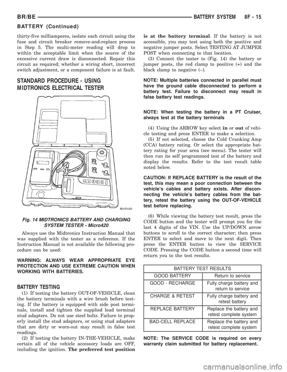
(3) Connect the tester to (Fig. 14) the battery or
jumper posts, the red clamp to positive (+) and the
black clamp to negative (±).
NOTE: Multiple batteries connected in parallel must
have the ground cable disconnected to perform a
battery test. Failure to disconnect may result in
false battery test readings.
NOTE: When testing the battery in a PT Cruiser,
always test at the battery terminals
(4) Using the ARROW key selectinoroutof vehi-
cle testing and press ENTER to make a selection.
(5) If not selected, choose the Cold Cranking Amp
(CCA) battery rating. Or select the appropriate bat-
tery rating for your area (see menu). The tester will
then run its self programmed test of the battery and
display the results. Refer to the test result table
noted below.
CAUTION: If REPLACE BATTERY is the result of the
test, this may mean a poor connection between the
vehicle's cables and battery exists. After discon-
necting the vehicle's battery cables from the bat-
tery, retest the battery using the OUT-OF-VEHICLE
test before replacing.
(6) While viewing the battery test result, press the
CODE button and the tester will prompt you for the
last 4 digits of the VIN. Use the UP/DOWN arrow
buttons to scroll to the correct character; then press
ENTER to select and move to the next digit. Then
press the ENTER button to view the SERVICE
CODE. Pressing the CODE button a second time will
return you to the test results.
BATTERY TEST RESULTS
GOOD BATTERY Return to service
GOOD - RECHARGE Fully charge battery and
return to service
CHARGE & RETEST Fully charge battery and
retest battery
REPLACE BATTERY Replace the battery and
retest complete system
BAD-CELL REPLACE Replace the battery and
retest complete system
NOTE: The SERVICE CODE is required on every
warranty claim submitted for battery replacement.
Fig. 14 MIDTRONICS BATTERY AND CHARGING
SYSTEM TESTER - Micro420
BR/BEBATTERY SYSTEM 8F - 15
BATTERY (Continued)
Page 432 of 2255
HEATED SYSTEMS
TABLE OF CONTENTS
page page
HEATED MIRRORS......................... 1 HEATED SEATSYSTEM..................... 5
HEATED MIRRORS
TABLE OF CONTENTS
page page
HEATED MIRRORS
DESCRIPTION - HEATED MIRROR SYSTEM . . . 1
OPERATION - HEATED MIRROR SYSTEM.....2
DIAGNOSIS AND TESTING - HEATED
MIRROR SYSTEM......................2
MIRROR SWITCH
DESCRIPTION..........................2
OPERATION............................3DIAGNOSIS AND TESTING - HEATED
MIRROR SWITCH......................3
HEATED MIRROR GRID
DESCRIPTION..........................4
OPERATION............................4
DIAGNOSIS AND TESTING - HEATED
MIRROR GRID.........................4
HEATED MIRRORS
DESCRIPTION - HEATED MIRROR SYSTEM
Electrically heated outside rear view mirrors are
an additional factory-installed option on models that
are equipped with factory-installed dual power mir-
rors. Vehicles with this option can be visually identi-
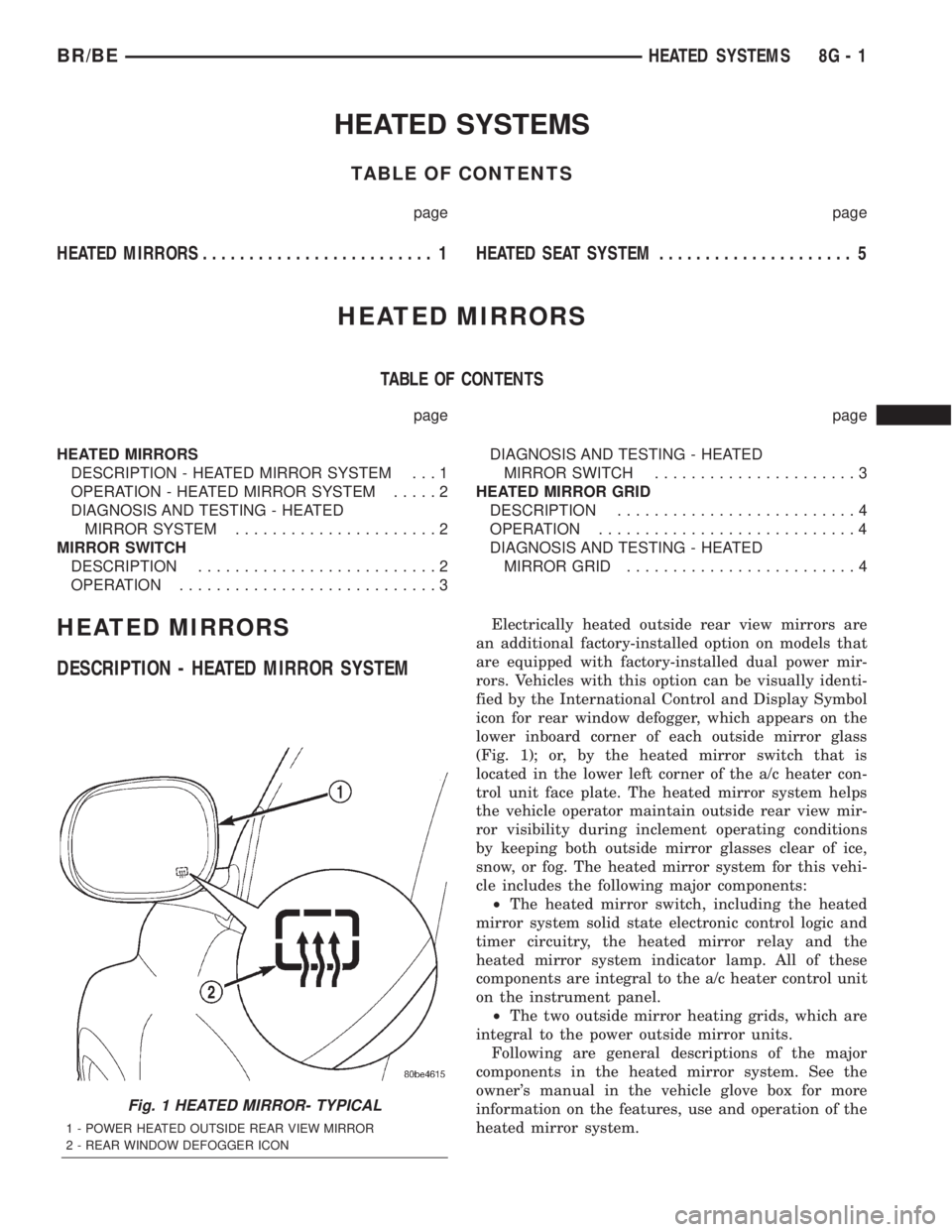
fied by the International Control and Display Symbol
icon for rear window defogger, which appears on the
lower inboard corner of each outside mirror glass
(Fig. 1); or, by the heated mirror switch that is
located in the lower left corner of the a/c heater con-
trol unit face plate. The heated mirror system helps
the vehicle operator maintain outside rear view mir-
ror visibility during inclement operating conditions
by keeping both outside mirror glasses clear of ice,
snow, or fog. The heated mirror system for this vehi-
cle includes the following major components:
²The heated mirror switch, including the heated
mirror system solid state electronic control logic and
timer circuitry, the heated mirror relay and the
heated mirror system indicator lamp. All of these
components are integral to the a/c heater control unit
on the instrument panel.
²The two outside mirror heating grids, which are
integral to the power outside mirror units.
Following are general descriptions of the major
components in the heated mirror system. See the
owner's manual in the vehicle glove box for more
information on the features, use and operation of the
heated mirror system.
Fig. 1 HEATED MIRROR- TYPICAL
1 - POWER HEATED OUTSIDE REAR VIEW MIRROR
2 - REAR WINDOW DEFOGGER ICON
BR/BEHEATED SYSTEMS 8G - 1
Page 470 of 2255
INSTALLATION
If engine has been cranked while distributor is
removed, establish the relationship between distribu-
tor shaft and number one piston position as follows:
Rotate crankshaft in a clockwise direction, as
viewed from front, until number one cylinder piston
is at top of compression stroke (compression should
be felt on finger with number one spark plug
removed). Then continue to slowly rotate engine
clockwise until indicating mark (Fig. 18) is aligned to
0 degree (TDC) mark on timing chain cover.
(1) Clean top of cylinder block for a good seal
between distributor base and block.
(2) Lightly oil the rubber o-ring seal on the distrib-
utor housing.
(3) Install rotor to distributor shaft.
(4) Position distributor into engine to its original
position. Engage tongue of distributor shaft with slot
in distributor oil pump drive gear. Position rotor to
the number one spark plug cable position.
(5) Install distributor holddown clamp and clamp
bolt. Do not tighten bolt at this time.
(6) Rotate the distributor housing until rotor is
aligned to CYL. NO. 1 alignment mark on the cam-
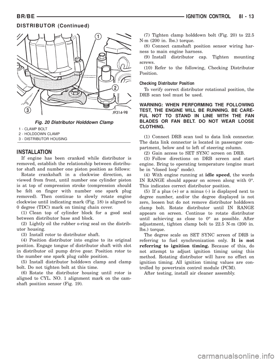
shaft position sensor (Fig. 19).(7) Tighten clamp holddown bolt (Fig. 20) to 22.5
N´m (200 in. lbs.) torque.
(8) Connect camshaft position sensor wiring har-
ness to main engine harness.
(9) Install distributor cap. Tighten mounting
screws.
(10) Refer to the following, Checking Distributor
Position.
Checking Distributor Position
To verify correct distributor rotational position, the
DRB scan tool must be used.
WARNING: WHEN PERFORMING THE FOLLOWING
TEST, THE ENGINE WILL BE RUNNING. BE CARE-
FUL NOT TO STAND IN LINE WITH THE FAN
BLADES OR FAN BELT. DO NOT WEAR LOOSE
CLOTHING.
(1) Connect DRB scan tool to data link connector.
The data link connector is located in passenger com-
partment, below and to left of steering column.
(2) Gain access to SET SYNC screen on DRB.
(3) Follow directions on DRB screen and start
engine. Bring to operating temperature (engine must
be in ªclosed loopº mode).
(4) With engine running atidle speed, the words
IN RANGE should appear on screen along with 0É.
This indicates correct distributor position.
(5) If a plus (+) or a minus (-) is displayed next to
degree number, and/or the degree displayed is not
zero, loosen but do not remove distributor holddown
clamp bolt. Rotate distributor until IN RANGE
appears on screen. Continue to rotate distributor
until achieving as close to 0É as possible. After
adjustment, tighten clamp bolt to 22.5 N´m (200 in.
lbs.) torque.
The degree scale on SET SYNC screen of DRB is
referring to fuel synchronization only.It is not
referring to ignition timing.Because of this, do
not attempt to adjust ignition timing using this
method. Rotating distributor will have no effect on
ignition timing. All ignition timing values are con-
trolled by powertrain control module (PCM).
After testing, install air cleaner assembly.
Fig. 20 Distributor Holddown Clamp
1 - CLAMP BOLT
2 - HOLDDOWN CLAMP
3 - DISTRIBUTOR HOUSING
BR/BEIGNITION CONTROL 8I - 13
DISTRIBUTOR (Continued)
Page 471 of 2255
DISTRIBUTOR CAP
DIAGNOSIS AND TESTING - DISTRIBUTOR
CAP
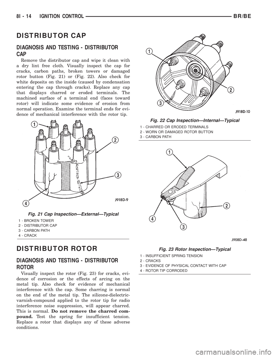
Remove the distributor cap and wipe it clean with
a dry lint free cloth. Visually inspect the cap for
cracks, carbon paths, broken towers or damaged
rotor button (Fig. 21) or (Fig. 22). Also check for
white deposits on the inside (caused by condensation
entering the cap through cracks). Replace any cap
that displays charred or eroded terminals. The
machined surface of a terminal end (faces toward
rotor) will indicate some evidence of erosion from
normal operation. Examine the terminal ends for evi-
dence of mechanical interference with the rotor tip.
DISTRIBUTOR ROTOR
DIAGNOSIS AND TESTING - DISTRIBUTOR
ROTOR
Visually inspect the rotor (Fig. 23) for cracks, evi-
dence of corrosion or the effects of arcing on the
metal tip. Also check for evidence of mechanical
interference with the cap. Some charring is normal
on the end of the metal tip. The silicone-dielectric-
varnish-compound applied to the rotor tip for radio
interference noise suppression, will appear charred.
This is normal.Do not remove the charred com-
pound.Test the spring for insufficient tension.
Replace a rotor that displays any of these adverse
conditions.
Fig. 21 Cap InspectionÐExternalÐTypical
1 - BROKEN TOWER
2 - DISTRIBUTOR CAP
3 - CARBON PATH
4 - CRACK
Fig. 22 Cap InspectionÐInternalÐTypical
1 - CHARRED OR ERODED TERMINALS
2 - WORN OR DAMAGED ROTOR BUTTON
3 - CARBON PATH
Fig. 23 Rotor InspectionÐTypical
1 - INSUFFICIENT SPRING TENSION
2 - CRACKS
3 - EVIDENCE OF PHYSICAL CONTACT WITH CAP
4 - ROTOR TIP CORRODED
8I - 14 IGNITION CONTROLBR/BE
Page 474 of 2255
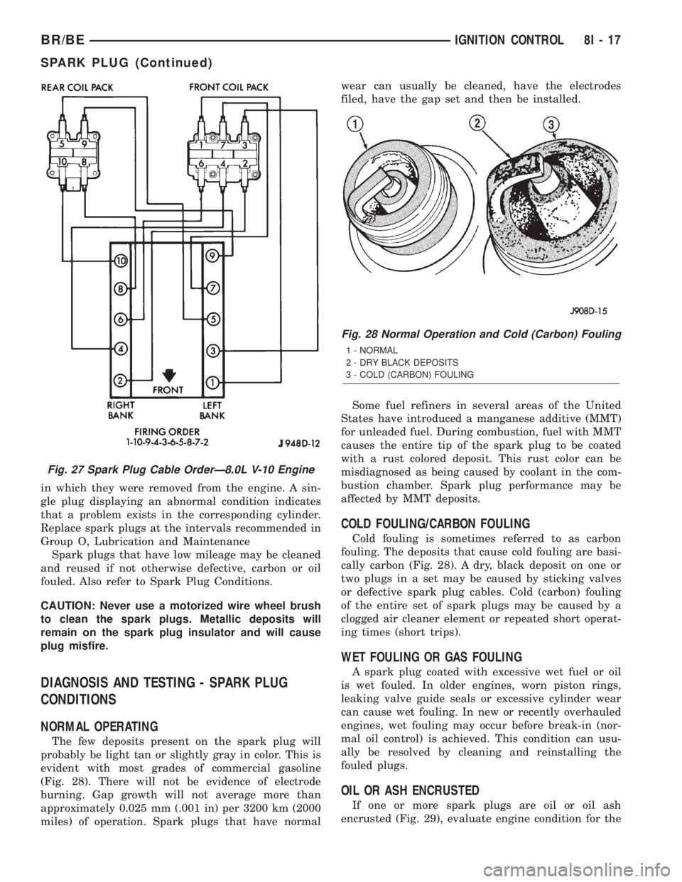
in which they were removed from the engine. A sin-
gle plug displaying an abnormal condition indicates
that a problem exists in the corresponding cylinder.
Replace spark plugs at the intervals recommended in
Group O, Lubrication and Maintenance
Spark plugs that have low mileage may be cleaned
and reused if not otherwise defective, carbon or oil
fouled. Also refer to Spark Plug Conditions.
CAUTION: Never use a motorized wire wheel brush
to clean the spark plugs. Metallic deposits will
remain on the spark plug insulator and will cause
plug misfire.
DIAGNOSIS AND TESTING - SPARK PLUG
CONDITIONS
NORMAL OPERATING
The few deposits present on the spark plug will
probably be light tan or slightly gray in color. This is
evident with most grades of commercial gasoline
(Fig. 28). There will not be evidence of electrode
burning. Gap growth will not average more than
approximately 0.025 mm (.001 in) per 3200 km (2000
miles) of operation. Spark plugs that have normalwear can usually be cleaned, have the electrodes
filed, have the gap set and then be installed.
Some fuel refiners in several areas of the United
States have introduced a manganese additive (MMT)
for unleaded fuel. During combustion, fuel with MMT
causes the entire tip of the spark plug to be coated
with a rust colored deposit. This rust color can be
misdiagnosed as being caused by coolant in the com-
bustion chamber. Spark plug performance may be
affected by MMT deposits.
COLD FOULING/CARBON FOULING
Cold fouling is sometimes referred to as carbon
fouling. The deposits that cause cold fouling are basi-
cally carbon (Fig. 28). A dry, black deposit on one or
two plugs in a set may be caused by sticking valves
or defective spark plug cables. Cold (carbon) fouling
of the entire set of spark plugs may be caused by a
clogged air cleaner element or repeated short operat-
ing times (short trips).
WET FOULING OR GAS FOULING
A spark plug coated with excessive wet fuel or oil
is wet fouled. In older engines, worn piston rings,
leaking valve guide seals or excessive cylinder wear
can cause wet fouling. In new or recently overhauled
engines, wet fouling may occur before break-in (nor-
mal oil control) is achieved. This condition can usu-
ally be resolved by cleaning and reinstalling the
fouled plugs.
OIL OR ASH ENCRUSTED
If one or more spark plugs are oil or oil ash
encrusted (Fig. 29), evaluate engine condition for the
Fig. 27 Spark Plug Cable OrderÐ8.0L V-10 Engine
Fig. 28 Normal Operation and Cold (Carbon) Fouling
1 - NORMAL
2 - DRY BLACK DEPOSITS
3 - COLD (CARBON) FOULING
BR/BEIGNITION CONTROL 8I - 17
SPARK PLUG (Continued)
Page 481 of 2255
INSTRUMENT CLUSTER
DESCRIPTION
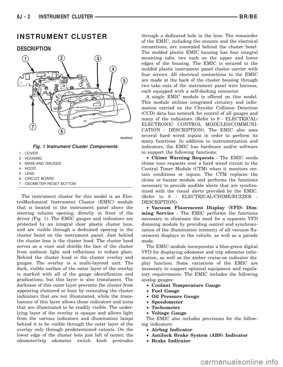
The instrument cluster for this model is an Elec-
troMechanical Instrument Cluster (EMIC) module
that is located in the instrument panel above the
steering column opening, directly in front of the
driver (Fig. 1). The EMIC gauges and indicators are
protected by an integral clear plastic cluster lens,
and are visible through a dedicated opening in the
cluster bezel on the instrument panel. Just behind
the cluster lens is the cluster hood. The cluster hood
serves as a visor and shields the face of the cluster
from ambient light and reflections to reduce glare.
Behind the cluster hood is the cluster overlay and
gauges. The overlay is a multi-layered unit. The
dark, visible surface of the outer layer of the overlay
is marked with all of the gauge identification and
graduations, but this layer is also translucent. The
darkness of this outer layer prevents the cluster from
appearing cluttered or busy by concealing the cluster
indicators that are not illuminated, while the trans-
lucence of this layer allows those indicators and icons
that are illuminated to be readily visible. The under-
lying layer of the overlay is opaque and allows light
from the various indicators and illumination lamps
behind it to be visible through the outer layer of the
overlay only through predetermined cutouts. On the
lower edge of the cluster lens just left of center, the
odometer/trip odometer switch knob protrudesthrough a dedicated hole in the lens. The remainder
of the EMIC, including the mounts and the electrical
connections, are concealed behind the cluster bezel.
The molded plastic EMIC housing has four integral
mounting tabs, two each on the upper and lower
edges of the housing. The EMIC is secured to the
molded plastic instrument panel cluster carrier with
four screws. All electrical connections to the EMIC
are made at the back of the cluster housing through
two take outs of the instrument panel wire harness,
each equipped with a self-docking connector.
A single EMIC module is offered on this model.
This module utilizes integrated circuitry and infor-
mation carried on the Chrysler Collision Detection
(CCD) data bus network for control of all gauges and
many of the indicators. (Refer to 8 - ELECTRICAL/
ELECTRONIC CONTROL MODULES/COMMUNI-
CATION - DESCRIPTION). The EMIC also uses
several hard wired inputs in order to perform its
many functions. In addition to instrumentation and
indicators, the EMIC has hardware and/or software
to support the following functions:
²Chime Warning Requests- The EMIC sends
chime tone requests over a hard wired circuit to the
Central Timer Module (CTM) when it monitors cer-
tain conditions or inputs. The CTM replaces the
chime or buzzer module and performs the functions
necessary to provide audible alerts that are synchro-
nized with the visual alerts provided by the EMIC.
(Refer to 8 - ELECTRICAL/CHIME/BUZZER -
DESCRIPTION).
²Vacuum Fluorescent Display (VFD) Dim-
ming Service- The EMIC performs the functions
necessary to eliminate the need for a separate VFD
dimming module by providing control and synchroni-
zation of the illumination intensity of all vacuum flu-
orescent displays in the vehicle, as well as a parade
mode.
The EMIC module incorporates a blue-green digital
VFD for displaying odometer and trip odometer infor-
mation, as well as the amber cruise-on indicator dis-
play function. Some variations of the EMIC are
necessary to support optional equipment and regula-
tory requirements. The EMIC includes the following
analog gauges:
²Coolant Temperature Gauge
²Fuel Gauge
²Oil Pressure Gauge
²Speedometer
²Tachometer
²Voltage Gauge
The EMIC also includes provisions for the follow-
ing indicators:
²Airbag Indicator
²Antilock Brake System (ABS) Indicator
²Brake Indicator
Fig. 1 Instrument Cluster Components
1 - COVER
2 - HOUSING
3 - MASK AND GAUGES
4 - HOOD
5 - LENS
6 - CIRCUIT BOARD
7 - ODOMETER RESET BUTTON
8J - 2 INSTRUMENT CLUSTERBR/BE
Page 483 of 2255
The EMIC circuitry operates on battery current
received through a fused B(+) fuse in the Junction
Block (JB) on a non-switched fused B(+) circuit, and
on battery current received through a fused ignition
switch output (st-run) fuse in the JB on a fused igni-
tion switch output (st-run) circuit. This arrangement
allows the EMIC to provide some features regardless
of the ignition switch position, while other features
will operate only with the ignition switch in the Start
or On positions. The EMIC circuitry is grounded
through two separate ground circuits located in one
of the two instrument cluster connectors and take
outs of the instrument panel wire harness. One
ground circuit receives ground through a take out
with an eyelet terminal connector of the instrument
panel wire harness that is secured by a nut to a
ground stud located on the left instrument panel end
bracket, while the other ground circuit receives
ground through a take out with an eyelet terminal
connector of the instrument panel wire harness that
is secured by a nut to a ground stud located on the
back of the instrument panel armature above the
inboard side of the instrument panel steering column
opening.
The EMIC also has a self-diagnostic actuator test
capability, which will test each of the CCD bus mes-
sage-controlled functions of the cluster by lighting
the appropriate indicators and positioning the gauge
needles at several predetermined locations on the
gauge faces in a prescribed sequence. (Refer to 8 -
ELECTRICAL/INSTRUMENT CLUSTER - DIAGNO-
SIS AND TESTING). See the owner's manual in the
vehicle glove box for more information on the fea-
tures, use and operation of the EMIC.
GAUGES
All gauges receive battery current through the
EMIC circuitry when the ignition switch is in the On
or Start positions. With the ignition switch in the Off
position battery current is not supplied to any
gauges, and the EMIC circuitry is programmed to
move all of the gauge needles back to the low end of
their respective scales. Therefore, the gauges do not
accurately indicate any vehicle condition unless the
ignition switch is in the On or Start positions. All of
the EMIC gauges, except the odometer, are air core
magnetic units. Two fixed electromagnetic coils are
located within each gauge. These coils are wrapped
at right angles to each other around a movable per-
manent magnet. The movable magnet is suspended
within the coils on one end of a pivot shaft, while the
gauge needle is attached to the other end of the
shaft. One of the coils has a fixed current flowing
through it to maintain a constant magnetic field
strength. Current flow through the second coil
changes, which causes changes in its magnetic fieldstrength. The current flowing through the second coil
is changed by the EMIC circuitry in response to mes-
sages received over the CCD data bus. The gauge
needle moves as the movable permanent magnet
aligns itself to the changing magnetic fields created
around it by the electromagnets.
The gauges are diagnosed using the EMIC self-di-
agnostic actuator test. (Refer to 8 - ELECTRICAL/
INSTRUMENT CLUSTER - DIAGNOSIS AND
TESTING). Proper testing of the CCD data bus and
the data bus message inputs to the EMIC that con-
trol each gauge require the use of a DRBIIItscan
tool. Refer to the appropriate diagnostic information.
Specific operation details for each gauge may be
found elsewhere in this service manual.
VACUUM-FLUORESCENT DISPLAY
The Vacuum-Fluorescent Display (VFD) module is
soldered to the EMIC circuit board. The display is
active with the ignition switch in the On or Start
positions, and inactive when the ignition switch is in
any other position. The VFD has several display
capabilities including odometer, trip odometer, and
an amber ªCRUISEº indication whenever the
optional speed control system is turned On. The
cruise indicator function of the VFD is automatically
enabled or disabled by the EMIC circuitry based
upon whether the vehicle is equipped with the speed
control option. An odometer/trip odometer switch on
the EMIC circuit board is used to control several of
the display modes. This switch is actuated manually
by depressing the odometer/trip odometer switch
knob that extends through the lower edge of the clus-
ter lens, just right of center. Actuating this switch
momentarily with the ignition switch in the On posi-
tion will toggle the VFD between the odometer and
trip odometer modes. The word ªTRIPº will also
appear in blue-green text when the VFD trip odome-
ter mode is active. Depressing the switch button for
about two seconds while the VFD is in the trip odom-
eter mode will reset the trip odometer value to zero.
Holding this switch depressed while turning the igni-
tion switch from the Off position to the On position
will activate the EMIC self-diagnostic actuator test.
The EMIC will automatically flash the odometer or
trip odometer information on and off if there is a loss
of CCD data bus communication. The VFD will also
display various information used in several diagnos-
tic procedures. Refer to the appropriate diagnostic
information for additional details on this VFD func-
tion.
The VFD is diagnosed using the EMIC self-diag-
nostic actuator test. (Refer to 8 - ELECTRICAL/IN-
STRUMENT CLUSTER - DIAGNOSIS AND
TESTING). Proper testing of the CCD data bus and
the data bus message inputs to the EMIC that con-
8J - 4 INSTRUMENT CLUSTERBR/BE
INSTRUMENT CLUSTER (Continued)
Page 484 of 2255
trol some of the VFD functions requires the use of a
DRBIIItscan tool. Refer to the appropriate diagnos-
tic information. Specific operation details for the
odometer and trip odometer functions of the VFD
may be found elsewhere in this service manual.
INDICATORS
Indicators are located in various positions within
the EMIC and are all connected to the EMIC circuit
board. The four-wheel drive indicator, high beam
indicator, washer fluid indicator, turn signal indica-
tors, and wait-to-start indicator are hard wired. The
brake indicator is controlled by CCD data bus mes-
sages from the Controller Anti-lock Brake (CAB) and
the hard wired park brake switch input to the EMIC.
The seatbelt indicator is controlled by the EMIC pro-
gramming, CCD data bus messages from the Airbag
Control Module (ACM), and the hard wired seat belt
switch input to the EMIC. The Malfunction Indicator
Lamp (MIL) is normally controlled by CCD data bus
messages from the Powertrain Control Module
(PCM); however, if the EMIC loses CCD data bus
communications, the EMIC circuitry will automati-
cally turn the MIL on, and flash the odometer VFD
on and off repeatedly until CCD data bus communi-
cation is restored. The EMIC uses CCD data bus
messages from the Powertrain Control Module
(PCM), the diesel engine only Engine Control Module
(ECM), the ACM, and the CAB to control all of the
remaining indicators. Different indicators are con-
trolled by different strategies; some receive fused
ignition switch output from the EMIC circuitry clus-
ter and have a switched ground, while others are
grounded through the EMIC circuitry and have a
switched battery feed.
In addition, certain indicators in this instrument
cluster are programmable or configurable. This fea-
ture allows the programmable indicators to be acti-
vated or deactivated with a DRBIIItscan tool, while
the configurable indicators will be automatically
enabled or disabled by the EMIC circuitry for com-
patibility with certain optional equipment. The only
programmable indicator for this model is the upshift
indicator. The cruise indicator, four-wheel drive indi-
cator, overdrive-off indicator, service reminder indica-
tor, and the transmission overtemp indicator are
automatically configured, either electronically or
mechanically.
The hard wired indicators are diagnosed using con-
ventional diagnostic methods. The EMIC and CCD
bus message controlled indicator lamps are diagnosed
using the EMIC self-diagnostic actuator test. (Refer
to 8 - ELECTRICAL/INSTRUMENT CLUSTER -
DIAGNOSIS AND TESTING). Proper testing of the
CCD data bus and the data bus message inputs to
the EMIC that control each indicator lamp requirethe use of a DRBIIItscan tool. Refer to the appro-
priate diagnostic information. Specific operation
details for each indicator may be found elsewhere in
this service manual.
CLUSTER ILLUMINATION
The EMIC has several illumination lamps that are
illuminated when the exterior lighting is turned on
with the headlamp switch. The illumination bright-
ness of these lamps is adjusted by the panel lamps
dimmer rheostat when the headlamp switch thumb-
wheel is rotated (down to dim, up to brighten). The
illumination lamps receive battery current through
the panel lamps dimmer rheostat and a fuse in the
JB on a fused panel lamps dimmer switch signal cir-
cuit. The illumination lamps are grounded at all
times.
In addition, an analog/digital (A/D) converter in
the EMIC converts the analog panel lamps dimmer
rheostat input from the headlamp switch to a digital
dimming level signal for controlling the lighting level
of the VFD. The EMIC also broadcasts this digital
dimming information as a message over the CCD
data bus for use by the Compass Mini-Trip Computer
(CMTC) in synchronizing the lighting level of its
VFD with that of the EMIC. The headlamp switch
thumbwheel also has a Parade position to provide a
parade mode. The EMIC monitors the request for
this mode through a hard wired day brightness sense
circuit input from the headlamp switch. In this mode,
the EMIC will override the selected panel dimmer
switch signal and send a message over the CCD data
bus to illuminate all vacuum fluorescent displays at
full brightness for easier visibility when driving in
daylight with the exterior lighting turned on. The
parade mode has no effect on the incandescent bulb
illumination intensity.
The hard wired cluster illumination lamps are
diagnosed using conventional diagnostic methods.
Proper testing of the VFD dimming level and the
CCD data bus dimming level message functions
requires the use of a DRBIIItscan tool. Refer to the
appropriate diagnostic information.
CHIME WARNING REQUESTS
The EMIC is programmed to request chime service
from the Central Timer Module (CTM) when certain
indicator lamps are illuminated. When the pro-
grammed conditions are met, the EMIC generates a
chime request signal and sends it over a hard wired
tone request circuit to the CTM. Upon receiving the
proper chime request, the CTM activates an integral
chime tone generator to provide the audible chime
tone to the vehicle operator. (Refer to 8 - ELECTRI-
CAL/CHIME/BUZZER - OPERATION). Proper test-
ing of the CTM and the EMIC chime requests
BR/BEINSTRUMENT CLUSTER 8J - 5
INSTRUMENT CLUSTER (Continued)
Page 485 of 2255
requires the use of a DRBIIItscan tool. Refer to the
appropriate diagnostic information.
DIAGNOSIS AND TESTING - INSTRUMENT
CLUSTER
If all of the instrument cluster gauges and/or indi-
cators are inoperative, refer to PRELIMINARY
DIAGNOSIS . If an individual gauge or Chrysler Col-
lision Detection (CCD) data bus message-controlled
indicator is inoperative, refer to ACTUATOR TEST .
If an individual hard wired indicator is inoperative,
refer to the diagnosis and testing information for
that specific indicator. If the instrument cluster
chime warning request function is inoperative, refer
to CHIME WARNING REQUEST DIAGNOSIS . If
the instrument cluster illumination lighting is inop-
erative, refer to CLUSTER ILLUMINATION DIAG-
NOSIS . If the instrument cluster Vacuum-
Fluorescent Display (VFD) dimmer service is
inoperative, use a DRBIIItscan tool to diagnose the
problem. Refer to the appropriate diagnostic proce-
dures. Refer to the appropriate wiring information.
The wiring information includes wiring diagrams,
proper wire and connector repair procedures, details
of wire harness routing and retention, connector pin-
out information and location views for the various
wire harness connectors, splices and grounds.
NOTE: Certain indicators in this instrument cluster
are programmable. This feature allows those indica-
tors to be activated or deactivated with a DRBIIIT
scan tool for compatibility with certain optional
equipment. If the problem being diagnosed involves
improper illumination of the upshift indicator, use a
DRBIIITscan tool to be certain that the instrument
cluster has been programmed with the proper vehi-
cle equipment option settings.
PRELIMINARY DIAGNOSIS
WARNING: ON VEHICLES EQUIPPED WITH AIR-
BAGS, DISABLE THE AIRBAG SYSTEM BEFORE
ATTEMPTING ANY STEERING WHEEL, STEERING
COLUMN, OR INSTRUMENT PANEL COMPONENT
DIAGNOSIS OR SERVICE. DISCONNECT AND ISO-
LATE THE BATTERY NEGATIVE (GROUND) CABLE,
THEN WAIT TWO MINUTES FOR THE AIRBAG SYS-
TEM CAPACITOR TO DISCHARGE BEFORE PER-
FORMING FURTHER DIAGNOSIS OR SERVICE. THIS
IS THE ONLY SURE WAY TO DISABLE THE AIRBAG
SYSTEM. FAILURE TO TAKE THE PROPER PRE-
CAUTIONS COULD RESULT IN ACCIDENTAL AIR-
BAG DEPLOYMENT AND POSSIBLE PERSONAL
INJURY.(1) If the indicators operate, but none of the
gauges operate, go to Step 2. If all of the gauges and
the CCD data bus message-controlled indicators are
inoperative, go to Step 5.
(2) Check the fused B(+) fuse (Fuse 14 - 10
ampere) in the Junction Block (JB). If OK, go to Step
3. If not OK, repair the shorted circuit or component
as required and replace the faulty fuse.
(3) Check for battery voltage at the fused B(+) fuse
(Fuse 14 - 10 ampere) in the JB. If OK, go to Step 4.
If not OK, repair the open fused B(+) circuit between
the JB and the Power Distribution Center (PDC) as
required.
(4) Disconnect and isolate the battery negative
cable. Remove the instrument cluster. Connect the
battery negative cable. Check for battery voltage at
the fused B(+) circuit cavity of the instrument panel
wire harness connector (Connector C1) for the instru-
ment cluster. If OK, refer to ACTUATOR TEST . If
not OK, repair the open fused B(+) circuit between
the instrument cluster and the JB as required.
(5) Check the fused ignition switch output (st-run)
fuse (Fuse 17 - 10 ampere) in the JB. If OK, go to
Step 6. If not OK, repair the shorted circuit or com-
ponent as required and replace the faulty fuse.
(6) Turn the ignition switch to the On position.
Check for battery voltage at the fused ignition switch
output (st-run) fuse (Fuse 17 - 10 ampere) in the JB.
If OK, go to Step 7. If not OK, repair the open fused
ignition switch output (st-run) circuit between the
instrument cluster and the JB as required.
(7) Turn the ignition switch to the Off position.
Disconnect and isolate the battery negative cable.
Reinstall the instrument cluster. Reconnect the bat-
tery negative cable. Turn the ignition switch to the
On position. Set the park brake. The brake indicator
in the instrument cluster should light. If OK, go to
Step 8. If not OK, go to Step 9.
(8) Turn the ignition switch to the Off position.
Turn on the park lamps and adjust the panel lamps
dimmer thumbwheel in the headlamp switch to the
full bright position. The cluster illumination lamps
should light. If OK, go to Step 10. If not OK, repair
the open ground circuit (Z3) between the instrument
cluster and ground (G201) as required.
(9) Turn the ignition switch to the Off position.
Disconnect and isolate the battery negative cable.
Remove the instrument cluster. Connect the battery
negative cable. Turn the ignition switch to the On
position. Check for battery voltage at the fused igni-
tion switch output (st-run) circuit cavity of the
instrument panel wire harness connector (Connector
C1). If OK, refer to ACTUATOR TEST . If not OK,
repair the open fused ignition switch output (st-run)
circuit between the instrument cluster and the JB as
required.
8J - 6 INSTRUMENT CLUSTERBR/BE
INSTRUMENT CLUSTER (Continued)
Page 486 of 2255
(10) Disconnect and isolate the battery negative
cable. Remove the instrument cluster. Check for con-
tinuity between the ground circuit (Z2) cavity of the
instrument panel wire harness connector (Connector
C1) and a good ground. There should be continuity. If
OK, refer to ACTUATOR TEST . If not OK, repair
the open ground circuit to ground (G200) as required.
ACTUATOR TEST
WARNING: ON VEHICLES EQUIPPED WITH AIR-
BAGS, DISABLE THE AIRBAG SYSTEM BEFORE
ATTEMPTING ANY STEERING WHEEL, STEERING
COLUMN, OR INSTRUMENT PANEL COMPONENT
DIAGNOSIS OR SERVICE. DISCONNECT AND ISO-
LATE THE BATTERY NEGATIVE (GROUND) CABLE,
THEN WAIT TWO MINUTES FOR THE AIRBAG SYS-
TEM CAPACITOR TO DISCHARGE BEFORE PER-
FORMING FURTHER DIAGNOSIS OR SERVICE. THIS
IS THE ONLY SURE WAY TO DISABLE THE AIRBAG
SYSTEM. FAILURE TO TAKE THE PROPER PRE-
CAUTIONS COULD RESULT IN ACCIDENTAL AIR-
BAG DEPLOYMENT AND POSSIBLE PERSONAL
INJURY.
The instrument cluster actuator test will put the
instrument cluster into its self-diagnostic mode. In
this mode the instrument cluster can perform a self-
diagnostic test that will confirm that the instrument
cluster circuitry, the gauges, and the CCD data bus
message-controlled indicators are capable of operat-
ing as designed. During the actuator test the instru-
ment cluster circuitry position each of the gaugeneedles at various calibration points, illuminate each
of the segments in the Vacuum-Fluorescent Display
(VFD), and turn all of the CCD data bus message-
controlled indicators on and off.
Successful completion of the actuator test will con-
firm that the instrument cluster is operational. How-
ever, there may still be a problem with the CCD data
bus, the Powertrain Control Module (PCM), the
Engine Control Module (ECM), the Airbag Control
Module (ACM), the Controller Anti-lock Brake (CAB),
or the inputs to one of these electronic control mod-
ules. Use a DRBIIItscan tool to diagnose these com-
ponents. Refer to the appropriate diagnostic
information.
(1) Begin the test with the ignition switch in the
Off position.
(2) Depress the odometer/trip odometer switch but-
ton.
(3) While still holding the odometer/trip odometer
switch button depressed, turn the ignition switch to
the On position, but do not start the engine.
(4) Keep the odometer/trip odometer switch button
depressed for about ten seconds, untilCHEC
appears in the odometer display, then release the
odometer/trip odometer switch button.
(5) A series of three-digit numeric failure messages
may appear in the odometer display, depending upon
the failure mode. If a failure message appears, refer
to the Instrument Cluster Failure Message chart for
the description and proper correction. If no failure
message appears, the actuator test will proceed as
described in Step 6.
INSTRUMENT CLUSTER FAILURE MESSAGE
Message Description Correction
110 A failure has been identified in the cluster
CPU, RAM, or EEPROM.1. Replace the faulty cluster.
900 The CCD data bus is not operational. 1. Check the CCD data bus connections at the
cluster.
2. Check the cluster fuses.
3. Check the CCD data bus bias.
4. Check the CCD data bus voltage.
5. Check the CCD data bus terminations.
920 The cluster is not receiving a vehicle speed
message from the PCM.1. Check the PCM software level and reflash if
required.
2. Use a DRBIIITscan tool to verify that the
vehicle speed message is being sent by the
PCM.
921 The cluster is not receiving a distance pulse
message from the PCM.1. Check the PCM software level and reflash if
required.
2. Use a DRBIIITscan tool to verify that the
distance pulse message is being sent by the
PCM.
BR/BEINSTRUMENT CLUSTER 8J - 7
INSTRUMENT CLUSTER (Continued)