transmission fluid DODGE RAM 2002 Service User Guide
[x] Cancel search | Manufacturer: DODGE, Model Year: 2002, Model line: RAM, Model: DODGE RAM 2002Pages: 2255, PDF Size: 62.07 MB
Page 233 of 2255
OPERATION
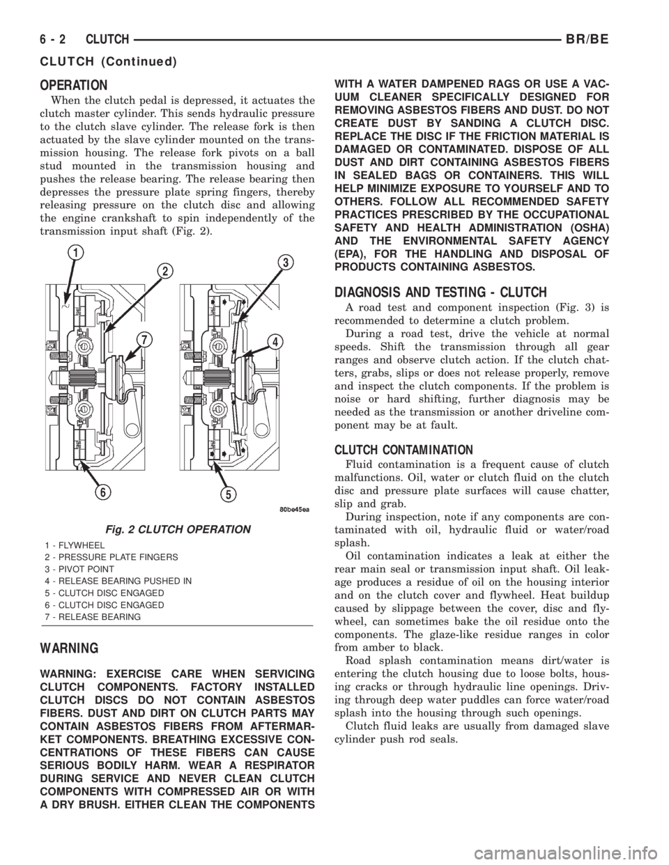
When the clutch pedal is depressed, it actuates the
clutch master cylinder. This sends hydraulic pressure
to the clutch slave cylinder. The release fork is then
actuated by the slave cylinder mounted on the trans-
mission housing. The release fork pivots on a ball
stud mounted in the transmission housing and
pushes the release bearing. The release bearing then
depresses the pressure plate spring fingers, thereby
releasing pressure on the clutch disc and allowing
the engine crankshaft to spin independently of the
transmission input shaft (Fig. 2).
WARNING
WARNING: EXERCISE CARE WHEN SERVICING
CLUTCH COMPONENTS. FACTORY INSTALLED
CLUTCH DISCS DO NOT CONTAIN ASBESTOS
FIBERS. DUST AND DIRT ON CLUTCH PARTS MAY
CONTAIN ASBESTOS FIBERS FROM AFTERMAR-
KET COMPONENTS. BREATHING EXCESSIVE CON-
CENTRATIONS OF THESE FIBERS CAN CAUSE
SERIOUS BODILY HARM. WEAR A RESPIRATOR
DURING SERVICE AND NEVER CLEAN CLUTCH
COMPONENTS WITH COMPRESSED AIR OR WITH
A DRY BRUSH. EITHER CLEAN THE COMPONENTSWITH A WATER DAMPENED RAGS OR USE A VAC-
UUM CLEANER SPECIFICALLY DESIGNED FOR
REMOVING ASBESTOS FIBERS AND DUST. DO NOT
CREATE DUST BY SANDING A CLUTCH DISC.
REPLACE THE DISC IF THE FRICTION MATERIAL IS
DAMAGED OR CONTAMINATED. DISPOSE OF ALL
DUST AND DIRT CONTAINING ASBESTOS FIBERS
IN SEALED BAGS OR CONTAINERS. THIS WILL
HELP MINIMIZE EXPOSURE TO YOURSELF AND TO
OTHERS. FOLLOW ALL RECOMMENDED SAFETY
PRACTICES PRESCRIBED BY THE OCCUPATIONAL
SAFETY AND HEALTH ADMINISTRATION (OSHA)
AND THE ENVIRONMENTAL SAFETY AGENCY
(EPA), FOR THE HANDLING AND DISPOSAL OF
PRODUCTS CONTAINING ASBESTOS.
DIAGNOSIS AND TESTING - CLUTCH
A road test and component inspection (Fig. 3) is
recommended to determine a clutch problem.
During a road test, drive the vehicle at normal
speeds. Shift the transmission through all gear
ranges and observe clutch action. If the clutch chat-
ters, grabs, slips or does not release properly, remove
and inspect the clutch components. If the problem is
noise or hard shifting, further diagnosis may be
needed as the transmission or another driveline com-
ponent may be at fault.
CLUTCH CONTAMINATION
Fluid contamination is a frequent cause of clutch
malfunctions. Oil, water or clutch fluid on the clutch
disc and pressure plate surfaces will cause chatter,
slip and grab.
During inspection, note if any components are con-
taminated with oil, hydraulic fluid or water/road
splash.
Oil contamination indicates a leak at either the
rear main seal or transmission input shaft. Oil leak-
age produces a residue of oil on the housing interior
and on the clutch cover and flywheel. Heat buildup
caused by slippage between the cover, disc and fly-
wheel, can sometimes bake the oil residue onto the
components. The glaze-like residue ranges in color
from amber to black.
Road splash contamination means dirt/water is
entering the clutch housing due to loose bolts, hous-
ing cracks or through hydraulic line openings. Driv-
ing through deep water puddles can force water/road
splash into the housing through such openings.
Clutch fluid leaks are usually from damaged slave
cylinder push rod seals.
Fig. 2 CLUTCH OPERATION
1 - FLYWHEEL
2 - PRESSURE PLATE FINGERS
3 - PIVOT POINT
4 - RELEASE BEARING PUSHED IN
5 - CLUTCH DISC ENGAGED
6 - CLUTCH DISC ENGAGED
7 - RELEASE BEARING
6 - 2 CLUTCHBR/BE
CLUTCH (Continued)
Page 235 of 2255
IMPROPER RELEASE OR CLUTCH ENGAGEMENT
Clutch release or engagement problems are caused
by wear or damage to one or more clutch compo-
nents. A visual inspection of the release components
will usually reveal the problem part.
Release problems can result in hard shifting and
noise. Items to look for are: leaks at the clutch cylin-
ders and interconnecting line; loose slave cylinder
bolts; worn/loose release fork and pivot stud; dam-
aged release bearing; and a worn clutch disc, or pres-
sure plate.
Normal condensation in vehicles that are stored or
out of service for long periods of time can generate
enough corrosion to make the disc stick to the fly-
wheel, or pressure plate. If this condition is experi-
enced, correction only requires that the disc be
loosened manually through the inspection plate open-
ing.
Engagement problems usually result in slip, chat-
ter/shudder, and noisy operation. The primary causes
are clutch disc contamination; clutch disc wear; mis-
alignment, or distortion; flywheel damage; or a com-
bination of the foregoing. A visual inspection is
required to determine the part actually causing the
problem.
CLUTCH MISALIGNMENT
Clutch components must be in proper alignment
with the crankshaft and transmission input shaft.
Misalignment caused by excessive runout or warpage
of any clutch component will cause grab, chatter and
improper clutch release.
CLUTCH COVER AND DISC RUNOUT
Check the clutch disc before installation. Axial
(face) runout of anewdisc should not exceed 0.50
mm (0.020 in.). Measure runout about 6 mm (1/4 in.)
from the outer edge of the disc facing. Obtain
another disc if runout is excessive.
Check condition of the clutch before installation. A
warped cover or diaphragm spring will cause grab
and incomplete release or engagement. Be careful
when handling the cover and disc. Impact can distort
the cover, diaphragm spring, release fingers and the
hub of the clutch disc.
Use an alignment tool when positioning the disc on
the flywheel. The tool prevents accidental misalign-
ment which could result in cover distortion and disc
damage.
A frequent cause of clutch cover distortion (and
consequent misalignment) is improper bolt tighten-
ing.
DIAGNOSIS CHART
The clutch inspection chart (Fig. 3) outlines items
to be checked before and during clutch installation.
Use the chart as a check list to help avoid overlook-
ing potential problem sources during service opera-
tions.
The diagnosis charts Diagnosis Chart describe
common clutch problems, causes and correction.
Fault conditions are listed at the top of each chart.
Conditions, causes and corrective action are outlined
in the indicated columns.
The charts are provided as a convenient reference
when diagnosing faulty clutch operation.
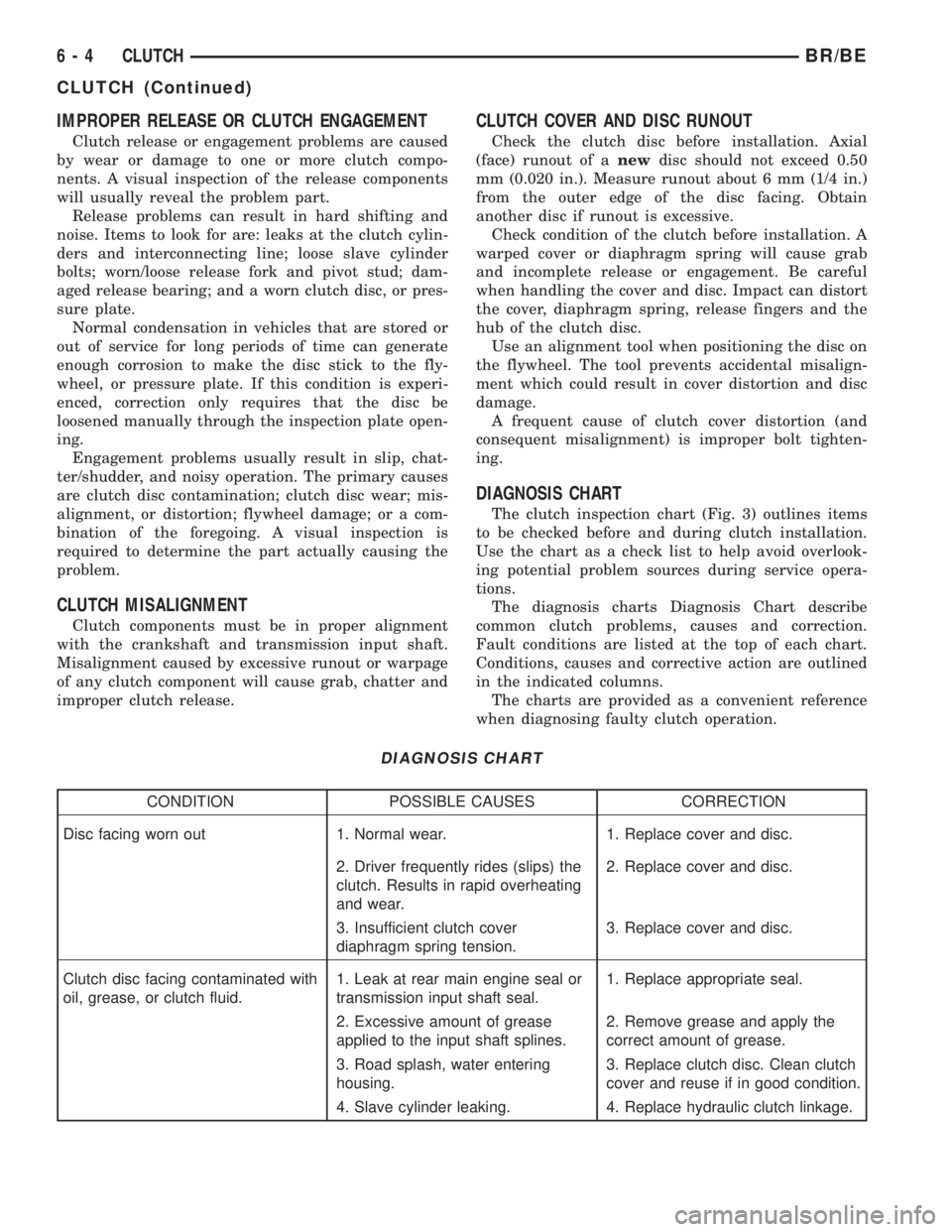
DIAGNOSIS CHART
CONDITION POSSIBLE CAUSES CORRECTION
Disc facing worn out 1. Normal wear. 1. Replace cover and disc.
2. Driver frequently rides (slips) the
clutch. Results in rapid overheating
and wear.2. Replace cover and disc.
3. Insufficient clutch cover
diaphragm spring tension.3. Replace cover and disc.
Clutch disc facing contaminated with
oil, grease, or clutch fluid.1. Leak at rear main engine seal or
transmission input shaft seal.1. Replace appropriate seal.
2. Excessive amount of grease
applied to the input shaft splines.2. Remove grease and apply the
correct amount of grease.
3. Road splash, water entering
housing.3. Replace clutch disc. Clean clutch
cover and reuse if in good condition.
4. Slave cylinder leaking. 4. Replace hydraulic clutch linkage.
6 - 4 CLUTCHBR/BE
CLUTCH (Continued)
Page 238 of 2255
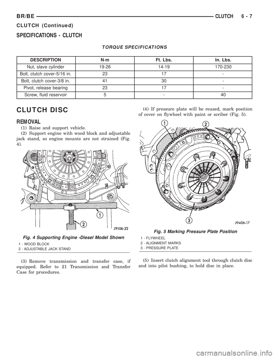
SPECIFICATIONS - CLUTCH
TORQUE SPECIFICATIONS
DESCRIPTION N´m Ft. Lbs. In. Lbs.
Nut, slave cylinder 19-26 14-19 170-230
Bolt, clutch cover-5/16 in. 23 17 -
Bolt, clutch cover-3/8 in. 41 30 -
Pivot, release bearing 23 17 -
Screw, fluid reservoir 5 - 40
CLUTCH DISC
REMOVAL
(1) Raise and support vehicle.
(2) Support engine with wood block and adjustable
jack stand, so engine mounts are not strained (Fig.
4).
(3) Remove transmission and transfer case, if
equipped. Refer to 21 Transmission and Transfer
Case for procedures.(4) If pressure plate will be reused, mark position
of cover on flywheel with paint or scriber (Fig. 5).
(5) Insert clutch alignment tool through clutch disc
and into pilot bushing, to hold disc in place.
Fig. 4 Supporting Engine -Diesel Model Shown
1 - WOOD BLOCK
2 - ADJUSTABLE JACK STAND
Fig. 5 Marking Pressure Plate Position
1 - FLYWHEEL
2 - ALIGNMENT MARKS
3 - PRESSURE PLATE
BR/BECLUTCH 6 - 7
CLUTCH (Continued)
Page 239 of 2255
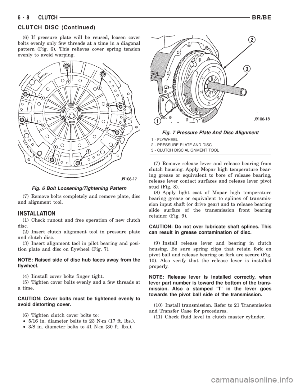
(6) If pressure plate will be reused, loosen cover
bolts evenly only few threads at a time in a diagonal
pattern (Fig. 6). This relieves cover spring tension
evenly to avoid warping.
(7) Remove bolts completely and remove plate, disc
and alignment tool.
INSTALLATION
(1) Check runout and free operation of new clutch
disc.
(2) Insert clutch alignment tool in pressure plate
and clutch disc.
(3) Insert alignment tool in pilot bearing and posi-
tion plate and disc on flywheel (Fig. 7).
NOTE: Raised side of disc hub faces away from the
flywheel.
(4) Iinstall cover bolts finger tight.
(5) Tighten cover bolts evenly and a few threads at
a time.
CAUTION: Cover bolts must be tightened evenly to
avoid distorting cover.
(6) Tighten clutch cover bolts to:
²5/16 in. diameter bolts to 23 N´m (17 ft. lbs.).
²3/8 in. diameter bolts to 41 N´m (30 ft. lbs.).(7) Remove release lever and release bearing from
clutch housing. Apply Mopar high temperature bear-
ing grease or equivalent to bore of release bearing,
release lever contact surfaces and release lever pivot
stud (Fig. 8).
(8) Apply light coat of Mopar high temperature
bearing grease or equivalent to splines of transmis-
sion input shaft (or drive gear) and to release bearing
slide surface of the transmission front bearing
retainer (Fig. 9).
CAUTION: Do not over lubricate shaft splines. This
can result in grease contamination of disc.
(9) Install release lever and bearing in clutch
housing. Be sure spring clips that retain fork on
pivot ball and release bearing on fork are secure (Fig.
10). Also verify that the release lever is installed
properly.
NOTE: Release lever is installed correctly, when
lever part number is toward the bottom of the trans-
mission. Also a stamped ªIº in the lever goes
towards the pivot ball side of the transmission.
(10) Install transmission. Refer to 21 Transmission
and Transfer Case for procedures.
(11) Check fluid level in clutch master cylinder.
Fig. 6 Bolt Loosening/Tightening Pattern
Fig. 7 Pressure Plate And Disc Alignment
1 - FLYWHEEL
2 - PRESSURE PLATE AND DISC
3 - CLUTCH DISC ALIGNMENT TOOL
6 - 8 CLUTCHBR/BE
CLUTCH DISC (Continued)
Page 250 of 2255
COOLING
TABLE OF CONTENTS
page page
COOLING
DESCRIPTION
DESCRIPTION - COOLING SYSTEM FLOW -
5.9L ENGINE..........................1
DESCRIPTIONÐCOOLING SYSTEM FLOW -
5.9L DIESEL..........................2
DESCRIPTIONÐHOSE CLAMPS...........4
OPERATION
OPERATIONÐHOSE CLAMPS............4
OPERATIONÐCOOLING SYSTEM.........4
DIAGNOSIS AND TESTING
DIAGNOSIS AND TESTING - PRELIMINARY
CHECKS.............................4
DIAGNOSIS AND TESTINGÐON-BOARD
DIAGNOSTICS (OBD)...................5
DIAGNOSIS AND TESTING - COOLING
SYSTEM LEAKS.......................5
DIAGNOSIS AND TESTING - COOLING
SYSTEM GAS ENGINE..................7
DIAGNOSIS AND TESTING - COOLING
SYSTEM DIESEL ENGINE...............13
STANDARD PROCEDURE
STANDARD PROCEDURE - DRAINING
COOLING SYSTEM 5.9L/8.0L ENGINES....15STANDARD PROCEDUREÐDRAINING
COOLING SYSTEM 5.9L DIESEL ENGINE . . . 15
STANDARD PROCEDURE - REFILLING
COOLING SYSTEM 5.9L/8.0L ENGINES....16
STANDARD PROCEDUREÐREFILLING
COOLING SYSTEM 5.9L DIESEL ENGINE . . . 16
STANDARD PROCEDURE - ADDING
ADDITIONAL COOLANT.................16
STANDARD PROCEDUREÐCOOLANT
LEVEL CHECK........................16
STANDARD PROCEDURE - COOLING
SYSTEM CLEANING/REVERSE FLUSHING . . 17
STANDARD PROCEDURE - COOLANT
SELECTION - ADDITIVES...............17
SPECIFICATIONS
TORQUE............................18
SPECIAL TOOLS
COOLING...........................18
ACCESSORY DRIVE......................19
ENGINE...............................38
TRANSMISSION.........................78
COOLING
DESCRIPTION
DESCRIPTION - COOLING SYSTEM FLOW -
5.9L ENGINE
The cooling system regulates engine operating tem-
perature. It allows the engine to reach normal oper-
ating temperature as quickly as possible. It also
maintains normal operating temperature and pre-
vents overheating.The cooling system also provides a means of heat-
ing the passenger compartment and cooling the auto-
matic transmission fluid (if equipped). The cooling
system is pressurized and uses a centrifugal water
pump to circulate coolant throughout the system.
An optional factory installed maximum duty cool-
ing package is available on most models. This pack-
age will provide additional cooling capacity for
vehicles used under extreme conditions such as
trailer towing in high ambient temperatures (Fig. 1).
BR/BECOOLING 7 - 1
Page 253 of 2255
DESCRIPTIONÐHOSE CLAMPS
The cooling system utilizes both worm drive and
spring type hose clamps. If a spring type clamp
replacement is necessary, replace with the original
Mopartequipment spring type clamp.
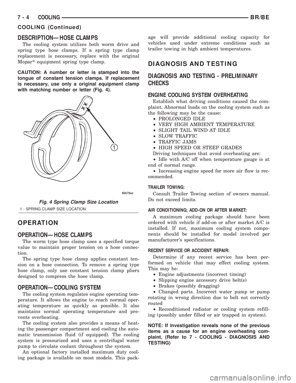
CAUTION: A number or letter is stamped into the
tongue of constant tension clamps. If replacement
is necessary, use only a original equipment clamp
with matching number or letter (Fig. 4).
OPERATION
OPERATIONÐHOSE CLAMPS
The worm type hose clamp uses a specified torque
value to maintain proper tension on a hose connec-
tion.
The spring type hose clamp applies constant ten-
sion on a hose connection. To remove a spring type
hose clamp, only use constant tension clamp pliers
designed to compress the hose clamp.
OPERATIONÐCOOLING SYSTEM
The cooling system regulates engine operating tem-
perature. It allows the engine to reach normal oper-
ating temperature as quickly as possible. It also
maintains normal operating temperature and pre-
vents overheating.
The cooling system also provides a means of heat-
ing the passenger compartment and cooling the auto-
matic transmission fluid (if equipped). The cooling
system is pressurized and uses a centrifugal water
pump to circulate coolant throughout the system.
An optional factory installed maximum duty cool-
ing package is available on most models. This pack-age will provide additional cooling capacity for
vehicles used under extreme conditions such as
trailer towing in high ambient temperatures.
DIAGNOSIS AND TESTING
DIAGNOSIS AND TESTING - PRELIMINARY
CHECKS
ENGINE COOLING SYSTEM OVERHEATING
Establish what driving conditions caused the com-
plaint. Abnormal loads on the cooling system such as
the following may be the cause:
²PROLONGED IDLE
²VERY HIGH AMBIENT TEMPERATURE
²SLIGHT TAIL WIND AT IDLE
²SLOW TRAFFIC
²TRAFFIC JAMS
²HIGH SPEED OR STEEP GRADES
Driving techniques that avoid overheating are:
²Idle with A/C off when temperature gauge is at
end of normal range.
²Increasing engine speed for more air flow is rec-
ommended.
TRAILER TOWING:
Consult Trailer Towing section of owners manual.
Do not exceed limits.
AIR CONDITIONING; ADD-ON OR AFTER MARKET:
A maximum cooling package should have been
ordered with vehicle if add-on or after market A/C is
installed. If not, maximum cooling system compo-
nents should be installed for model involved per
manufacturer's specifications.
RECENT SERVICE OR ACCIDENT REPAIR:
Determine if any recent service has been per-
formed on vehicle that may effect cooling system.
This may be:
²Engine adjustments (incorrect timing)
²Slipping engine accessory drive belt(s)
²Brakes (possibly dragging)
²Changed parts. Incorrect water pump or pump
rotating in wrong direction due to belt not correctly
routed
²Reconditioned radiator or cooling system refill-
ing (possibly under filled or air trapped in system).
NOTE: If investigation reveals none of the previous
items as a cause for an engine overheating com-
plaint, (Refer to 7 - COOLING - DIAGNOSIS AND
TESTING)
Fig. 4 Spring Clamp Size Location
1 - SPRING CLAMP SIZE LOCATION
7 - 4 COOLINGBR/BE
COOLING (Continued)
Page 255 of 2255
hoses, gasket edges and heater. Seal small leak holes
with a Sealer Lubricant (or equivalent). Repair leak
holes and inspect system again with pressure
applied.
Drops Quickly:Indicates that serious leakage is
occurring. Examine system for external leakage. If
leaks are not visible, inspect for internal leakage.
Large radiator leak holes should be repaired by a
reputable radiator repair shop.
INTERNAL LEAKAGE INSPECTION
Remove engine oil pan drain plug and drain a
small amount of engine oil. If coolant is present in
the pan, it will drain first because it is heavier than
oil. An alternative method is to operate engine for a
short period to churn the oil. After this is done,
remove engine dipstick and inspect for water glob-
ules. Also inspect transmission dipstick for water
globules and transmission fluid cooler for leakage.
WARNING: WITH RADIATOR PRESSURE TESTER
TOOL INSTALLED ON RADIATOR, DO NOT ALLOW
PRESSURE TO EXCEED 110 KPA (20 PSI). PRES-
SURE WILL BUILD UP QUICKLY IF A COMBUSTION
LEAK IS PRESENT. TO RELEASE PRESSURE,
ROCK TESTER FROM SIDE TO SIDE. WHEN
REMOVING TESTER, DO NOT TURN TESTER MORE
THAN 1/2 TURN IF SYSTEM IS UNDER PRESSURE.
Operate engine without pressure cap on radiator
until thermostat opens. Attach a Pressure Tester to
filler neck. If pressure builds up quickly it indicates acombustion leak exists. This is usually the result of a
cylinder head gasket leak or crack in engine. Repair
as necessary.
If there is not an immediate pressure increase,
pump the Pressure Tester. Do this until indicated
pressure is within system range of 110 kPa (16 psi).
Fluctuation of gauge pointer indicates compression or
combustion leakage into cooling system.
Because the vehicle is equipped with a catalytic
converter,do notremove spark plug cables or short
out cylinders to isolate compression leak.
If the needle on dial of pressure tester does not
fluctuate, race engine a few times to check for an
abnormal amount of coolant or steam. This would be
emitting from exhaust pipe. Coolant or steam from
exhaust pipe may indicate a faulty cylinder head gas-
ket, cracked engine cylinder block or cylinder head.
A convenient check for exhaust gas leakage into
cooling system is provided by a commercially avail-
able Block Leak Check tool. Follow manufacturers
instructions when using this product.
COMBUSTION LEAKAGE TEST - WITHOUT
PRESSURE TESTER
DO NOT WASTE reusable coolant. If solution is
clean, drain coolant into a clean container for reuse.
WARNING: DO NOT REMOVE CYLINDER BLOCK
DRAIN PLUGS OR LOOSEN RADIATOR DRAIN-
COCK WITH SYSTEM HOT AND UNDER PRESSURE.
SERIOUS BURNS FROM COOLANT CAN OCCUR.
Drain sufficient coolant to allow thermostat
removal. (Refer to 7 - COOLING/ENGINE/ENGINE
COOLANT THERMOSTAT - REMOVAL). Remove
accessory drive belt (Refer to 7 - COOLING/ACCES-
SORY DRIVE/DRIVE BELTS - REMOVAL).
Add coolant to radiator to bring level to within 6.3
mm (1/4 in) of top of thermostat housing.
CAUTION: Avoid overheating. Do not operate
engine for an excessive period of time. Open drain-
cock immediately after test to eliminate boil over.
Start engine and accelerate rapidly three times, to
approximately 3000 rpm while observing coolant. If
internal engine combustion gases are leaking into
cooling system, bubbles will appear in coolant. If bub-
bles do not appear, internal combustion gas leakage
is not present.
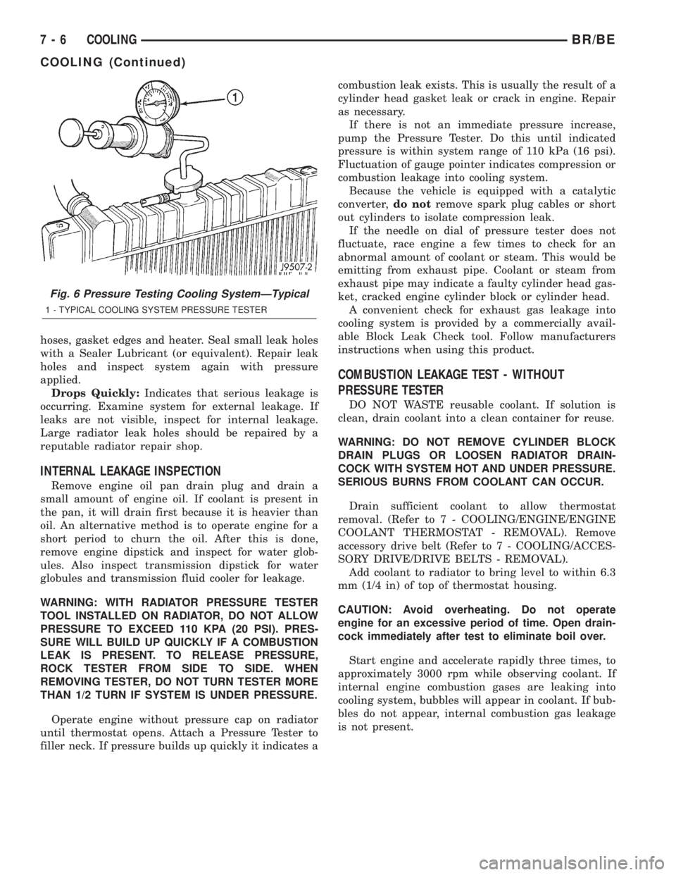
Fig. 6 Pressure Testing Cooling SystemÐTypical
1 - TYPICAL COOLING SYSTEM PRESSURE TESTER
7 - 6 COOLINGBR/BE
COOLING (Continued)
Page 309 of 2255
INSPECTION
Inspect the radiator side tanks for cracks, broken
or missing fittings also inspect the joint where the
tanks seam up to the radiator core for signs of leak-
age and/or deteriorating seals.
Inspect radiator core for corroded, bent or missing
cooling fins. Inspect the core for bent or damaged
cooling tubes.
INSTALLATION
(1) Position fan shroud over the fan blades rear-
ward towards engine.
(2) Install rubber insulators to alignment dowels
at lower part of radiator.
(3) Lower the radiator into position while guiding
the two alignment dowels into lower radiator sup-
port. Different alignment holes are provided in the
lower radiator support for each engine application.
(4) Install two upper radiator mounting bolts.
Tighten bolts to 11 N´m (95 in. lbs.) torque.
(5) Position the rubber shields to the sides of radi-
ator. Install the plastic clips retaining the rubber
shields to the sides of radiator.
(6) Connect both radiator hoses and install hose
clamps.
(7) Install windshield washer reservoir tank.
(8) Position fan shroud to flanges on sides of radi-
ator. Install fan shroud mounting bolts (Fig. 34).
Tighten bolts to 6 N´m (50 in. lbs.) torque.
(9) Install coolant reserve/overflow tank hose to
radiator filler neck nipple.
(10) Install coolant reserve/overflow tank to fan
shroud (fits into T-slots on shroud).
(11) Install battery negative cables.
(12) Position heater controls tofull heatposition.
(13) Fill cooling system with coolant (Refer to 7 -
COOLING - STANDARD PROCEDURE).
(14) Operate engine until it reaches normal tem-
perature. Check cooling system fluid levels.
RADIATOR - 8.0L
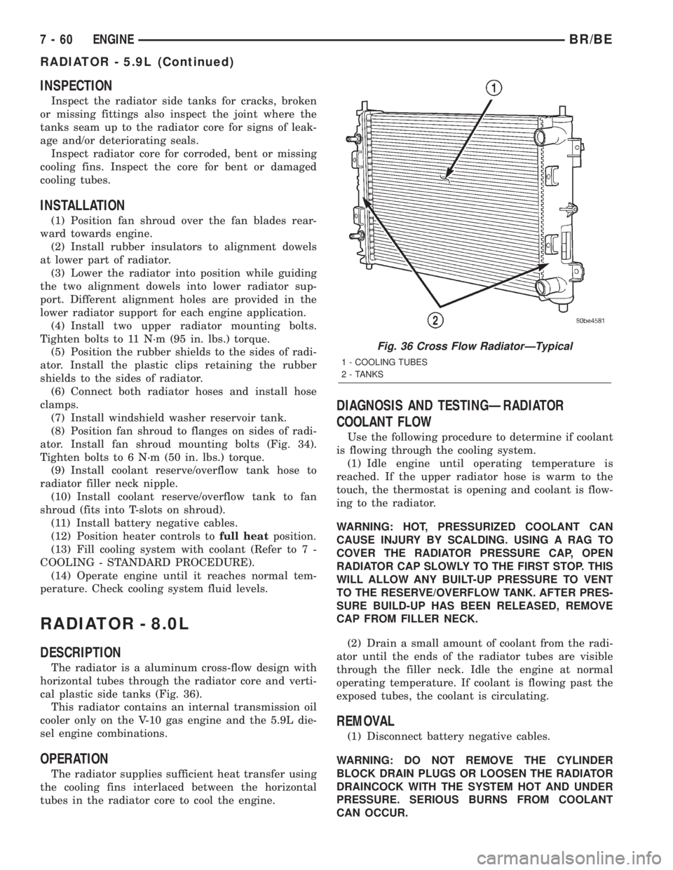
DESCRIPTION
The radiator is a aluminum cross-flow design with
horizontal tubes through the radiator core and verti-
cal plastic side tanks (Fig. 36).
This radiator contains an internal transmission oil
cooler only on the V-10 gas engine and the 5.9L die-
sel engine combinations.
OPERATION
The radiator supplies sufficient heat transfer using
the cooling fins interlaced between the horizontal
tubes in the radiator core to cool the engine.
DIAGNOSIS AND TESTINGÐRADIATOR
COOLANT FLOW
Use the following procedure to determine if coolant
is flowing through the cooling system.
(1) Idle engine until operating temperature is
reached. If the upper radiator hose is warm to the
touch, the thermostat is opening and coolant is flow-
ing to the radiator.
WARNING: HOT, PRESSURIZED COOLANT CAN
CAUSE INJURY BY SCALDING. USING A RAG TO
COVER THE RADIATOR PRESSURE CAP, OPEN
RADIATOR CAP SLOWLY TO THE FIRST STOP. THIS
WILL ALLOW ANY BUILT-UP PRESSURE TO VENT
TO THE RESERVE/OVERFLOW TANK. AFTER PRES-
SURE BUILD-UP HAS BEEN RELEASED, REMOVE
CAP FROM FILLER NECK.
(2) Drain a small amount of coolant from the radi-
ator until the ends of the radiator tubes are visible
through the filler neck. Idle the engine at normal
operating temperature. If coolant is flowing past the
exposed tubes, the coolant is circulating.
REMOVAL
(1) Disconnect battery negative cables.
WARNING: DO NOT REMOVE THE CYLINDER
BLOCK DRAIN PLUGS OR LOOSEN THE RADIATOR
DRAINCOCK WITH THE SYSTEM HOT AND UNDER
PRESSURE. SERIOUS BURNS FROM COOLANT
CAN OCCUR.
Fig. 36 Cross Flow RadiatorÐTypical
1 - COOLING TUBES
2 - TANKS
7 - 60 ENGINEBR/BE
RADIATOR - 5.9L (Continued)
Page 311 of 2255
(2) Install rubber insulators to alignment dowels
at lower part of radiator.
(3) Lower the radiator into position while guiding
the two alignment dowels into lower radiator sup-
port. Different alignment holes are provided in the
lower radiator support for each engine application.
(4) Install two upper radiator mounting bolts.
Tighten bolts to 11 N´m (95 in. lbs.) torque.
(5) Connect both radiator hoses and install hose
clamps.
(6) Install windshield washer reservoir tank.
(7) Position fan shroud to flanges on sides of radi-
ator. Install fan shroud mounting bolts (Fig. 37).
Tighten bolts to 6 N´m (50 in. lbs.) torque.
(8) Install coolant reserve/overflow tank hose to
radiator filler neck nipple.
(9) Connect the overflow hose to the radiator.
(10) Install battery negative cables.
(11) Position heater controls tofull heatposition.
(12) Fill cooling system with coolant (Refer to 7 -
COOLING - STANDARD PROCEDURE).
(13) Operate engine until it reaches normal tem-
perature. Check cooling system fluid levels.
RADIATOR - 5.9L DIESEL
DESCRIPTION
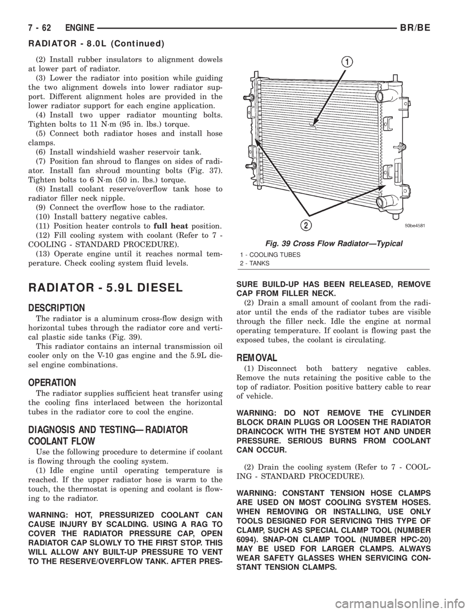
The radiator is a aluminum cross-flow design with
horizontal tubes through the radiator core and verti-
cal plastic side tanks (Fig. 39).
This radiator contains an internal transmission oil
cooler only on the V-10 gas engine and the 5.9L die-
sel engine combinations.
OPERATION
The radiator supplies sufficient heat transfer using
the cooling fins interlaced between the horizontal
tubes in the radiator core to cool the engine.
DIAGNOSIS AND TESTINGÐRADIATOR
COOLANT FLOW
Use the following procedure to determine if coolant
is flowing through the cooling system.
(1) Idle engine until operating temperature is
reached. If the upper radiator hose is warm to the
touch, the thermostat is opening and coolant is flow-
ing to the radiator.
WARNING: HOT, PRESSURIZED COOLANT CAN
CAUSE INJURY BY SCALDING. USING A RAG TO
COVER THE RADIATOR PRESSURE CAP, OPEN
RADIATOR CAP SLOWLY TO THE FIRST STOP. THIS
WILL ALLOW ANY BUILT-UP PRESSURE TO VENT
TO THE RESERVE/OVERFLOW TANK. AFTER PRES-SURE BUILD-UP HAS BEEN RELEASED, REMOVE
CAP FROM FILLER NECK.
(2) Drain a small amount of coolant from the radi-
ator until the ends of the radiator tubes are visible
through the filler neck. Idle the engine at normal
operating temperature. If coolant is flowing past the
exposed tubes, the coolant is circulating.
REMOVAL
(1) Disconnect both battery negative cables.
Remove the nuts retaining the positive cable to the
top of radiator. Position positive battery cable to rear
of vehicle.
WARNING: DO NOT REMOVE THE CYLINDER
BLOCK DRAIN PLUGS OR LOOSEN THE RADIATOR
DRAINCOCK WITH THE SYSTEM HOT AND UNDER
PRESSURE. SERIOUS BURNS FROM COOLANT
CAN OCCUR.
(2) Drain the cooling system (Refer to 7 - COOL-
ING - STANDARD PROCEDURE).
WARNING: CONSTANT TENSION HOSE CLAMPS
ARE USED ON MOST COOLING SYSTEM HOSES.
WHEN REMOVING OR INSTALLING, USE ONLY
TOOLS DESIGNED FOR SERVICING THIS TYPE OF
CLAMP, SUCH AS SPECIAL CLAMP TOOL (NUMBER
6094). SNAP-ON CLAMP TOOL (NUMBER HPC-20)
MAY BE USED FOR LARGER CLAMPS. ALWAYS
WEAR SAFETY GLASSES WHEN SERVICING CON-
STANT TENSION CLAMPS.
Fig. 39 Cross Flow RadiatorÐTypical
1 - COOLING TUBES
2 - TANKS
7 - 62 ENGINEBR/BE
RADIATOR - 8.0L (Continued)
Page 313 of 2255
CLEANING
Clean radiator fins are necessary for good heat
transfer. The radiator and air conditioning fins
should be cleaned when an accumulation of debris
has occurred. With the engine cold, apply cold water
and compressed air to the back (engine side) of the
radiator to flush the radiator and/or A/C condenser of
debris.
INSPECTION
Inspect the radiator side tanks for cracks, broken
or missing fittings also inspect the joint where the
tanks seam up to the radiator core for signs of leak-
age and/or deteriorating seals.
Inspect radiator core for corroded, bent or missing
cooling fins. Inspect the core for bent or damaged
cooling tubes.
INSTALLATION
(1) Position fan shroud over the fan blades rear-
ward towards engine.
(2) Install rubber insulators to alignment dowels
at lower part of radiator.
(3) Lower the radiator into position while guiding
the two alignment dowels into lower radiator sup-
port. Different alignment holes are provided in the
lower radiator support for each engine application.
(4) Install two upper radiator mounting bolts.
Tighten bolts to 11 N´m (95 in. lbs.) torque.
(5) Connect both radiator hoses and install hose
clamps.
(6) Connect transmission cooler lines to radiator
tank. Inspect quick connect fittings for debris and
install until an audible ªclickº is heard. Pull apart to
verify connection.
(7) Install windshield washer reservoir tank.
(8) Position fan shroud to flanges on sides of radi-
ator. Install fan shroud mounting bolts (Fig. 41).
Tighten bolts to 6 N´m (50 in. lbs.) torque.
(9) Install metal clips to top of fan shroud.
(10) Install coolant reserve/overflow tank hose to
radiator filler neck nipple.
(11) Install coolant reserve/overflow tank to fan
shroud (fits into T-slots on shroud).
(12) Install battery negative cables.
(13) Install positive battery cable to top of radia-
tor. Tighten radiator-to-battery cable mounting nuts.
(14) Position heater controls tofull heatposition.
(15) Fill cooling system with coolant (Refer to 7 -
COOLING - STANDARD PROCEDURE).
(16) Operate engine until it reaches normal tem-
perature. Check cooling system and automatic trans-
mission (if equipped) fluid levels.
RADIATOR PRESSURE CAP
DESCRIPTION
Radiators are equipped with a pressure cap, which
releases pressure at some point within a range of
97-124 kPa (14-18 psi). The pressure relief point (in
pounds) is engraved on top of cap.
The cooling system will operate at pressures
slightly above atmospheric pressure. This results in a
higher coolant boiling point allowing increased radi-
ator cooling capacity.
A rubber gasket seals radiator filler neck to pre-
vent leakage. This is done to keep system under
pressure. It also maintains vacuum during coolant
cool-down allowing coolant to return from reserve/
overflow tank.
OPERATION
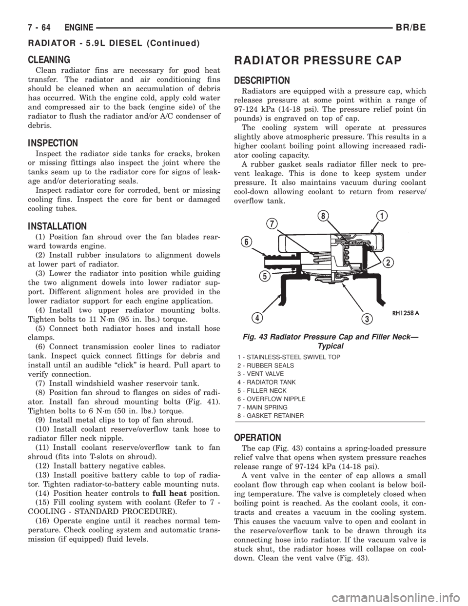
The cap (Fig. 43) contains a spring-loaded pressure
relief valve that opens when system pressure reaches
release range of 97-124 kPa (14-18 psi).
A vent valve in the center of cap allows a small
coolant flow through cap when coolant is below boil-
ing temperature. The valve is completely closed when
boiling point is reached. As the coolant cools, it con-
tracts and creates a vacuum in the cooling system.
This causes the vacuum valve to open and coolant in
the reserve/overflow tank to be drawn through its
connecting hose into radiator. If the vacuum valve is
stuck shut, the radiator hoses will collapse on cool-
down. Clean the vent valve (Fig. 43).
Fig. 43 Radiator Pressure Cap and Filler NeckÐ
Typical
1 - STAINLESS-STEEL SWIVEL TOP
2 - RUBBER SEALS
3 - VENT VALVE
4 - RADIATOR TANK
5 - FILLER NECK
6 - OVERFLOW NIPPLE
7 - MAIN SPRING
8 - GASKET RETAINER
7 - 64 ENGINEBR/BE
RADIATOR - 5.9L DIESEL (Continued)