towing DODGE RAM 2002 Service Repair Manual
[x] Cancel search | Manufacturer: DODGE, Model Year: 2002, Model line: RAM, Model: DODGE RAM 2002Pages: 2255, PDF Size: 62.07 MB
Page 14 of 2255
LUBRICATION & MAINTENANCE
TABLE OF CONTENTS
page page
INTERNATIONAL SYMBOLS
DESCRIPTION...........................1
PARTS & LUBRICANT RECOMMENDATION
STANDARD PROCEDURE
STANDARD PROCEDURE -
CLASSIFICATION OF LUBRICANTS..........1
FLUID TYPES
DESCRIPTION...........................2
OPERATION.............................6
FLUID CAPACITIES
SPECIFICATIONS.........................6
MAINTENANCE SCHEDULES
DESCRIPTION...........................7JUMP STARTING
STANDARD PROCEDURE
STANDARD PROCEDURE - JUMP
STARTING.............................7
HOISTING
STANDARD PROCEDURE
STANDARD PROCEDURE - HOISTING.......9
TOWING
STANDARD PROCEDURE
STANDARD PROCEDURE - TOWING.......10
INTERNATIONAL SYMBOLS
DESCRIPTION
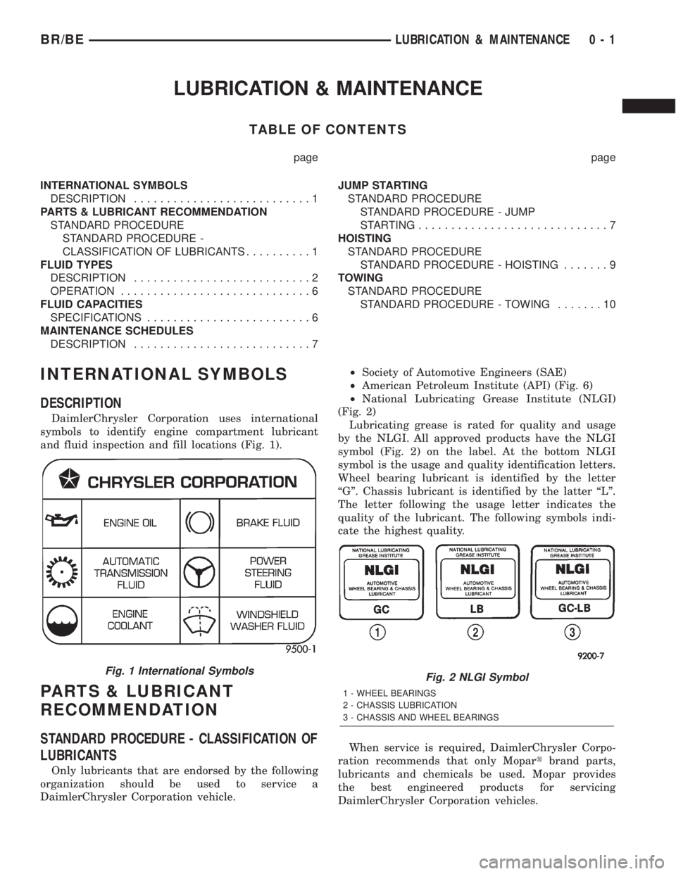
DaimlerChrysler Corporation uses international
symbols to identify engine compartment lubricant
and fluid inspection and fill locations (Fig. 1).
PARTS & LUBRICANT
RECOMMENDATION
STANDARD PROCEDURE - CLASSIFICATION OF
LUBRICANTS
Only lubricants that are endorsed by the following
organization should be used to service a
DaimlerChrysler Corporation vehicle.²Society of Automotive Engineers (SAE)
²American Petroleum Institute (API) (Fig. 6)
²National Lubricating Grease Institute (NLGI)
(Fig. 2)
Lubricating grease is rated for quality and usage
by the NLGI. All approved products have the NLGI
symbol (Fig. 2) on the label. At the bottom NLGI
symbol is the usage and quality identification letters.
Wheel bearing lubricant is identified by the letter
ªGº. Chassis lubricant is identified by the latter ªLº.
The letter following the usage letter indicates the
quality of the lubricant. The following symbols indi-
cate the highest quality.
When service is required, DaimlerChrysler Corpo-
ration recommends that only Mopartbrand parts,
lubricants and chemicals be used. Mopar provides
the best engineered products for servicing
DaimlerChrysler Corporation vehicles.
Fig. 1 International SymbolsFig. 2 NLGI Symbol
1 - WHEEL BEARINGS
2 - CHASSIS LUBRICATION
3 - CHASSIS AND WHEEL BEARINGS
BR/BELUBRICATION & MAINTENANCE 0 - 1
Page 23 of 2255
TOWING
STANDARD PROCEDURE - TOWING
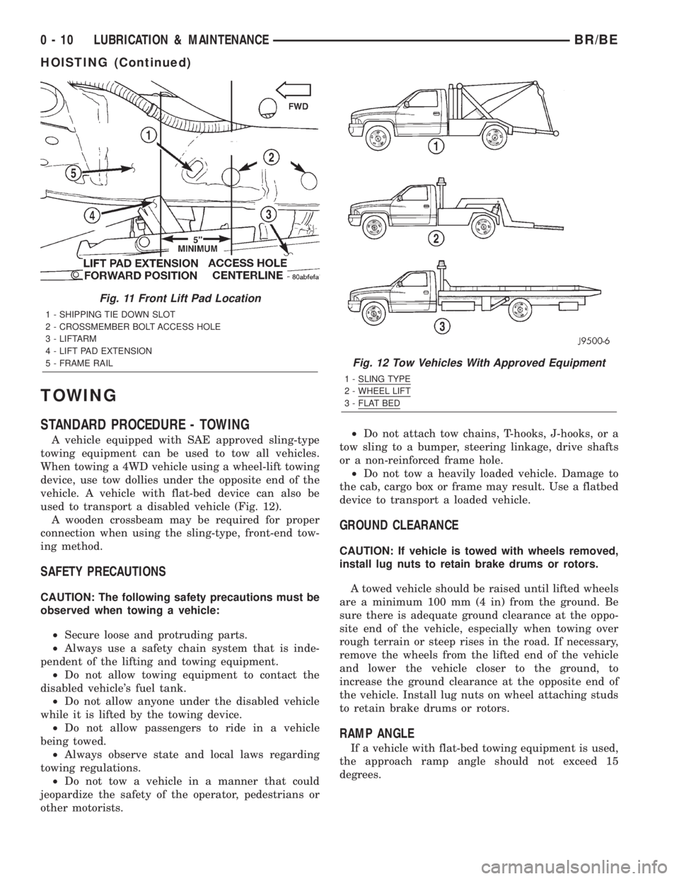
A vehicle equipped with SAE approved sling-type
towing equipment can be used to tow all vehicles.
When towing a 4WD vehicle using a wheel-lift towing
device, use tow dollies under the opposite end of the
vehicle. A vehicle with flat-bed device can also be
used to transport a disabled vehicle (Fig. 12).
A wooden crossbeam may be required for proper
connection when using the sling-type, front-end tow-
ing method.
SAFETY PRECAUTIONS
CAUTION: The following safety precautions must be
observed when towing a vehicle:
²Secure loose and protruding parts.
²Always use a safety chain system that is inde-
pendent of the lifting and towing equipment.
²Do not allow towing equipment to contact the
disabled vehicle's fuel tank.
²Do not allow anyone under the disabled vehicle
while it is lifted by the towing device.
²Do not allow passengers to ride in a vehicle
being towed.
²Always observe state and local laws regarding
towing regulations.
²Do not tow a vehicle in a manner that could
jeopardize the safety of the operator, pedestrians or
other motorists.²Do not attach tow chains, T-hooks, J-hooks, or a
tow sling to a bumper, steering linkage, drive shafts
or a non-reinforced frame hole.
²Do not tow a heavily loaded vehicle. Damage to
the cab, cargo box or frame may result. Use a flatbed
device to transport a loaded vehicle.
GROUND CLEARANCE
CAUTION: If vehicle is towed with wheels removed,
install lug nuts to retain brake drums or rotors.
A towed vehicle should be raised until lifted wheels
are a minimum 100 mm (4 in) from the ground. Be
sure there is adequate ground clearance at the oppo-
site end of the vehicle, especially when towing over
rough terrain or steep rises in the road. If necessary,
remove the wheels from the lifted end of the vehicle
and lower the vehicle closer to the ground, to
increase the ground clearance at the opposite end of
the vehicle. Install lug nuts on wheel attaching studs
to retain brake drums or rotors.
RAMP ANGLE
If a vehicle with flat-bed towing equipment is used,
the approach ramp angle should not exceed 15
degrees.
Fig. 11 Front Lift Pad Location
1 - SHIPPING TIE DOWN SLOT
2 - CROSSMEMBER BOLT ACCESS HOLE
3 - LIFTARM
4 - LIFT PAD EXTENSION
5 - FRAME RAIL
Fig. 12 Tow Vehicles With Approved Equipment
1 - SLING TYPE
2 - WHEEL LIFT
3 - FLAT BED
0 - 10 LUBRICATION & MAINTENANCEBR/BE
HOISTING (Continued)
Page 24 of 2255
TOWING WHEN KEYS ARE NOT AVAILABLE
When the vehicle is locked and keys are not avail-
able, use a flat bed hauler. A Wheel-lift or Sling-type
device can be used on 4WD vehicles providedall the
wheels are lifted off the ground using tow dol-
lies.
FOUR-WHEEL-DRIVE VEHICLE TOWING
Chrysler Corporation recommends that a vehicle be
transported on a flat-bed device. A Wheel-lift or
Sling-type device can be used providedall the
wheels are lifted off the ground using tow dol-
lies.WARNING: WHEN TOWING A DISABLED VEHICLE
AND THE DRIVE WHEELS ARE SECURED IN A
WHEEL LIFT OR TOW DOLLIES, ENSURE THE
TRANSMISSION IS IN THE PARK POSITION (AUTO-
MATIC TRANSMISSION) OR A FORWARD DRIVE
GEAR (MANUAL TRANSMISSION).
CAUTION: Many vehicles are equipped with air
dams, spoilers, and/or ground effect panels. To
avoid component damage, a wheel-lift towing vehi-
cle or a flat-bed hauling vehicle is recommended.
BR/BELUBRICATION & MAINTENANCE 0 - 11
TOWING (Continued)
Page 250 of 2255
COOLING
TABLE OF CONTENTS
page page
COOLING
DESCRIPTION
DESCRIPTION - COOLING SYSTEM FLOW -
5.9L ENGINE..........................1
DESCRIPTIONÐCOOLING SYSTEM FLOW -
5.9L DIESEL..........................2
DESCRIPTIONÐHOSE CLAMPS...........4
OPERATION
OPERATIONÐHOSE CLAMPS............4
OPERATIONÐCOOLING SYSTEM.........4
DIAGNOSIS AND TESTING
DIAGNOSIS AND TESTING - PRELIMINARY
CHECKS.............................4
DIAGNOSIS AND TESTINGÐON-BOARD
DIAGNOSTICS (OBD)...................5
DIAGNOSIS AND TESTING - COOLING
SYSTEM LEAKS.......................5
DIAGNOSIS AND TESTING - COOLING
SYSTEM GAS ENGINE..................7
DIAGNOSIS AND TESTING - COOLING
SYSTEM DIESEL ENGINE...............13
STANDARD PROCEDURE
STANDARD PROCEDURE - DRAINING
COOLING SYSTEM 5.9L/8.0L ENGINES....15STANDARD PROCEDUREÐDRAINING
COOLING SYSTEM 5.9L DIESEL ENGINE . . . 15
STANDARD PROCEDURE - REFILLING
COOLING SYSTEM 5.9L/8.0L ENGINES....16
STANDARD PROCEDUREÐREFILLING
COOLING SYSTEM 5.9L DIESEL ENGINE . . . 16
STANDARD PROCEDURE - ADDING
ADDITIONAL COOLANT.................16
STANDARD PROCEDUREÐCOOLANT
LEVEL CHECK........................16
STANDARD PROCEDURE - COOLING
SYSTEM CLEANING/REVERSE FLUSHING . . 17
STANDARD PROCEDURE - COOLANT
SELECTION - ADDITIVES...............17
SPECIFICATIONS
TORQUE............................18
SPECIAL TOOLS
COOLING...........................18
ACCESSORY DRIVE......................19
ENGINE...............................38
TRANSMISSION.........................78
COOLING
DESCRIPTION
DESCRIPTION - COOLING SYSTEM FLOW -
5.9L ENGINE
The cooling system regulates engine operating tem-
perature. It allows the engine to reach normal oper-
ating temperature as quickly as possible. It also
maintains normal operating temperature and pre-
vents overheating.The cooling system also provides a means of heat-
ing the passenger compartment and cooling the auto-
matic transmission fluid (if equipped). The cooling
system is pressurized and uses a centrifugal water
pump to circulate coolant throughout the system.
An optional factory installed maximum duty cool-
ing package is available on most models. This pack-
age will provide additional cooling capacity for
vehicles used under extreme conditions such as
trailer towing in high ambient temperatures (Fig. 1).
BR/BECOOLING 7 - 1
Page 253 of 2255
DESCRIPTIONÐHOSE CLAMPS
The cooling system utilizes both worm drive and
spring type hose clamps. If a spring type clamp
replacement is necessary, replace with the original
Mopartequipment spring type clamp.
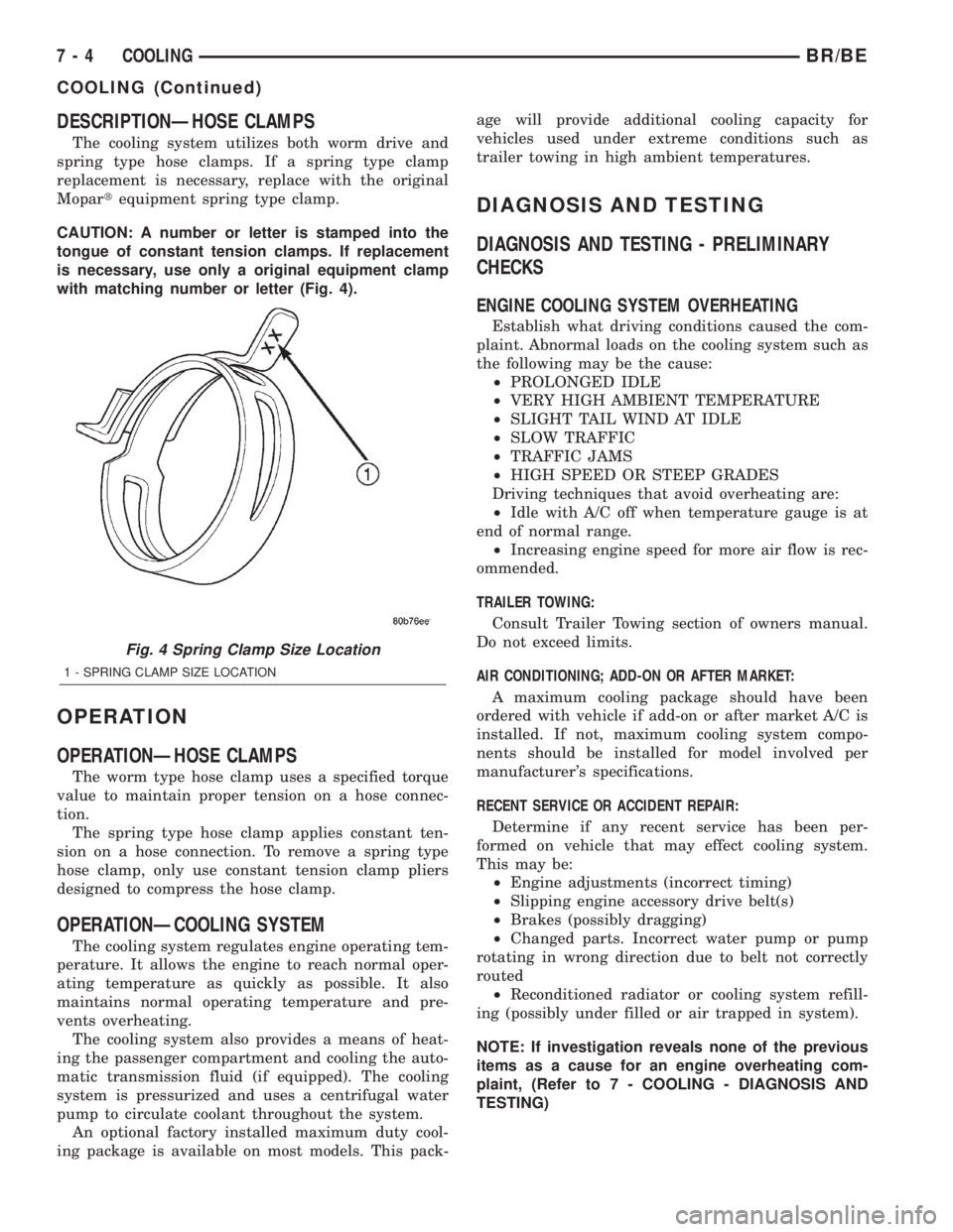
CAUTION: A number or letter is stamped into the
tongue of constant tension clamps. If replacement
is necessary, use only a original equipment clamp
with matching number or letter (Fig. 4).
OPERATION
OPERATIONÐHOSE CLAMPS
The worm type hose clamp uses a specified torque
value to maintain proper tension on a hose connec-
tion.
The spring type hose clamp applies constant ten-
sion on a hose connection. To remove a spring type
hose clamp, only use constant tension clamp pliers
designed to compress the hose clamp.
OPERATIONÐCOOLING SYSTEM
The cooling system regulates engine operating tem-
perature. It allows the engine to reach normal oper-
ating temperature as quickly as possible. It also
maintains normal operating temperature and pre-
vents overheating.
The cooling system also provides a means of heat-
ing the passenger compartment and cooling the auto-
matic transmission fluid (if equipped). The cooling
system is pressurized and uses a centrifugal water
pump to circulate coolant throughout the system.
An optional factory installed maximum duty cool-
ing package is available on most models. This pack-age will provide additional cooling capacity for
vehicles used under extreme conditions such as
trailer towing in high ambient temperatures.
DIAGNOSIS AND TESTING
DIAGNOSIS AND TESTING - PRELIMINARY
CHECKS
ENGINE COOLING SYSTEM OVERHEATING
Establish what driving conditions caused the com-
plaint. Abnormal loads on the cooling system such as
the following may be the cause:
²PROLONGED IDLE
²VERY HIGH AMBIENT TEMPERATURE
²SLIGHT TAIL WIND AT IDLE
²SLOW TRAFFIC
²TRAFFIC JAMS
²HIGH SPEED OR STEEP GRADES
Driving techniques that avoid overheating are:
²Idle with A/C off when temperature gauge is at
end of normal range.
²Increasing engine speed for more air flow is rec-
ommended.
TRAILER TOWING:
Consult Trailer Towing section of owners manual.
Do not exceed limits.
AIR CONDITIONING; ADD-ON OR AFTER MARKET:
A maximum cooling package should have been
ordered with vehicle if add-on or after market A/C is
installed. If not, maximum cooling system compo-
nents should be installed for model involved per
manufacturer's specifications.
RECENT SERVICE OR ACCIDENT REPAIR:
Determine if any recent service has been per-
formed on vehicle that may effect cooling system.
This may be:
²Engine adjustments (incorrect timing)
²Slipping engine accessory drive belt(s)
²Brakes (possibly dragging)
²Changed parts. Incorrect water pump or pump
rotating in wrong direction due to belt not correctly
routed
²Reconditioned radiator or cooling system refill-
ing (possibly under filled or air trapped in system).
NOTE: If investigation reveals none of the previous
items as a cause for an engine overheating com-
plaint, (Refer to 7 - COOLING - DIAGNOSIS AND
TESTING)
Fig. 4 Spring Clamp Size Location
1 - SPRING CLAMP SIZE LOCATION
7 - 4 COOLINGBR/BE
COOLING (Continued)
Page 304 of 2255
FAN DRIVE VISCOUS CLUTCH
- 5.9L/8.0L
DESCRIPTION
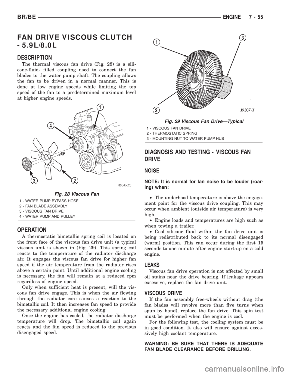
The thermal viscous fan drive (Fig. 28) is a sili-
cone-fluid- filled coupling used to connect the fan
blades to the water pump shaft. The coupling allows
the fan to be driven in a normal manner. This is
done at low engine speeds while limiting the top
speed of the fan to a predetermined maximum level
at higher engine speeds.
OPERATION
A thermostatic bimetallic spring coil is located on
the front face of the viscous fan drive unit (a typical
viscous unit is shown in (Fig. 29). This spring coil
reacts to the temperature of the radiator discharge
air. It engages the viscous fan drive for higher fan
speed if the air temperature from the radiator rises
above a certain point. Until additional engine cooling
is necessary, the fan will remain at a reduced rpm
regardless of engine speed.
Only when sufficient heat is present, will the vis-
cous fan drive engage. This is when the air flowing
through the radiator core causes a reaction to the
bimetallic coil. It then increases fan speed to provide
the necessary additional engine cooling.
Once the engine has cooled, the radiator discharge
temperature will drop. The bimetallic coil again
reacts and the fan speed is reduced to the previous
disengaged speed.
DIAGNOSIS AND TESTING - VISCOUS FAN
DRIVE
NOISE
NOTE: It is normal for fan noise to be louder (roar-
ing) when:
²The underhood temperature is above the engage-
ment point for the viscous drive coupling. This may
occur when ambient (outside air temperature) is very
high.
²Engine loads and temperatures are high such as
when towing a trailer.
²Cool silicone fluid within the fan drive unit is
being redistributed back to its normal disengaged
(warm) position. This can occur during the first 15
seconds to one minute after engine start-up on a cold
engine.
LEAKS
Viscous fan drive operation is not affected by small
oil stains near the drive bearing. If leakage appears
excessive, replace the fan drive unit.
VISCOUS DRIVE
If the fan assembly free-wheels without drag (the
fan blades will revolve more than five turns when
spun by hand), replace the fan drive. This spin test
must be performed when the engine is cool.
For the following test, the cooling system must be
in good condition. It also will ensure against exces-
sively high coolant temperature.
WARNING: BE SURE THAT THERE IS ADEQUATE
FAN BLADE CLEARANCE BEFORE DRILLING.
Fig. 28 Viscous Fan
1 - WATER PUMP BYPASS HOSE
2 - FAN BLADE ASSEMBLY
3 - VISCOUS FAN DRIVE
4 - WATER PUMP AND PULLEY
Fig. 29 Viscous Fan DriveÐTypical
1 - VISCOUS FAN DRIVE
2 - THERMOSTATIC SPRING
3 - MOUNTING NUT TO WATER PUMP HUB
BR/BEENGINE 7 - 55
Page 306 of 2255
bimetallic coil. It then increases fan speed to provide
the necessary additional engine cooling.
Once the engine has cooled, the radiator discharge
temperature will drop. The bimetallic coil again
reacts and the fan speed is reduced to the previous
disengaged speed.
DIAGNOSIS AND TESTING - VISCOUS FAN
DRIVE
NOISE
NOTE: It is normal for fan noise to be louder (roar-
ing) when:
²The underhood temperature is above the engage-
ment point for the viscous drive coupling. This may
occur when ambient (outside air temperature) is very
high.
²Engine loads and temperatures are high such as
when towing a trailer.
²Cool silicone fluid within the fan drive unit is
being redistributed back to its normal disengaged
(warm) position. This can occur during the first 15
seconds to one minute after engine start-up on a cold
engine.
LEAKS
Viscous fan drive operation is not affected by small
oil stains near the drive bearing. If leakage appears
excessive, replace the fan drive unit.
VISCOUS DRIVE
If the fan assembly free-wheels without drag (the
fan blades will revolve more than five turns whenspun by hand), replace the fan drive. This spin test
must be performed when the engine is cool.
For the following test, the cooling system must be
in good condition. It also will ensure against exces-
sively high coolant temperature.
WARNING: BE SURE THAT THERE IS ADEQUATE
FAN BLADE CLEARANCE BEFORE DRILLING.
(1) Drill a 3.18-mm (1/8-in) diameter hole in the
top center of the fan shroud.
(2) Obtain a dial thermometer with an 8 inch stem
(or equivalent). It should have a range of -18É-to-
105ÉC (0É-to-220É F). Insert thermometer through the
hole in the shroud. Be sure that there is adequate
clearance from the fan blades.
(3) Connect a tachometer and an engine ignition
timing light. The timing light is to be used as a
strobe light. This step cannot be used on the diesel
engine.
(4) Block the air flow through the radiator. Secure
a sheet of plastic in front of the radiator (or air con-
ditioner condenser). Use tape at the top to secure the
plastic and be sure that the air flow is blocked.
(5) Be sure that the air conditioner (if equipped) is
turned off.
WARNING: USE EXTREME CAUTION WHEN THE
ENGINE IS OPERATING. DO NOT STAND IN A
DIRECT LINE WITH THE FAN. DO NOT PUT YOUR
HANDS NEAR THE PULLEYS, BELTS OR FAN. DO
NOT WEAR LOOSE CLOTHING.
(6) Start the engine and operate at 2400 rpm.
Within ten minutes the air temperature (indicated on
the dial thermometer) should be up to 88É C (190É F).
Fan driveengagementshould start to occur at/be-
tween:
²5.9L gas engines Ð 79É C (175É F)
²8.0L engine Ð 88É to 96É C (190É to 205É F)
²5.9L diesel engine Ð 71É to 82É C (160É to 179É
F) Engagement is distinguishable by a definite
increasein fan flow noise (roaring). The timing light
also will indicate an increase in the speed of the fan
(non-diesel only).
(7) When viscous drive engagement is verified,
remove the plastic sheet. Fan drivedisengagement
should start to occur at between 57É to 79É C (135É to
175É F). A definitedecreaseof fan flow noise (roar-
ing) should be noticed. If not, replace the defective
viscous fan drive unit.
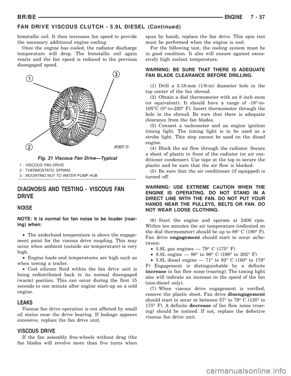
Fig. 31 Viscous Fan DriveÐTypical
1 - VISCOUS FAN DRIVE
2 - THERMOSTATIC SPRING
3 - MOUNTING NUT TO WATER PUMP HUB
BR/BEENGINE 7 - 57
FAN DRIVE VISCOUS CLUTCH - 5.9L DIESEL (Continued)
Page 522 of 2255
CLEARANCE LAMP
REMOVAL
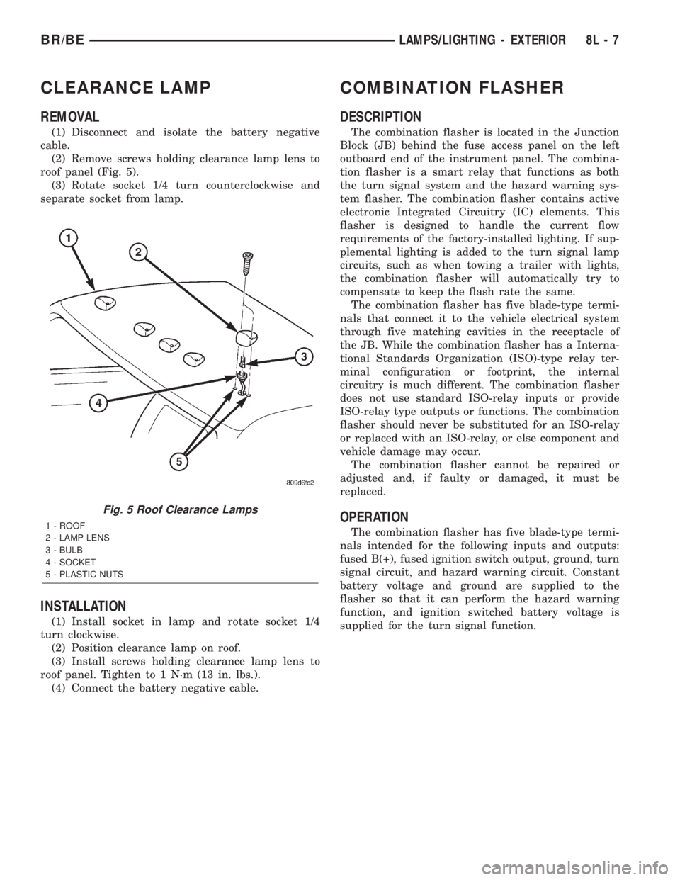
(1) Disconnect and isolate the battery negative
cable.
(2) Remove screws holding clearance lamp lens to
roof panel (Fig. 5).
(3) Rotate socket 1/4 turn counterclockwise and
separate socket from lamp.
INSTALLATION
(1) Install socket in lamp and rotate socket 1/4
turn clockwise.
(2) Position clearance lamp on roof.
(3) Install screws holding clearance lamp lens to
roof panel. Tighten to 1 N´m (13 in. lbs.).
(4) Connect the battery negative cable.
COMBINATION FLASHER
DESCRIPTION
The combination flasher is located in the Junction
Block (JB) behind the fuse access panel on the left
outboard end of the instrument panel. The combina-
tion flasher is a smart relay that functions as both
the turn signal system and the hazard warning sys-
tem flasher. The combination flasher contains active
electronic Integrated Circuitry (IC) elements. This
flasher is designed to handle the current flow
requirements of the factory-installed lighting. If sup-
plemental lighting is added to the turn signal lamp
circuits, such as when towing a trailer with lights,
the combination flasher will automatically try to
compensate to keep the flash rate the same.
The combination flasher has five blade-type termi-
nals that connect it to the vehicle electrical system
through five matching cavities in the receptacle of
the JB. While the combination flasher has a Interna-
tional Standards Organization (ISO)-type relay ter-
minal configuration or footprint, the internal
circuitry is much different. The combination flasher
does not use standard ISO-relay inputs or provide
ISO-relay type outputs or functions. The combination
flasher should never be substituted for an ISO-relay
or replaced with an ISO-relay, or else component and
vehicle damage may occur.
The combination flasher cannot be repaired or
adjusted and, if faulty or damaged, it must be
replaced.
OPERATION
The combination flasher has five blade-type termi-
nals intended for the following inputs and outputs:
fused B(+), fused ignition switch output, ground, turn
signal circuit, and hazard warning circuit. Constant
battery voltage and ground are supplied to the
flasher so that it can perform the hazard warning
function, and ignition switched battery voltage is
supplied for the turn signal function.
Fig. 5 Roof Clearance Lamps
1 - ROOF
2 - LAMP LENS
3 - BULB
4 - SOCKET
5 - PLASTIC NUTS
BR/BELAMPS/LIGHTING - EXTERIOR 8L - 7
Page 2249 of 2255
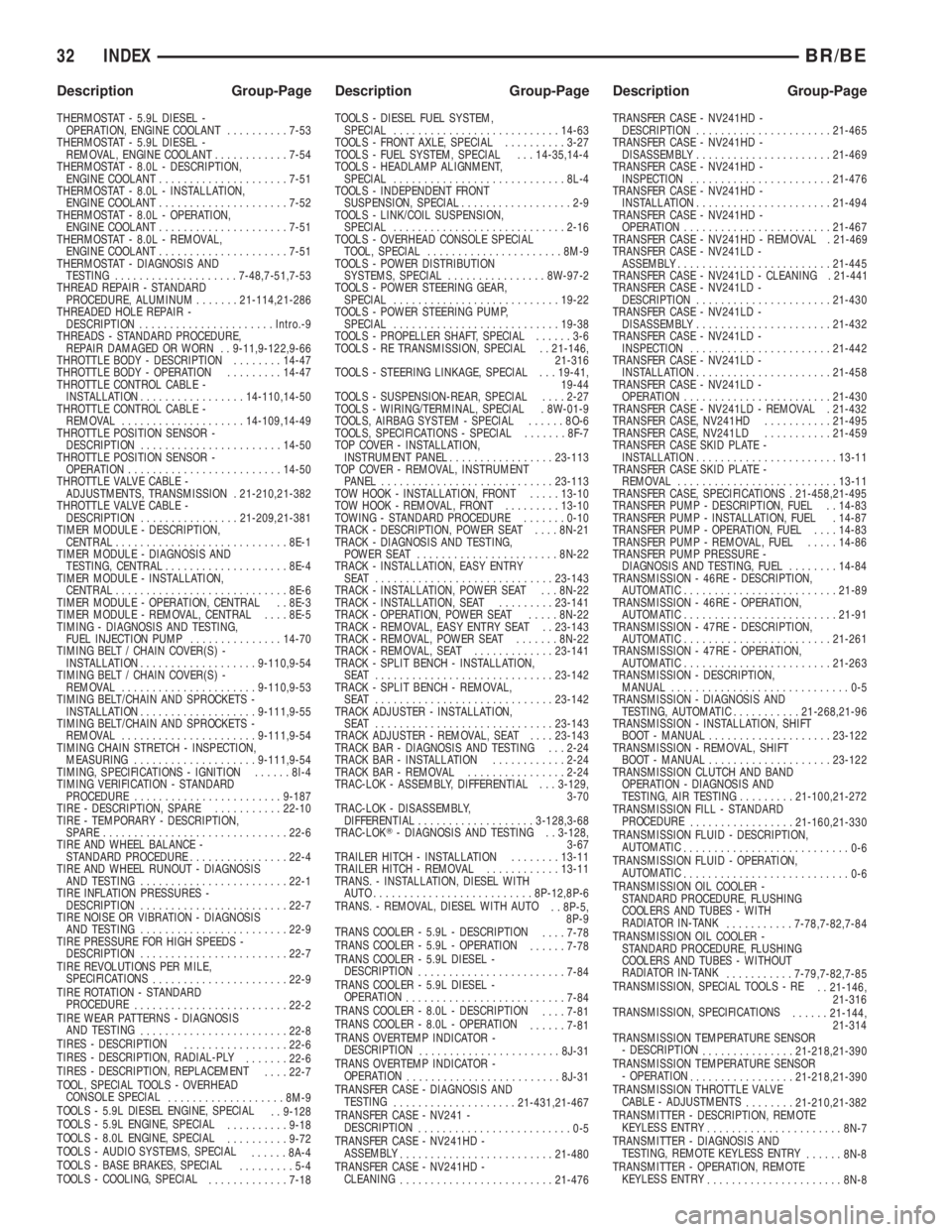
THERMOSTAT - 5.9L DIESEL -
OPERATION, ENGINE COOLANT..........7-53
THERMOSTAT - 5.9L DIESEL -
REMOVAL, ENGINE COOLANT............7-54
THERMOSTAT - 8.0L - DESCRIPTION,
ENGINE COOLANT.....................7-51
THERMOSTAT - 8.0L - INSTALLATION,
ENGINE COOLANT.....................7-52
THERMOSTAT - 8.0L - OPERATION,
ENGINE COOLANT.....................7-51
THERMOSTAT - 8.0L - REMOVAL,
ENGINE COOLANT.....................7-51
THERMOSTAT - DIAGNOSIS AND
TESTING....................7-48,7-51,7-53
THREAD REPAIR - STANDARD
PROCEDURE, ALUMINUM.......21-114,21-286
THREADED HOLE REPAIR -
DESCRIPTION......................Intro.-9
THREADS - STANDARD PROCEDURE,
REPAIR DAMAGED OR WORN . . 9-11,9-122,9-66
THROTTLE BODY - DESCRIPTION........14-47
THROTTLE BODY - OPERATION.........14-47
THROTTLE CONTROL CABLE -
INSTALLATION.................14-110,14-50
THROTTLE CONTROL CABLE -
REMOVAL....................14-109,14-49
THROTTLE POSITION SENSOR -
DESCRIPTION.......................14-50
THROTTLE POSITION SENSOR -
OPERATION.........................14-50
THROTTLE VALVE CABLE -
ADJUSTMENTS, TRANSMISSION . 21-210,21-382
THROTTLE VALVE CABLE -
DESCRIPTION................21-209,21-381
TIMER MODULE - DESCRIPTION,
CENTRAL............................8E-1
TIMER MODULE - DIAGNOSIS AND
TESTING, CENTRAL....................8E-4
TIMER MODULE - INSTALLATION,
CENTRAL............................8E-6
TIMER MODULE - OPERATION, CENTRAL . . 8E-3
TIMER MODULE - REMOVAL, CENTRAL....8E-5
TIMING - DIAGNOSIS AND TESTING,
FUEL INJECTION PUMP...............14-70
TIMING BELT / CHAIN COVER(S) -
INSTALLATION...................9-110,9-54
TIMING BELT / CHAIN COVER(S) -
REMOVAL......................9-110,9-53
TIMING BELT/CHAIN AND SPROCKETS -
INSTALLATION...................9-111,9-55
TIMING BELT/CHAIN AND SPROCKETS -
REMOVAL......................9-111,9-54
TIMING CHAIN STRETCH - INSPECTION,
MEASURING....................9-111,9-54
TIMING, SPECIFICATIONS - IGNITION......8I-4
TIMING VERIFICATION - STANDARD
PROCEDURE........................9-187
TIRE - DESCRIPTION, SPARE...........22-10
TIRE - TEMPORARY - DESCRIPTION,
SPARE..............................22-6
TIRE AND WHEEL BALANCE -
STANDARD PROCEDURE................22-4
TIRE AND WHEEL RUNOUT - DIAGNOSIS
AND TESTING........................22-1
TIRE INFLATION PRESSURES -
DESCRIPTION........................22-7
TIRE NOISE OR VIBRATION - DIAGNOSIS
AND TESTING........................22-9
TIRE PRESSURE FOR HIGH SPEEDS -
DESCRIPTION........................22-7
TIRE REVOLUTIONS PER MILE,
SPECIFICATIONS
......................22-9
TIRE ROTATION - STANDARD
PROCEDURE
.........................22-2
TIRE WEAR PATTERNS - DIAGNOSIS
AND TESTING
........................22-8
TIRES - DESCRIPTION
.................22-6
TIRES - DESCRIPTION, RADIAL-PLY
.......22-6
TIRES - DESCRIPTION, REPLACEMENT
....22-7
TOOL, SPECIAL TOOLS - OVERHEAD
CONSOLE SPECIAL
...................8M-9
TOOLS - 5.9L DIESEL ENGINE, SPECIAL
. . 9-128
TOOLS - 5.9L ENGINE, SPECIAL
..........9-18
TOOLS - 8.0L ENGINE, SPECIAL
..........9-72
TOOLS - AUDIO SYSTEMS, SPECIAL
......8A-4
TOOLS - BASE BRAKES, SPECIAL
.........5-4
TOOLS - COOLING, SPECIAL
.............7-18TOOLS - DIESEL FUEL SYSTEM,
SPECIAL...........................14-63
TOOLS - FRONT AXLE, SPECIAL..........3-27
TOOLS - FUEL SYSTEM, SPECIAL . . . 14-35,14-4
TOOLS - HEADLAMP ALIGNMENT,
SPECIAL............................8L-4
TOOLS - INDEPENDENT FRONT
SUSPENSION, SPECIAL..................2-9
TOOLS - LINK/COIL SUSPENSION,
SPECIAL............................2-16
TOOLS - OVERHEAD CONSOLE SPECIAL
TOOL, SPECIAL......................8M-9
TOOLS - POWER DISTRIBUTION
SYSTEMS, SPECIAL................8W-97-2
TOOLS - POWER STEERING GEAR,
SPECIAL...........................19-22
TOOLS - POWER STEERING PUMP,
SPECIAL...........................19-38
TOOLS - PROPELLER SHAFT, SPECIAL......3-6
TOOLS - RE TRANSMISSION, SPECIAL . . 21-146,
21-316
TOOLS - STEERING LINKAGE, SPECIAL . . . 19-41,
19-44
TOOLS - SUSPENSION-REAR, SPECIAL....2-27
TOOLS - WIRING/TERMINAL, SPECIAL . 8W-01-9
TOOLS, AIRBAG SYSTEM - SPECIAL......8O-6
TOOLS, SPECIFICATIONS - SPECIAL.......8F-7
TOP COVER - INSTALLATION,
INSTRUMENT PANEL.................23-113
TOP COVER - REMOVAL, INSTRUMENT
PANEL............................23-113
TOW HOOK - INSTALLATION, FRONT.....13-10
TOW HOOK - REMOVAL, FRONT.........13-10
TOWING - STANDARD PROCEDURE.......0-10
TRACK - DESCRIPTION, POWER SEAT....8N-21
TRACK - DIAGNOSIS AND TESTING,
POWER SEAT.......................8N-22
TRACK - INSTALLATION, EASY ENTRY
SEAT .............................23-143
TRACK - INSTALLATION, POWER SEAT . . . 8N-22
TRACK - INSTALLATION, SEAT.........23-141
TRACK - OPERATION, POWER SEAT.....8N-22
TRACK - REMOVAL, EASY ENTRY SEAT . . 23-143
TRACK - REMOVAL, POWER SEAT.......8N-22
TRACK - REMOVAL, SEAT.............23-141
TRACK - SPLIT BENCH - INSTALLATION,
SEAT .............................23-142
TRACK - SPLIT BENCH - REMOVAL,
SEAT .............................23-142
TRACK ADJUSTER - INSTALLATION,
SEAT .............................23-143
TRACK ADJUSTER - REMOVAL, SEAT....23-143
TRACK BAR - DIAGNOSIS AND TESTING . . . 2-24
TRACK BAR - INSTALLATION............2-24
TRACK BAR - REMOVAL................2-24
TRAC-LOK - ASSEMBLY, DIFFERENTIAL . . . 3-129,
3-70
TRAC-LOK - DISASSEMBLY,
DIFFERENTIAL...................3-128,3-68
TRAC-LOKT- DIAGNOSIS AND TESTING . . 3-128,
3-67
TRAILER HITCH - INSTALLATION........13-11
TRAILER HITCH - REMOVAL............13-11
TRANS. - INSTALLATION, DIESEL WITH
AUTO..........................8P-12,8P-6
TRANS. - REMOVAL, DIESEL WITH AUTO
. . 8P-5,
8P-9
TRANS COOLER - 5.9L - DESCRIPTION
....7-78
TRANS COOLER - 5.9L - OPERATION
......7-78
TRANS COOLER - 5.9L DIESEL -
DESCRIPTION
........................7-84
TRANS COOLER - 5.9L DIESEL -
OPERATION
..........................7-84
TRANS COOLER - 8.0L - DESCRIPTION
....7-81
TRANS COOLER - 8.0L - OPERATION
......7-81
TRANS OVERTEMP INDICATOR -
DESCRIPTION
.......................8J-31
TRANS OVERTEMP INDICATOR -
OPERATION
.........................8J-31
TRANSFER CASE - DIAGNOSIS AND
TESTING
....................21-431,21-467
TRANSFER CASE - NV241 -
DESCRIPTION
.........................0-5
TRANSFER CASE - NV241HD -
ASSEMBLY
.........................21-480
TRANSFER CASE - NV241HD -
CLEANING
.........................21-476TRANSFER CASE - NV241HD -
DESCRIPTION......................21-465
TRANSFER CASE - NV241HD -
DISASSEMBLY......................21-469
TRANSFER CASE - NV241HD -
INSPECTION.......................21-476
TRANSFER CASE - NV241HD -
INSTALLATION......................21-494
TRANSFER CASE - NV241HD -
OPERATION........................21-467
TRANSFER CASE - NV241HD - REMOVAL . 21-469
TRANSFER CASE - NV241LD -
ASSEMBLY.........................21-445
TRANSFER CASE - NV241LD - CLEANING . 21-441
TRANSFER CASE - NV241LD -
DESCRIPTION......................21-430
TRANSFER CASE - NV241LD -
DISASSEMBLY......................21-432
TRANSFER CASE - NV241LD -
INSPECTION.......................21-442
TRANSFER CASE - NV241LD -
INSTALLATION......................21-458
TRANSFER CASE - NV241LD -
OPERATION........................21-430
TRANSFER CASE - NV241LD - REMOVAL . 21-432
TRANSFER CASE, NV241HD...........21-495
TRANSFER CASE, NV241LD...........21-459
TRANSFER CASE SKID PLATE -
INSTALLATION.......................13-11
TRANSFER CASE SKID PLATE -
REMOVAL..........................13-11
TRANSFER CASE, SPECIFICATIONS . 21-458,21-495
TRANSFER PUMP - DESCRIPTION, FUEL . . 14-83
TRANSFER PUMP - INSTALLATION, FUEL . 14-87
TRANSFER PUMP - OPERATION, FUEL....14-83
TRANSFER PUMP - REMOVAL, FUEL.....14-86
TRANSFER PUMP PRESSURE -
DIAGNOSIS AND TESTING, FUEL........14-84
TRANSMISSION - 46RE - DESCRIPTION,
AUTOMATIC.........................21-89
TRANSMISSION - 46RE - OPERATION,
AUTOMATIC.........................21-91
TRANSMISSION - 47RE - DESCRIPTION,
AUTOMATIC........................21-261
TRANSMISSION - 47RE - OPERATION,
AUTOMATIC........................21-263
TRANSMISSION - DESCRIPTION,
MANUAL.............................0-5
TRANSMISSION - DIAGNOSIS AND
TESTING, AUTOMATIC...........21-268,21-96
TRANSMISSION - INSTALLATION, SHIFT
BOOT - MANUAL....................23-122
TRANSMISSION - REMOVAL, SHIFT
BOOT - MANUAL....................23-122
TRANSMISSION CLUTCH AND BAND
OPERATION - DIAGNOSIS AND
TESTING, AIR TESTING.........21-100,21-272
TRANSMISSION FILL - STANDARD
PROCEDURE
.................21-160,21-330
TRANSMISSION FLUID - DESCRIPTION,
AUTOMATIC
...........................0-6
TRANSMISSION FLUID - OPERATION,
AUTOMATIC
...........................0-6
TRANSMISSION OIL COOLER -
STANDARD PROCEDURE, FLUSHING
COOLERS AND TUBES - WITH
RADIATOR IN-TANK
...........7-78,7-82,7-84
TRANSMISSION OIL COOLER -
STANDARD PROCEDURE, FLUSHING
COOLERS AND TUBES - WITHOUT
RADIATOR IN-TANK
...........7-79,7-82,7-85
TRANSMISSION, SPECIAL TOOLS - RE
. . 21-146,
21-316
TRANSMISSION, SPECIFICATIONS
......21-144,
21-314
TRANSMISSION TEMPERATURE SENSOR
- DESCRIPTION
...............21-218,21-390
TRANSMISSION TEMPERATURE SENSOR
- OPERATION
.................21-218,21-390
TRANSMISSION THROTTLE VALVE
CABLE - ADJUSTMENTS
........21-210,21-382
TRANSMITTER - DESCRIPTION, REMOTE
KEYLESS ENTRY
......................8N-7
TRANSMITTER - DIAGNOSIS AND
TESTING, REMOTE KEYLESS ENTRY
......8N-8
TRANSMITTER - OPERATION, REMOTE
KEYLESS ENTRY
......................8N-8
32 INDEXBR/BE
Description Group-Page Description Group-Page Description Group-Page