brake fluid DODGE RAM 2002 Service Owner's Manual
[x] Cancel search | Manufacturer: DODGE, Model Year: 2002, Model line: RAM, Model: DODGE RAM 2002Pages: 2255, PDF Size: 62.07 MB
Page 224 of 2255
BRAKES - ABS
TABLE OF CONTENTS
page page
BRAKES - ABS
DESCRIPTION.........................35
OPERATION...........................36
DIAGNOSIS AND TESTING - ANTILOCK
BRAKES............................36
STANDARD PROCEDURE
STANDARD PROCEDURE - RWAL SERVICE
PRECAUTIONS.......................36
STANDARD PROCEDURE - BLEEDING ABS
BRAKE SYSTEM......................36
SPECIFICATIONS
TORQUE CHART......................37
FRONT WHEEL SPEED SENSOR
DESCRIPTION.........................38
OPERATION...........................38
REMOVAL
REMOVAL - 4X2......................39REMOVAL - 4X4......................39
INSTALLATION
INSTALLATION - 4X2...................39
INSTALLATION - 4X4...................39
REAR WHEEL SPEED SENSOR
DIAGNOSIS AND TESTING - REAR WHEEL
SPEED SENSOR......................40
REMOVAL.............................40
INSTALLATION.........................40
HCU (HYDRAULIC CONTROL UNIT)
DESCRIPTION.........................40
OPERATION...........................40
REMOVAL.............................41
INSTALLATION.........................41
BRAKES - ABS
DESCRIPTION
The antilock brake system (ABS) is an electroni-
cally operated, all wheel brake control system. 2500
and 3500 vehicles have Electronic Brake Distribution
(EBD) designed into the systen which eliminates the
combination/proportioning valve.
The system is designed to prevent wheel lockup
and maintain steering control during periods of high
wheel slip when braking. Preventing lockup is accom-
plished by modulating fluid pressure to the wheel
brake units.
The hydraulic system is a three channel design.
The front wheel brakes are controlled individually
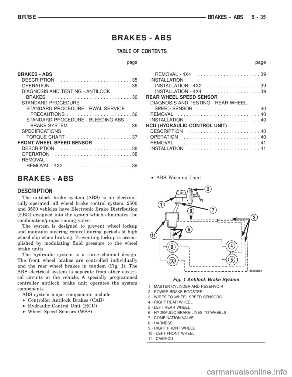
and the rear wheel brakes in tandem (Fig. 1). The
ABS electrical system is separate from other electri-
cal circuits in the vehicle. A specially programmed
controller antilock brake unit operates the system
components.
ABS system major components include:
²Controller Antilock Brakes (CAB)
²Hydraulic Control Unit (HCU)
²Wheel Speed Sensors (WSS)²ABS Warning Light
Fig. 1 Antilock Brake System
1 - MASTER CYLINDER AND RESERVOIR
2 - POWER BRAKE BOOSTER
3 - WIRES TO WHEEL SPEED SENSORS
4 - RIGHT REAR WHEEL
5 - LEFT REAR WHEEL
6 - HYDRAULIC BRAKE LINES TO WHEELS
7 - COMBINATION VALVE
8 - HARNESS
9 - RIGHT FRONT WHEEL
10 - LEFT FRONT WHEEL
11 - CAB/HCU
BR/BEBRAKES - ABS 5 - 35
Page 225 of 2255
OPERATION
Battery voltage is supplied to the CAB when a
speed of 15 miles per hour is reached. The CAB per-
forms a system initialization procedure at this point.
Initialization consists of a static and dynamic self
check of system electrical components.
The static and dynamic checks occurs at ignition
start up. During the dynamic check, the CAB briefly
cycles the pump and solenoids to verify operation. An
audible noise may be heard during this self check.
This noise should be considered normal.
If an ABS component exhibits a fault during ini-
tialization, the CAB illuminates the amber warning
light and registers a fault code in the microprocessor
memory.
The CAB monitors wheel speed sensor inputs con-
tinuously while the vehicle is in motion. However,
the CAB will not activate any ABS components as
long as sensor inputs indicate normal braking.
During normal braking, the master cylinder, power
booster and wheel brake units all function as they
would in a vehicle without ABS. The HCU compo-
nents are not activated.
The purpose of the antilock system is to prevent
wheel lockup during periods of high wheel slip. Pre-
venting lockup helps maintain vehicle braking action
and steering control.
The antilock CAB activates the system whenever
sensor signals indicate periods of wheel slip. Periods
of wheel slip occur when brake stops involve high
pedal pressure and rate of vehicle deceleration.
The antilock system prevents lockup during a
wheel slip condition by modulating fluid apply pres-
sure to the wheel brake units.
Brake fluid apply pressure is modulated according
to wheel speed, degree of slip and rate of decelera-
tion. Sensors at each front wheel convert wheel speed
into electrical signals. These signals are transmitted
to the CAB for processing and determination of
wheel slip and deceleration rate.
The ABS system has three fluid pressure control
channels. The front brakes are controlled separately
and the rear brakes in tandem. A speed sensor input
signal indicating a wheel slip condition activates the
CAB antilock program.
There are Two solenoid valves (Isolation and Dump
valve) which are used in each antilock control chan-
nel. The valves are all located within the HCU valve
body and work in pairs to either increase, hold, or
decrease apply pressure as needed in the individual
control channels.
During an ABS stop the ISO valve actuates, Stop-
ping anymore pressure build Ðup to the calipers.
Then the Dump valve dumps off pressure until the
wheel unlocks. This will continue until the wheels
quit slipping altogether.
DIAGNOSIS AND TESTING - ANTILOCK
BRAKES
The ABS brake system performs several self-tests
every time the ignition switch is turned on and the
vehicle is driven. The CAB monitors the systems
input and output circuits to verify the system is oper-
ating correctly. If the on board diagnostic system
senses that a circuit is malfunctioning the system
will set a trouble code in its memory.
NOTE: An audible noise may be heard during the
self-test. This noise should be considered normal.
NOTE: The MDS or DRB III scan tool is used to
diagnose the ABS system. For additional informa-
tion refer to the Antilock Brake section in Group
8W. For test procedures refer to the Chassis Diag-
nostic Manual.
STANDARD PROCEDURE
STANDARD PROCEDURE - RWAL SERVICE
PRECAUTIONS
The RWAL uses an electronic control module, the
CAB. This module is designed to withstand normal
current draws associated with vehicle operation.
Care must be taken to avoid overloading the CAB
circuits.In testing for open or short circuits, do
not ground or apply voltage to any of the cir-
cuits unless instructed to do so for a diagnostic
procedure.These circuits should only be tested
using a high impedance multi-meter or the DRB
tester as described in this section. Power should
never be removed or applied to any control module
with the ignition in the ON position. Before removing
or connecting battery cables, fuses, or connectors,
always turn the ignition to the OFF position.
CAUTION: Use only factory wiring harnesses. Do
not cut or splice wiring to the brake circuits. The
addition of after-market electrical equipment (car
phone, radar detector, citizen band radio, trailer
lighting, trailer brakes, ect.) on a vehicle equipped
with antilock brakes may affect the function of the
antilock brake system.
STANDARD PROCEDURE - BLEEDING ABS
BRAKE SYSTEM
ABS system bleeding requires conventional bleed-
ing methods plus use of the DRB scan tool. The pro-
cedure involves performing a base brake bleeding,
followed by use of the scan tool to cycle and bleed the
5 - 36 BRAKES - ABSBR/BE
BRAKES - ABS (Continued)
Page 226 of 2255
HCU pump and solenoids. A second base brake bleed-
ing procedure is then required to remove any air
remaining in the system.
(1) Perform the base brake bleeding, (Refer to 5 -
BRAKES/HYDRAULIC/MECHANICAL - STAN-
DARD PROCEDURE).
(2) Connect the scan tool to the Data Link Connec-
tor.(3) Select ANTILOCK BRAKES, followed by MIS-
CELLANEOUS, then ABS BRAKES. Follow the
instructions displayed. When scan tool displays TEST
COMPLETE, disconnect scan tool and proceed.
(4) Perform base brake bleeding a second time,
(Refer to 5 - BRAKES/HYDRAULIC/MECHANICAL -
STANDARD PROCEDURE).
(5) Top off master cylinder fluid level and verify
proper brake operation before moving vehicle.
SPECIFICATIONS
TORQUE CHART
TORQUE SPECIFICATIONS
DESCRIPTION N´m Ft. Lbs. In. Lbs.
ABS Assembly
Bracket Bolts13 10 120
ABS Assembly
Mounting Nuts13 10 102
ABS Assembly
CAB Screws4335
ABS Assembly
Brake Lines21 15 190
Wheel Speed Sensor
Frt. Bolts (4x2)23 17 200
Wheel Speed Sensor
Frt. Bolts (4x4)14 10 120
Wheel Speed Sensor
Rear Bolt24 18 210
BR/BEBRAKES - ABS 5 - 37
BRAKES - ABS (Continued)
Page 229 of 2255
NOTE: Check the sensor wire routing. Be sure the
wire is clear of all chassis components and is not
twisted or kinked at any spot.
(6) Install the tire and wheel assembly.
(7) Remove the support and lower the vehicle.
(8) Reconnect the ABS wheel speed sensor wire
electrical connector inside the engine compartment.
(9) Apply the brakes several times to seat the
brake shoes and caliper piston. Do not move the vehi-
cle until a firm brake pedal is obtained.
(10) Verify the wheel speed sensor operation with
a scan tool.
REAR WHEEL SPEED SENSOR
DIAGNOSIS AND TESTING - REAR WHEEL
SPEED SENSOR
Diagnosis of base brake conditions which are
mechanical in nature should be performed first. This
includes brake noise, lack of power assist, parking
brake, or vehicle vibration during normal braking.
The Antilock brake system performs several self-
tests every time the ignition switch is turned on and
the vehicle is driven. The CAB monitors the system
inputs and outputs circuits to verify the system is
operating properly. If the CAB senses a malfunction
in the system it will set a DTC into memory and trig-
ger the warning lamp.
NOTE: The MDS or DRB III scan tool is used to
diagnose the Antilock Brake system. For test proce-
dures refer to the Chassis Diagnostic Manual.
REMOVAL
(1) Raise vehicle on hoist.
(2) Remove brake line mounting nut and remove
the brake line from the sensor stud.
(3) Remove mounting stud from the sensor and
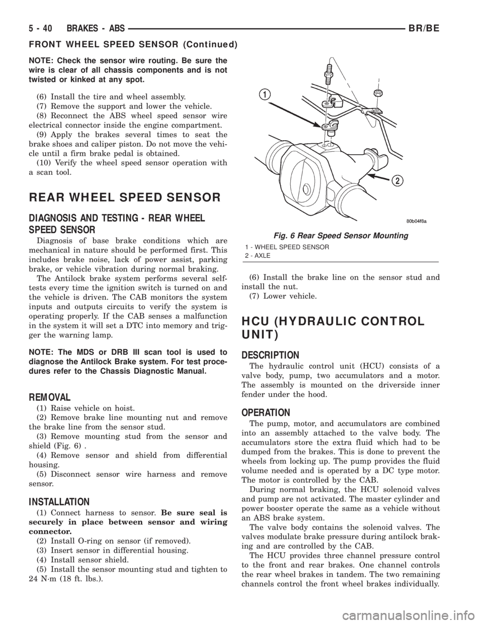
shield (Fig. 6) .
(4) Remove sensor and shield from differential
housing.
(5) Disconnect sensor wire harness and remove
sensor.
INSTALLATION
(1) Connect harness to sensor.Be sure seal is
securely in place between sensor and wiring
connector.
(2) Install O-ring on sensor (if removed).
(3) Insert sensor in differential housing.
(4) Install sensor shield.
(5) Install the sensor mounting stud and tighten to
24 N´m (18 ft. lbs.).(6) Install the brake line on the sensor stud and
install the nut.
(7) Lower vehicle.
HCU (HYDRAULIC CONTROL
UNIT)
DESCRIPTION
The hydraulic control unit (HCU) consists of a
valve body, pump, two accumulators and a motor.
The assembly is mounted on the driverside inner
fender under the hood.
OPERATION
The pump, motor, and accumulators are combined
into an assembly attached to the valve body. The
accumulators store the extra fluid which had to be
dumped from the brakes. This is done to prevent the
wheels from locking up. The pump provides the fluid
volume needed and is operated by a DC type motor.
The motor is controlled by the CAB.
During normal braking, the HCU solenoid valves
and pump are not activated. The master cylinder and
power booster operate the same as a vehicle without
an ABS brake system.
The valve body contains the solenoid valves. The
valves modulate brake pressure during antilock brak-
ing and are controlled by the CAB.
The HCU provides three channel pressure control
to the front and rear brakes. One channel controls
the rear wheel brakes in tandem. The two remaining
channels control the front wheel brakes individually.
Fig. 6 Rear Speed Sensor Mounting
1 - WHEEL SPEED SENSOR
2 - AXLE
5 - 40 BRAKES - ABSBR/BE
FRONT WHEEL SPEED SENSOR (Continued)
Page 230 of 2255
During antilock braking, the solenoid valves are
opened and closed as needed. The valves are not
static. They are cycled rapidly and continuously to
modulate pressure and control wheel slip and decel-
eration.
During antilock braking, solenoid valve pressure
modulation occurs in three stages, pressure decrease,
pressure hold, and pressure increase. The valves are
all contained in the valve body portion of the HCU.
PRESSURE DECREASE
The inlet valve is closed and the outlet valve is
opened during the pressure decrease cycle.
A pressure decrease cycle is initiated when speed
sensor signals indicate high wheel slip at one or
more wheels. At this point, the CAB closes the inlet
to prevent the driver from further increasing the
brake pressure and locking the brakes. The CAB
then opens the outlet valve, which also opens the
return circuit to the accumulators. Fluid pressure is
allowed to bleed off (decrease) as needed to prevent
wheel lock.
Once the period of high wheel slip has ended, the
CAB closes the outlet valve and begins a pressure
increase or hold cycle as needed.
PRESSURE HOLD
Both solenoid valves are closed in the pressure
hold cycle. Fluid apply pressure in the control chan-
nel is maintained at a constant rate. The CAB main-
tains the hold cycle until sensor inputs indicate a
pressure change is necessary.
PRESSURE INCREASE
The inlet valve is open and the outlet valve is
closed during the pressure increase cycle. The pres-
sure increase cycle is used to counteract unequal
wheel speeds. This cycle controls re-application of
fluid apply pressure due to changing road surfaces or
wheel speed.
REMOVAL
(1) Disconnect battery negative cable.
(2) Push the harness connector locks to release the
locks, then remove the connectors from the CAB.
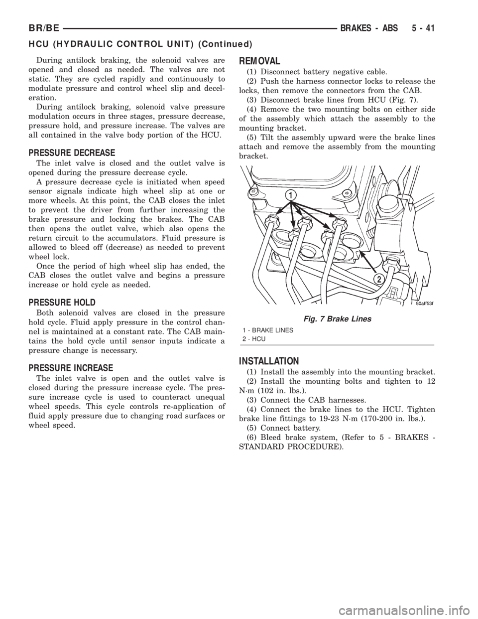
(3) Disconnect brake lines from HCU (Fig. 7).
(4) Remove the two mounting bolts on either side
of the assembly which attach the assembly to the
mounting bracket.
(5) Tilt the assembly upward were the brake lines
attach and remove the assembly from the mounting
bracket.
INSTALLATION
(1) Install the assembly into the mounting bracket.
(2) Install the mounting bolts and tighten to 12
N´m (102 in. lbs.).
(3) Connect the CAB harnesses.
(4) Connect the brake lines to the HCU. Tighten
brake line fittings to 19-23 N´m (170-200 in. lbs.).
(5) Connect battery.
(6) Bleed brake system, (Refer to 5 - BRAKES -
STANDARD PROCEDURE).
Fig. 7 Brake Lines
1 - BRAKE LINES
2 - HCU
BR/BEBRAKES - ABS 5 - 41
HCU (HYDRAULIC CONTROL UNIT) (Continued)
Page 253 of 2255
DESCRIPTIONÐHOSE CLAMPS
The cooling system utilizes both worm drive and
spring type hose clamps. If a spring type clamp
replacement is necessary, replace with the original
Mopartequipment spring type clamp.
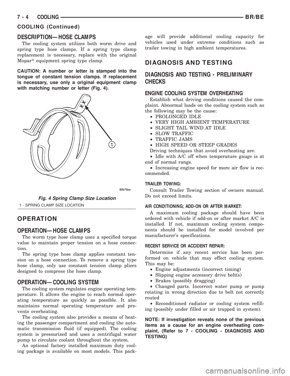
CAUTION: A number or letter is stamped into the
tongue of constant tension clamps. If replacement
is necessary, use only a original equipment clamp
with matching number or letter (Fig. 4).
OPERATION
OPERATIONÐHOSE CLAMPS
The worm type hose clamp uses a specified torque
value to maintain proper tension on a hose connec-
tion.
The spring type hose clamp applies constant ten-
sion on a hose connection. To remove a spring type
hose clamp, only use constant tension clamp pliers
designed to compress the hose clamp.
OPERATIONÐCOOLING SYSTEM
The cooling system regulates engine operating tem-
perature. It allows the engine to reach normal oper-
ating temperature as quickly as possible. It also
maintains normal operating temperature and pre-
vents overheating.
The cooling system also provides a means of heat-
ing the passenger compartment and cooling the auto-
matic transmission fluid (if equipped). The cooling
system is pressurized and uses a centrifugal water
pump to circulate coolant throughout the system.
An optional factory installed maximum duty cool-
ing package is available on most models. This pack-age will provide additional cooling capacity for
vehicles used under extreme conditions such as
trailer towing in high ambient temperatures.
DIAGNOSIS AND TESTING
DIAGNOSIS AND TESTING - PRELIMINARY
CHECKS
ENGINE COOLING SYSTEM OVERHEATING
Establish what driving conditions caused the com-
plaint. Abnormal loads on the cooling system such as
the following may be the cause:
²PROLONGED IDLE
²VERY HIGH AMBIENT TEMPERATURE
²SLIGHT TAIL WIND AT IDLE
²SLOW TRAFFIC
²TRAFFIC JAMS
²HIGH SPEED OR STEEP GRADES
Driving techniques that avoid overheating are:
²Idle with A/C off when temperature gauge is at
end of normal range.
²Increasing engine speed for more air flow is rec-
ommended.
TRAILER TOWING:
Consult Trailer Towing section of owners manual.
Do not exceed limits.
AIR CONDITIONING; ADD-ON OR AFTER MARKET:
A maximum cooling package should have been
ordered with vehicle if add-on or after market A/C is
installed. If not, maximum cooling system compo-
nents should be installed for model involved per
manufacturer's specifications.
RECENT SERVICE OR ACCIDENT REPAIR:
Determine if any recent service has been per-
formed on vehicle that may effect cooling system.
This may be:
²Engine adjustments (incorrect timing)
²Slipping engine accessory drive belt(s)
²Brakes (possibly dragging)
²Changed parts. Incorrect water pump or pump
rotating in wrong direction due to belt not correctly
routed
²Reconditioned radiator or cooling system refill-
ing (possibly under filled or air trapped in system).
NOTE: If investigation reveals none of the previous
items as a cause for an engine overheating com-
plaint, (Refer to 7 - COOLING - DIAGNOSIS AND
TESTING)
Fig. 4 Spring Clamp Size Location
1 - SPRING CLAMP SIZE LOCATION
7 - 4 COOLINGBR/BE
COOLING (Continued)
Page 258 of 2255
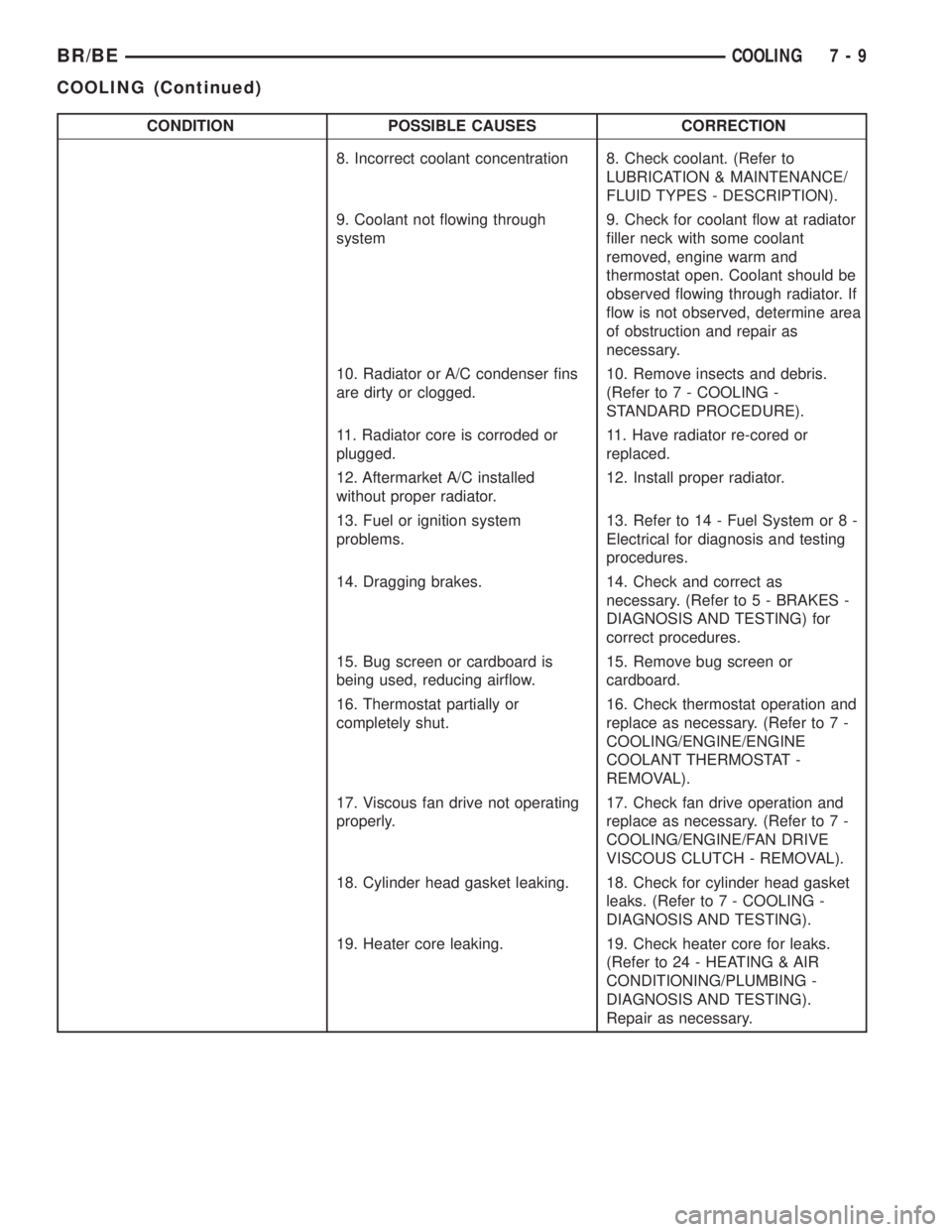
CONDITION POSSIBLE CAUSES CORRECTION
8. Incorrect coolant concentration 8. Check coolant. (Refer to
LUBRICATION & MAINTENANCE/
FLUID TYPES - DESCRIPTION).
9. Coolant not flowing through
system9. Check for coolant flow at radiator
filler neck with some coolant
removed, engine warm and
thermostat open. Coolant should be
observed flowing through radiator. If
flow is not observed, determine area
of obstruction and repair as
necessary.
10. Radiator or A/C condenser fins
are dirty or clogged.10. Remove insects and debris.
(Refer to 7 - COOLING -
STANDARD PROCEDURE).
11. Radiator core is corroded or
plugged.11. Have radiator re-cored or
replaced.
12. Aftermarket A/C installed
without proper radiator.12. Install proper radiator.
13. Fuel or ignition system
problems.13. Refer to 14 - Fuel System or 8 -
Electrical for diagnosis and testing
procedures.
14. Dragging brakes. 14. Check and correct as
necessary. (Refer to 5 - BRAKES -
DIAGNOSIS AND TESTING) for
correct procedures.
15. Bug screen or cardboard is
being used, reducing airflow.15. Remove bug screen or
cardboard.
16. Thermostat partially or
completely shut.16. Check thermostat operation and
replace as necessary. (Refer to 7 -
COOLING/ENGINE/ENGINE
COOLANT THERMOSTAT -
REMOVAL).
17. Viscous fan drive not operating
properly.17. Check fan drive operation and
replace as necessary. (Refer to 7 -
COOLING/ENGINE/FAN DRIVE
VISCOUS CLUTCH - REMOVAL).
18. Cylinder head gasket leaking. 18. Check for cylinder head gasket
leaks. (Refer to 7 - COOLING -
DIAGNOSIS AND TESTING).
19. Heater core leaking. 19. Check heater core for leaks.
(Refer to 24 - HEATING & AIR
CONDITIONING/PLUMBING -
DIAGNOSIS AND TESTING).
Repair as necessary.
BR/BECOOLING 7 - 9
COOLING (Continued)
Page 480 of 2255
INSTRUMENT CLUSTER
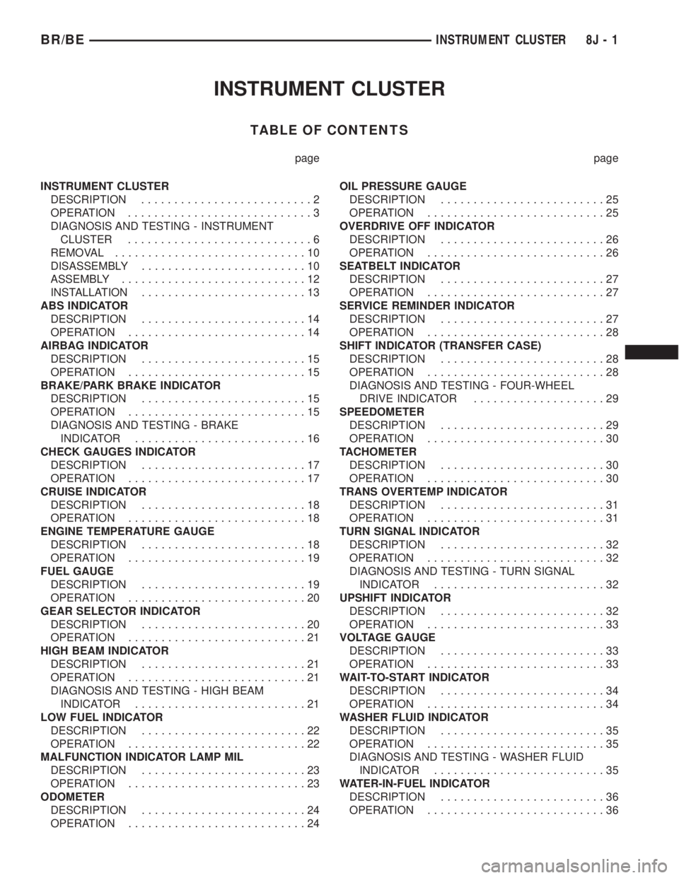
TABLE OF CONTENTS
page page
INSTRUMENT CLUSTER
DESCRIPTION..........................2
OPERATION............................3
DIAGNOSIS AND TESTING - INSTRUMENT
CLUSTER............................6
REMOVAL.............................10
DISASSEMBLY.........................10
ASSEMBLY............................12
INSTALLATION.........................13
ABS INDICATOR
DESCRIPTION.........................14
OPERATION...........................14
AIRBAG INDICATOR
DESCRIPTION.........................15
OPERATION...........................15
BRAKE/PARK BRAKE INDICATOR
DESCRIPTION.........................15
OPERATION...........................15
DIAGNOSIS AND TESTING - BRAKE
INDICATOR..........................16
CHECK GAUGES INDICATOR
DESCRIPTION.........................17
OPERATION...........................17
CRUISE INDICATOR
DESCRIPTION.........................18
OPERATION...........................18
ENGINE TEMPERATURE GAUGE
DESCRIPTION.........................18
OPERATION...........................19
FUEL GAUGE
DESCRIPTION.........................19
OPERATION...........................20
GEAR SELECTOR INDICATOR
DESCRIPTION.........................20
OPERATION...........................21
HIGH BEAM INDICATOR
DESCRIPTION.........................21
OPERATION...........................21
DIAGNOSIS AND TESTING - HIGH BEAM
INDICATOR..........................21
LOW FUEL INDICATOR
DESCRIPTION.........................22
OPERATION...........................22
MALFUNCTION INDICATOR LAMP MIL
DESCRIPTION.........................23
OPERATION...........................23
ODOMETER
DESCRIPTION.........................24
OPERATION...........................24OIL PRESSURE GAUGE
DESCRIPTION.........................25
OPERATION...........................25
OVERDRIVE OFF INDICATOR
DESCRIPTION.........................26
OPERATION...........................26
SEATBELT INDICATOR
DESCRIPTION.........................27
OPERATION...........................27
SERVICE REMINDER INDICATOR
DESCRIPTION.........................27
OPERATION...........................28
SHIFT INDICATOR (TRANSFER CASE)
DESCRIPTION.........................28
OPERATION...........................28
DIAGNOSIS AND TESTING - FOUR-WHEEL
DRIVE INDICATOR....................29
SPEEDOMETER
DESCRIPTION.........................29
OPERATION...........................30
TACHOMETER
DESCRIPTION.........................30
OPERATION...........................30
TRANS OVERTEMP INDICATOR
DESCRIPTION.........................31
OPERATION...........................31
TURN SIGNAL INDICATOR
DESCRIPTION.........................32
OPERATION...........................32
DIAGNOSIS AND TESTING - TURN SIGNAL
INDICATOR..........................32
UPSHIFT INDICATOR
DESCRIPTION.........................32
OPERATION...........................33
VOLTAGE GAUGE
DESCRIPTION.........................33
OPERATION...........................33
WAIT-TO-START INDICATOR
DESCRIPTION.........................34
OPERATION...........................34
WASHER FLUID INDICATOR
DESCRIPTION.........................35
OPERATION...........................35
DIAGNOSIS AND TESTING - WASHER FLUID
INDICATOR..........................35
WATER-IN-FUEL INDICATOR
DESCRIPTION.........................36
OPERATION...........................36
BR/BEINSTRUMENT CLUSTER 8J - 1
Page 484 of 2255
trol some of the VFD functions requires the use of a
DRBIIItscan tool. Refer to the appropriate diagnos-
tic information. Specific operation details for the
odometer and trip odometer functions of the VFD
may be found elsewhere in this service manual.
INDICATORS
Indicators are located in various positions within
the EMIC and are all connected to the EMIC circuit
board. The four-wheel drive indicator, high beam
indicator, washer fluid indicator, turn signal indica-
tors, and wait-to-start indicator are hard wired. The
brake indicator is controlled by CCD data bus mes-
sages from the Controller Anti-lock Brake (CAB) and
the hard wired park brake switch input to the EMIC.
The seatbelt indicator is controlled by the EMIC pro-
gramming, CCD data bus messages from the Airbag
Control Module (ACM), and the hard wired seat belt
switch input to the EMIC. The Malfunction Indicator
Lamp (MIL) is normally controlled by CCD data bus
messages from the Powertrain Control Module
(PCM); however, if the EMIC loses CCD data bus
communications, the EMIC circuitry will automati-
cally turn the MIL on, and flash the odometer VFD
on and off repeatedly until CCD data bus communi-
cation is restored. The EMIC uses CCD data bus
messages from the Powertrain Control Module
(PCM), the diesel engine only Engine Control Module
(ECM), the ACM, and the CAB to control all of the
remaining indicators. Different indicators are con-
trolled by different strategies; some receive fused
ignition switch output from the EMIC circuitry clus-
ter and have a switched ground, while others are
grounded through the EMIC circuitry and have a
switched battery feed.
In addition, certain indicators in this instrument
cluster are programmable or configurable. This fea-
ture allows the programmable indicators to be acti-
vated or deactivated with a DRBIIItscan tool, while
the configurable indicators will be automatically
enabled or disabled by the EMIC circuitry for com-
patibility with certain optional equipment. The only
programmable indicator for this model is the upshift
indicator. The cruise indicator, four-wheel drive indi-
cator, overdrive-off indicator, service reminder indica-
tor, and the transmission overtemp indicator are
automatically configured, either electronically or
mechanically.
The hard wired indicators are diagnosed using con-
ventional diagnostic methods. The EMIC and CCD
bus message controlled indicator lamps are diagnosed
using the EMIC self-diagnostic actuator test. (Refer
to 8 - ELECTRICAL/INSTRUMENT CLUSTER -
DIAGNOSIS AND TESTING). Proper testing of the
CCD data bus and the data bus message inputs to
the EMIC that control each indicator lamp requirethe use of a DRBIIItscan tool. Refer to the appro-
priate diagnostic information. Specific operation
details for each indicator may be found elsewhere in
this service manual.
CLUSTER ILLUMINATION
The EMIC has several illumination lamps that are
illuminated when the exterior lighting is turned on
with the headlamp switch. The illumination bright-
ness of these lamps is adjusted by the panel lamps
dimmer rheostat when the headlamp switch thumb-
wheel is rotated (down to dim, up to brighten). The
illumination lamps receive battery current through
the panel lamps dimmer rheostat and a fuse in the
JB on a fused panel lamps dimmer switch signal cir-
cuit. The illumination lamps are grounded at all
times.
In addition, an analog/digital (A/D) converter in
the EMIC converts the analog panel lamps dimmer
rheostat input from the headlamp switch to a digital
dimming level signal for controlling the lighting level
of the VFD. The EMIC also broadcasts this digital
dimming information as a message over the CCD
data bus for use by the Compass Mini-Trip Computer
(CMTC) in synchronizing the lighting level of its
VFD with that of the EMIC. The headlamp switch
thumbwheel also has a Parade position to provide a
parade mode. The EMIC monitors the request for
this mode through a hard wired day brightness sense
circuit input from the headlamp switch. In this mode,
the EMIC will override the selected panel dimmer
switch signal and send a message over the CCD data
bus to illuminate all vacuum fluorescent displays at
full brightness for easier visibility when driving in
daylight with the exterior lighting turned on. The
parade mode has no effect on the incandescent bulb
illumination intensity.
The hard wired cluster illumination lamps are
diagnosed using conventional diagnostic methods.
Proper testing of the VFD dimming level and the
CCD data bus dimming level message functions
requires the use of a DRBIIItscan tool. Refer to the
appropriate diagnostic information.
CHIME WARNING REQUESTS
The EMIC is programmed to request chime service
from the Central Timer Module (CTM) when certain
indicator lamps are illuminated. When the pro-
grammed conditions are met, the EMIC generates a
chime request signal and sends it over a hard wired
tone request circuit to the CTM. Upon receiving the
proper chime request, the CTM activates an integral
chime tone generator to provide the audible chime
tone to the vehicle operator. (Refer to 8 - ELECTRI-
CAL/CHIME/BUZZER - OPERATION). Proper test-
ing of the CTM and the EMIC chime requests
BR/BEINSTRUMENT CLUSTER 8J - 5
INSTRUMENT CLUSTER (Continued)
Page 548 of 2255
LAMPS/LIGHTING - INTERIOR
TABLE OF CONTENTS
page page
LAMPS/LIGHTING - INTERIOR
SPECIFICATIONS
INTERIOR LAMPS.....................33
DOME LAMP
REMOVAL.............................34
INSTALLATION.........................34
DOOR AJAR SWITCH
DESCRIPTION.........................34
DIAGNOSIS AND TESTING - DOOR AJAR
SWITCH............................34
REMOVAL.............................35
INSTALLATION.........................35GLOVE BOX LAMP AND SWITCH
REMOVAL.............................35
INSTALLATION.........................36
READING LAMP
DESCRIPTION.........................36
OPERATION...........................36
REMOVAL.............................36
INSTALLATION.........................37
VANITY LAMP
REMOVAL.............................37
INSTALLATION.........................37
LAMPS/LIGHTING - INTERIOR
SPECIFICATIONS
INTERIOR LAMPS
LAMP BULB
A/C HEATER CONTROL 158
ASH RECEIVER 161
CIGAR LIGHTER 161
HEADLAMP SWITCH 158
HEATER CONTROL 158
INSTRUMENT CLUSTER PC194
RADIO ASC
AIRBAG HIGH LINE PC194
AIRBAG LOW LINE PC74
ANTI-LOCK BRAKE PC74
BATTERY VOLTAGE PC194
BRAKE WARNING PC194LAMP BULB
CHECK ENGINE PC74
ENGINE OIL PRESSURE PC74
FOUR WHEEL DRIVE PC194
HIGH BEAM PC194
LOW FUEL PC194
LOW WASHER FLUID PC74
MAINTENANCE
REQUIREDPC74
MESSAGE CENTER PC194
SEAT BELT PC74
TURN SIGNAL PC194
UPSHIFT PC74
DOME 1004
GLOVE COMPARTMENT 1891
VANITY MIRROR LAMP P/N 6501966
BR/BELAMPS/LIGHTING - INTERIOR 8L - 33