dimensions DODGE RAM 2002 Service Repair Manual
[x] Cancel search | Manufacturer: DODGE, Model Year: 2002, Model line: RAM, Model: DODGE RAM 2002Pages: 2255, PDF Size: 62.07 MB
Page 426 of 2255
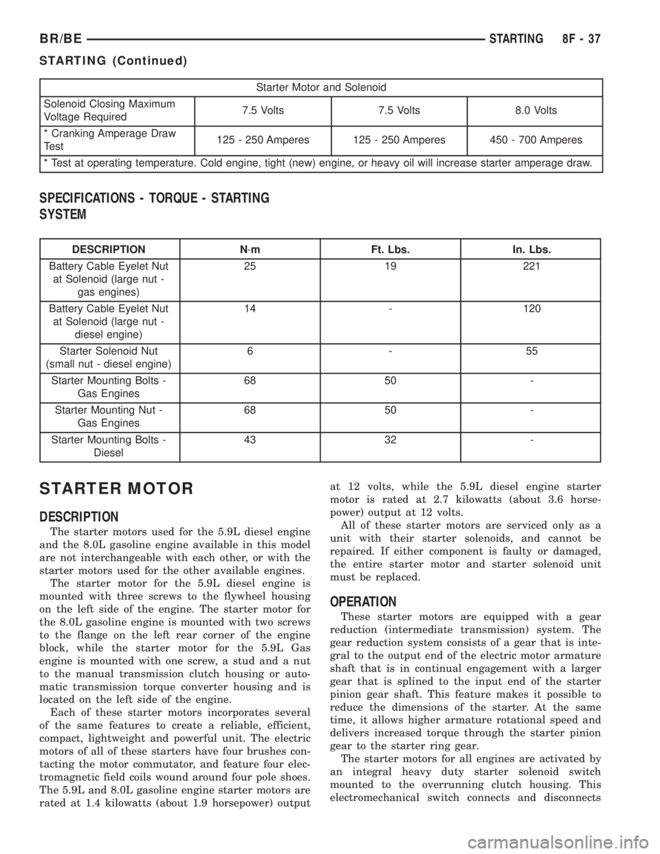
Starter Motor and Solenoid
Solenoid Closing Maximum
Voltage Required7.5 Volts 7.5 Volts 8.0 Volts
* Cranking Amperage Draw
Test125 - 250 Amperes 125 - 250 Amperes 450 - 700 Amperes
* Test at operating temperature. Cold engine, tight (new) engine, or heavy oil will increase starter amperage draw.
SPECIFICATIONS - TORQUE - STARTING
SYSTEM
DESCRIPTION N´m Ft. Lbs. In. Lbs.
Battery Cable Eyelet Nut
at Solenoid (large nut -
gas engines)25 19 221
Battery Cable Eyelet Nut
at Solenoid (large nut -
diesel engine)14 - 120
Starter Solenoid Nut
(small nut - diesel engine)6-55
Starter Mounting Bolts -
Gas Engines68 50 -
Starter Mounting Nut -
Gas Engines68 50 -
Starter Mounting Bolts -
Diesel43 32 -
STARTER MOTOR
DESCRIPTION
The starter motors used for the 5.9L diesel engine
and the 8.0L gasoline engine available in this model
are not interchangeable with each other, or with the
starter motors used for the other available engines.
The starter motor for the 5.9L diesel engine is
mounted with three screws to the flywheel housing
on the left side of the engine. The starter motor for
the 8.0L gasoline engine is mounted with two screws
to the flange on the left rear corner of the engine
block, while the starter motor for the 5.9L Gas
engine is mounted with one screw, a stud and a nut
to the manual transmission clutch housing or auto-
matic transmission torque converter housing and is
located on the left side of the engine.
Each of these starter motors incorporates several
of the same features to create a reliable, efficient,
compact, lightweight and powerful unit. The electric
motors of all of these starters have four brushes con-
tacting the motor commutator, and feature four elec-
tromagnetic field coils wound around four pole shoes.
The 5.9L and 8.0L gasoline engine starter motors are
rated at 1.4 kilowatts (about 1.9 horsepower) outputat 12 volts, while the 5.9L diesel engine starter
motor is rated at 2.7 kilowatts (about 3.6 horse-
power) output at 12 volts.
All of these starter motors are serviced only as a
unit with their starter solenoids, and cannot be
repaired. If either component is faulty or damaged,
the entire starter motor and starter solenoid unit
must be replaced.
OPERATION
These starter motors are equipped with a gear
reduction (intermediate transmission) system. The
gear reduction system consists of a gear that is inte-
gral to the output end of the electric motor armature
shaft that is in continual engagement with a larger
gear that is splined to the input end of the starter
pinion gear shaft. This feature makes it possible to
reduce the dimensions of the starter. At the same
time, it allows higher armature rotational speed and
delivers increased torque through the starter pinion
gear to the starter ring gear.
The starter motors for all engines are activated by
an integral heavy duty starter solenoid switch
mounted to the overrunning clutch housing. This
electromechanical switch connects and disconnects
BR/BESTARTING 8F - 37
STARTING (Continued)
Page 430 of 2255
STARTER MOTOR RELAY
DESCRIPTION
The starter relay is an electromechanical device
that switches battery current to the pull-in coil of the
starter solenoid when ignition switch is turned to
Start position. The starter relay is located in the
Power Distribution Center (PDC) in the engine com-
partment. See PDC cover for relay identification and
location.
The starter relay is a International Standards
Organization (ISO) relay. Relays conforming to ISO
specifications have common physical dimensions, cur-
rent capacities, terminal patterns, and terminal func-
tions.
The starter relay cannot be repaired or adjusted
and, if faulty or damaged, it must be replaced.
OPERATION
The ISO relay consists of an electromagnetic coil, a
resistor or diode, and three (two fixed and one mov-
able) electrical contacts. The movable (common feed)
relay contact is held against one of the fixed contacts
(normally closed) by spring pressure. When electro-
magnetic coil is energized, it draws the movable con-
tact away from normally closed fixed contact, and
holds it against the other (normally open) fixed con-
tact.
When electromagnetic coil is de-energized, spring
pressure returns movable contact to normally closed
position. The resistor or diode is connected in parallel
with electromagnetic coil within relay, and helps to
dissipate voltage spikes produced when coil is de-en-
ergized.
DIAGNOSIS AND TESTING - STARTER RELAY
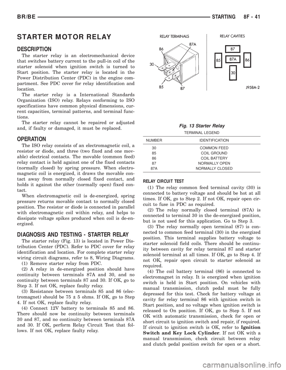
The starter relay (Fig. 13) is located in Power Dis-
tribution Center (PDC). Refer to PDC cover for relay
identification and location. For complete starter relay
wiring circuit diagrams, refer to 8, Wiring Diagrams.
(1) Remove starter relay from PDC.
(2) A relay in de-energized position should have
continuity between terminals 87A and 30, and no
continuity between terminals 87 and 30. If OK, go to
Step 3. If not OK, replace faulty relay.
(3) Resistance between terminals 85 and 86 (elec-
tromagnet) should be 75 5 ohms. If OK, go to Step
4. If not OK, replace faulty relay.
(4) Connect 12V battery to terminals 85 and 86.
There should now be continuity between terminals
30 and 87, and no continuity between terminals 87A
and 30. If OK, perform Relay Circuit Test that fol-
lows. If not OK, replace faulty relay.RELAY CIRCUIT TEST
(1) The relay common feed terminal cavity (30) is
connected to battery voltage and should be hot at all
times. If OK, go to Step 2. If not OK, repair open cir-
cuit to fuse in PDC as required.
(2) The relay normally closed terminal (87A) is
connected to terminal 30 in the de-energized position,
but is not used for this application. Go to Step 3.
(3) The relay normally open terminal (87) is con-
nected to common feed terminal (30) in the energized
position. This terminal supplies battery voltage to
starter solenoid field coils. There should be continu-
ity between cavity for relay terminal 87 and starter
solenoid terminal at all times. If OK, go to Step 4. If
not OK, repair open circuit to starter solenoid as
required.
(4) The coil battery terminal (86) is connected to
electromagnet in relay. It is energized when ignition
switch is held in Start position. On vehicles with
manual transmission, clutch pedal must be fully
depressed for this test. Check for battery voltage at
cavity for relay terminal 86 with ignition switch in
Start position, and no voltage when ignition switch is
released to On position. If OK, go to Step 5. If not
OK with automatic transmission, check for open or
short circuit to ignition switch and repair, if required.
If circuit to ignition switch is OK, refer toIgnition
Switch and Key Lock Cylinder. If not OK with a
manual transmission, check circuit between relay
and clutch pedal position switch for open or a short.
Fig. 13 Starter Relay
TERMINAL LEGEND
NUMBER IDENTIFICATION
30 COMMON FEED
85 COIL GROUND
86 COIL BATTERY
87 NORMALLY OPEN
87A NORMALLY CLOSED
BR/BESTARTING 8F - 41
Page 435 of 2255
harness connector for the heated mirror switch. If
OK, go to Step 5. If not OK, repair the open fused
ignition switch output (run/start) circuit to the fuse
in the JB as required.
(5) Turn the ignition switch to the Off position.
Disconnect and isolate the battery negative cable.
Reconnect the 3-way instrument panel wire harness
connector for the heated mirror switch to the heated
mirror switch connector receptacle on the back of the
a/c heater control. Reconnect the battery negative
cable. Turn the ignition switch to the On position.
Depress and release the heated mirror switch. The
amber heated mirror system indicator lamp next to
the heated mirror switch button should light. If OK,
go to Step 6. If not OK, replace the faulty a/c heater
control.
(6) Back probe the fused heated mirror relay out-
put circuit cavity of the 3-way instrument panel wire
harness connector for the heated mirror switch on
the back of the a/c heater control and check for volt-
age (battery voltage less the resistance in both out-
side mirror heating grids). If OK, (Refer to 8 -
ELECTRICAL/HEATED MIRRORS/HEATED MIR-
ROR GRID - DIAGNOSIS AND TESTING).
HEATED MIRROR GRID
DESCRIPTION
Vehicles equipped with the optional heated mirror
system have an electrically operated heating grid
located behind the mirror glass of each power oper-
ated outside rear view mirror. The outside mirror
heating grid consists of two thin laminations of plas-
tic that approximate the outer dimensions and shape
of the mirror glass. A single length of resistor wire
weaves in a back and forth pattern between, and is
held in place by the two thin laminations of plastic.
The two ends of the resistor wire terminate near the
inboard edge of the grid, where they are soldered to
the ground feed and battery current feed wires con-
tained in the power mirror wire harness. The heating
grid is then sandwiched between the back of the
molded plastic mirror glass case and the mirror
glass, where it remains in direct contact with the
back of the mirror glass at all times.
The outside mirror heating grids cannot be
repaired and, if faulty or damaged, the entire outside
power mirror unit must be replaced. Refer to Power
Mirrors for the service procedures.
OPERATION
One end of the outside mirror heating grid resistor
wire is connected to a ground feed at all times
through a body ground screw located inside the left
rear corner of the truck cab. Battery current is
directed to the other end of the outside mirror heat-
ing grid resistor wire by the energized heated mirror
relay when the heated mirror switch is in the On
position. As electrical current passes through the
heating grid, the resistance of the wire in the heating
grid converts some of that electrical current into
heat. The heat produced by the heating grid is then
conducted through the back of the mirror glass to
help keep the glass clear of ice, snow or fog.
DIAGNOSIS AND TESTING - HEATED MIRROR
GRID
For circuit descriptions and diagrams (Refer to
Appropriate Wiring Information).
(1) Disconnect and isolate the battery negative
cable. Disconnect the door wire harness connector
from the power mirror wire harness connector at the
power mirror with the inoperative heating grid.
Check for continuity between the ground circuit cav-
ity in the door wire harness connector for the power
mirror and a good ground. If OK, go to Step 2. If not
OK, repair the open ground circuit to ground as
required.
(2) Reconnect the battery negative cable. Turn the
ignition switch to the On position. Turn on the
heated mirror system. Check for voltage (battery
voltage less the resistance in the outside mirror heat-
ing grid that is still connected) at the fused heated
mirror relay output circuit cavity in the door wire
harness connector for the power mirror. If OK, go to
Step 3. If not OK, repair the open fused heated mir-
ror relay output circuit to the heater and air condi-
tioner control unit as required.
(3) Check the outside mirror heating grid by test-
ing for continuity between the ground circuit and the
fused heated mirror relay output circuit cavities in
the power mirror wire harness connector. There
should be continuity. If not OK, replace the faulty
power mirror. If OK, check the resistance through
the outside mirror heating grid. The correct resis-
tance should be from 10 to 16 ohms when measured
at an ambient temperature of 21É C (70É F). If not
OK, replace the faulty power mirror.
8G - 4 HEATED MIRRORSBR/BE
MIRROR SWITCH (Continued)
Page 445 of 2255
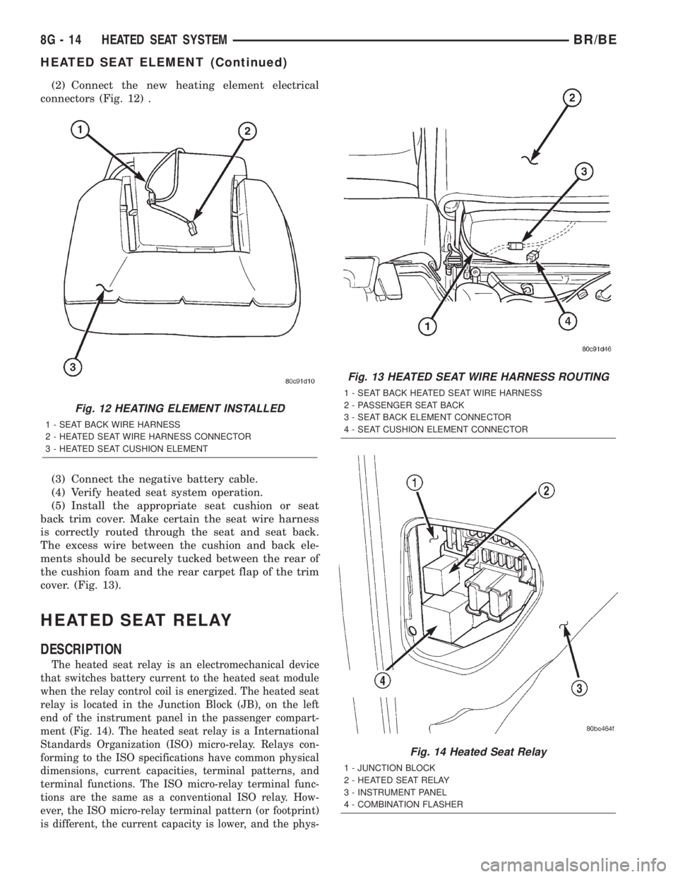
(2) Connect the new heating element electrical
connectors (Fig. 12) .
(3) Connect the negative battery cable.
(4) Verify heated seat system operation.
(5) Install the appropriate seat cushion or seat
back trim cover. Make certain the seat wire harness
is correctly routed through the seat and seat back.
The excess wire between the cushion and back ele-
ments should be securely tucked between the rear of
the cushion foam and the rear carpet flap of the trim
cover. (Fig. 13).
HEATED SEAT RELAY
DESCRIPTION
The heated seat relay is an electromechanical device
that switches battery current to the heated seat module
when the relay control coil is energized. The heated seat
relay is located in the Junction Block (JB), on the left
end of the instrument panel in the passenger compart-
ment (Fig. 14). The heated seat relay is a International
Standards Organization (ISO) micro-relay. Relays con-
forming to the ISO specifications have common physical
dimensions, current capacities, terminal patterns, and
terminal functions. The ISO micro-relay terminal func-
tions are the same as a conventional ISO relay. How-
ever, the ISO micro-relay terminal pattern (or footprint)
is different, the current capacity is lower, and the phys-
Fig. 12 HEATING ELEMENT INSTALLED
1 - SEAT BACK WIRE HARNESS
2 - HEATED SEAT WIRE HARNESS CONNECTOR
3 - HEATED SEAT CUSHION ELEMENT
Fig. 13 HEATED SEAT WIRE HARNESS ROUTING
1 - SEAT BACK HEATED SEAT WIRE HARNESS
2 - PASSENGER SEAT BACK
3 - SEAT BACK ELEMENT CONNECTOR
4 - SEAT CUSHION ELEMENT CONNECTOR
Fig. 14 Heated Seat Relay
1 - JUNCTION BLOCK
2 - HEATED SEAT RELAY
3 - INSTRUMENT PANEL
4 - COMBINATION FLASHER
8G - 14 HEATED SEAT SYSTEMBR/BE
HEATED SEAT ELEMENT (Continued)
Page 446 of 2255
ical dimensions are smaller than those of the conven-
tional ISO relay.
The heated seat relay cannot be repaired or
adjusted and, if faulty or damaged, it must be
replaced.
OPERATION
The ISO relay consists of an electromagnetic coil, a
resistor or diode, and three (two fixed and one mov-
able) electrical contacts. The movable (common feed)
relay contact is held against one of the fixed contacts
(normally closed) by spring pressure. When the elec-
tromagnetic coil is energized, it draws the movable
contact away from the normally closed fixed contact,
and holds it against the other (normally open) fixed
contact. When the electromagnetic coil is de-ener-
gized, spring pressure returns the movable contact to
the normally closed position. The resistor or diode is
connected in parallel with the electromagnetic coil in
the relay, and helps to dissipate voltage spikes that
are produced when the coil is de-energized.
The heated seat relay is controlled by the premium
version of the Central Timer Module (CTM), which
controls the ground feed to the coil ground terminal
of the relay to energize and de-energize the electro-
magnetic coil of the relay. The CTM monitors engine
operation through messages it receives from the Pow-
ertrain Control Module (PCM) over the Chrysler Col-
lision Detection (CCD) data bus network. The CTM is
programmed to energize the relay only when the
engine is running, and to de-energize the relay when
the engine is not running. Refer toCentral Timer
Modulein the index of this service manual for the
location of more information on the premium CTM.
DIAGNOSIS AND TESTING - HEATED SEAT
RELAY
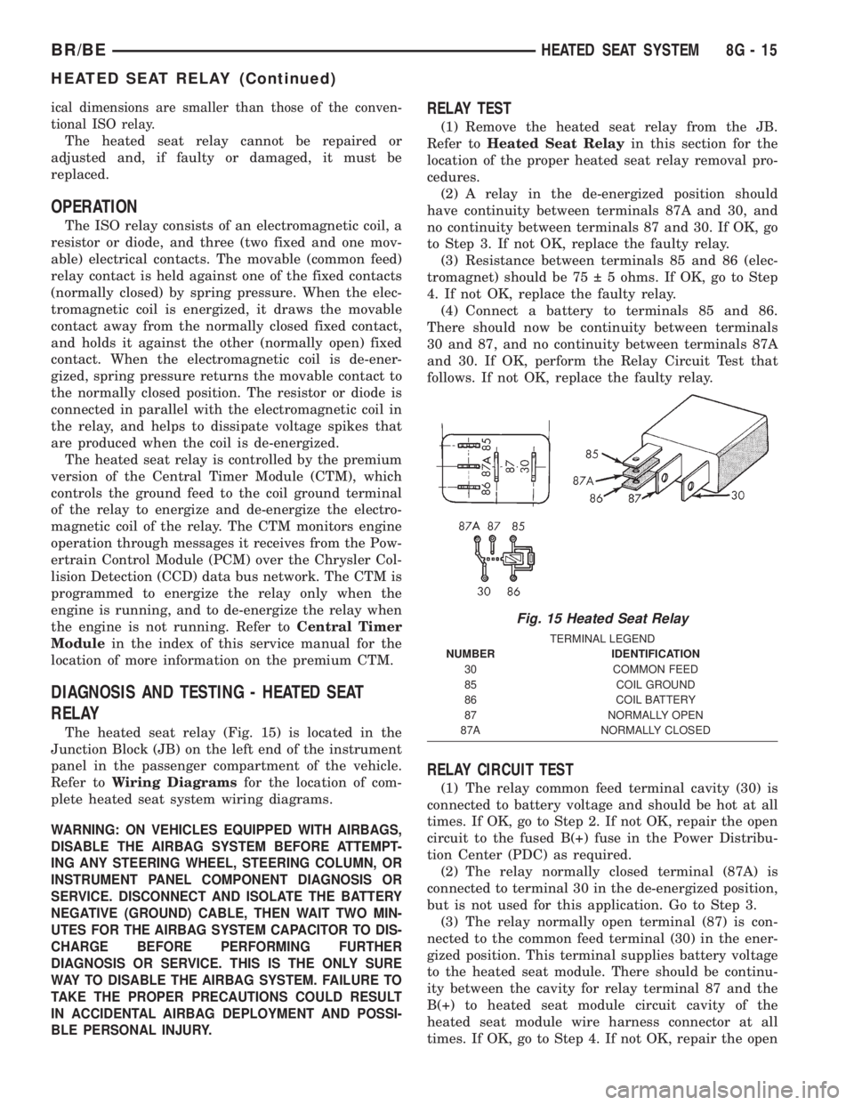
The heated seat relay (Fig. 15) is located in the
Junction Block (JB) on the left end of the instrument
panel in the passenger compartment of the vehicle.
Refer toWiring Diagramsfor the location of com-
plete heated seat system wiring diagrams.
WARNING: ON VEHICLES EQUIPPED WITH AIRBAGS,
DISABLE THE AIRBAG SYSTEM BEFORE ATTEMPT-
ING ANY STEERING WHEEL, STEERING COLUMN, OR
INSTRUMENT PANEL COMPONENT DIAGNOSIS OR
SERVICE. DISCONNECT AND ISOLATE THE BATTERY
NEGATIVE (GROUND) CABLE, THEN WAIT TWO MIN-
UTES FOR THE AIRBAG SYSTEM CAPACITOR TO DIS-
CHARGE BEFORE PERFORMING FURTHER
DIAGNOSIS OR SERVICE. THIS IS THE ONLY SURE
WAY TO DISABLE THE AIRBAG SYSTEM. FAILURE TO
TAKE THE PROPER PRECAUTIONS COULD RESULT
IN ACCIDENTAL AIRBAG DEPLOYMENT AND POSSI-
BLE PERSONAL INJURY.
RELAY TEST
(1) Remove the heated seat relay from the JB.
Refer toHeated Seat Relayin this section for the
location of the proper heated seat relay removal pro-
cedures.
(2) A relay in the de-energized position should
have continuity between terminals 87A and 30, and
no continuity between terminals 87 and 30. If OK, go
to Step 3. If not OK, replace the faulty relay.
(3) Resistance between terminals 85 and 86 (elec-
tromagnet) should be 75 5 ohms. If OK, go to Step
4. If not OK, replace the faulty relay.
(4) Connect a battery to terminals 85 and 86.
There should now be continuity between terminals
30 and 87, and no continuity between terminals 87A
and 30. If OK, perform the Relay Circuit Test that
follows. If not OK, replace the faulty relay.
RELAY CIRCUIT TEST
(1) The relay common feed terminal cavity (30) is
connected to battery voltage and should be hot at all
times. If OK, go to Step 2. If not OK, repair the open
circuit to the fused B(+) fuse in the Power Distribu-
tion Center (PDC) as required.
(2) The relay normally closed terminal (87A) is
connected to terminal 30 in the de-energized position,
but is not used for this application. Go to Step 3.
(3) The relay normally open terminal (87) is con-
nected to the common feed terminal (30) in the ener-
gized position. This terminal supplies battery voltage
to the heated seat module. There should be continu-
ity between the cavity for relay terminal 87 and the
B(+) to heated seat module circuit cavity of the
heated seat module wire harness connector at all
times. If OK, go to Step 4. If not OK, repair the open
Fig. 15 Heated Seat Relay
TERMINAL LEGEND
NUMBER IDENTIFICATION
30 COMMON FEED
85 COIL GROUND
86 COIL BATTERY
87 NORMALLY OPEN
87A NORMALLY CLOSED
BR/BEHEATED SEAT SYSTEM 8G - 15
HEATED SEAT RELAY (Continued)
Page 454 of 2255
INSTALLATION
(1) Position the horn and mounting bracket unit(s)
onto the right fender wheel house front extension.
(2) Install and tighten the screw that secures the
horn and mounting bracket unit(s) to the right
fender wheel house front extension. Tighten the
screw to 11 N´m (95 in. lbs.).
(3) Reconnect the wire harness connector(s) to the
horn connector receptacle(s).
(4) Reconnect the battery negative cable.
HORN RELAY
DESCRIPTION
The horn relay is a electromechanical device that
switches battery current to the horn when the horn
switch grounds the relay coil. The horn relay is
located in the Power Distribution Center (PDC) in
the engine compartment. If a problem is encountered
with a continuously sounding horn, it can usually be
quickly resolved by removing the horn relay from the
PDC until further diagnosis is completed. See the
fuse and relay layout label affixed to the inside sur-
face of the PDC cover for horn relay identification
and location.
The horn relay is a International Standards Orga-
nization (ISO) micro-relay. Relays conforming to the
ISO specifications have common physical dimensions,
current capacities, terminal patterns, and terminal
functions. The ISO micro-relay terminal functions
are the same as a conventional ISO relay. However,
the ISO micro-relay terminal pattern (or footprint) is
different, the current capacity is lower, and the phys-
ical dimensions are smaller than those of the conven-
tional ISO relay.
The horn relay cannot be repaired or adjusted and,
if faulty or damaged, it must be replaced.
OPERATION
The ISO relay consists of an electromagnetic coil, a
resistor or diode, and three (two fixed and one mov-
able) electrical contacts. The movable (common feed)
relay contact is held against one of the fixed contacts
(normally closed) by spring pressure. When the elec-
tromagnetic coil is energized, it draws the movable
contact away from the normally closed fixed contact,
and holds it against the other (normally open) fixed
contact.
When the electromagnetic coil is de-energized,
spring pressure returns the movable contact to the
normally closed position. The resistor or diode is con-
nected in parallel with the electromagnetic coil in the
relay, and helps to dissipate voltage spikes that are
produced when the coil is de-energized.
DIAGNOSIS AND TESTING - HORN RELAY
The horn relay (Fig. 2) is located in the Power Dis-
tribution Center (PDC) behind the battery on the
driver side of the engine compartment. If a problem
is encountered with a continuously sounding horn, it
can usually be quickly resolved by removing the horn
relay from the PDC until further diagnosis is com-
pleted. See the fuse and relay layout label affixed to
the inside surface of the PDC cover for horn relay
identification and location. For complete circuit dia-
grams, refer to the appropriate wiring information.
The wiring information includes wiring diagrams,
proper wire and connector repair procedures, details
of wire harness routing and retention, connector pin-
out information and location views for the various
wire harness connectors, splices and grounds.
WARNING: ON VEHICLES EQUIPPED WITH AIR-
BAGS, REFER TO ELECTRICAL, RESTRAINTS
BEFORE ATTEMPTING ANY STEERING WHEEL,
STEERING COLUMN, OR INSTRUMENT PANEL
COMPONENT DIAGNOSIS OR SERVICE. FAILURE
TO TAKE THE PROPER PRECAUTIONS COULD
RESULT IN ACCIDENTAL AIRBAG DEPLOYMENT
AND POSSIBLE PERSONAL INJURY.
(1) Remove the horn relay from the PDC. (Refer to
8 - ELECTRICAL/HORN/HORN RELAY -
REMOVAL) for the procedures.
(2) A relay in the de-energized position should
have continuity between terminals 87A and 30, and
no continuity between terminals 87 and 30. If OK, go
to Step 3. If not OK, replace the faulty relay.
(3) Resistance between terminals 85 and 86 (elec-
tromagnet) should be 75 5 ohms. If OK, go to Step
4. If not OK, replace the faulty relay.
(4) Connect a battery to terminals 85 and 86.
There should now be continuity between terminals
30 and 87, and no continuity between terminals 87A
and 30. If OK, perform the Relay Circuit Test that
follows. If not OK, replace the faulty relay.
RELAY CIRCUIT TEST
(1) The relay common feed terminal cavity (30) is
connected to battery voltage and should be hot at all
times. If OK, go to Step 2. If not OK, repair the open
circuit to the fuse in the PDC as required.
(2) The relay normally closed terminal (87A) is
connected to terminal 30 in the de-energized position,
but is not used for this application. Go to Step 3.
(3) The relay normally open terminal (87) is con-
nected to the common feed terminal (30) in the ener-
gized position. This terminal supplies battery voltage
to the horn(s). There should be continuity between
the cavity for relay terminal 87 and the horn relay
output circuit cavity of each horn wire harness con-
BR/BEHORN 8H - 3
HORN (Continued)
Page 468 of 2255
(14) Again, install the sensor into the timing case/
cover with a slight rocking action until the sensor is
aligned to scribe line.
(15) Install sensor mounting bolt and tighten to 6
N´m (50 in. lbs.) torque.
(16) Connect engine wiring harness to sensor.
Replacing With a New Sensor
(1) Apply a small amount of engine oil to the sen-
sor o-ring (Fig. 14).
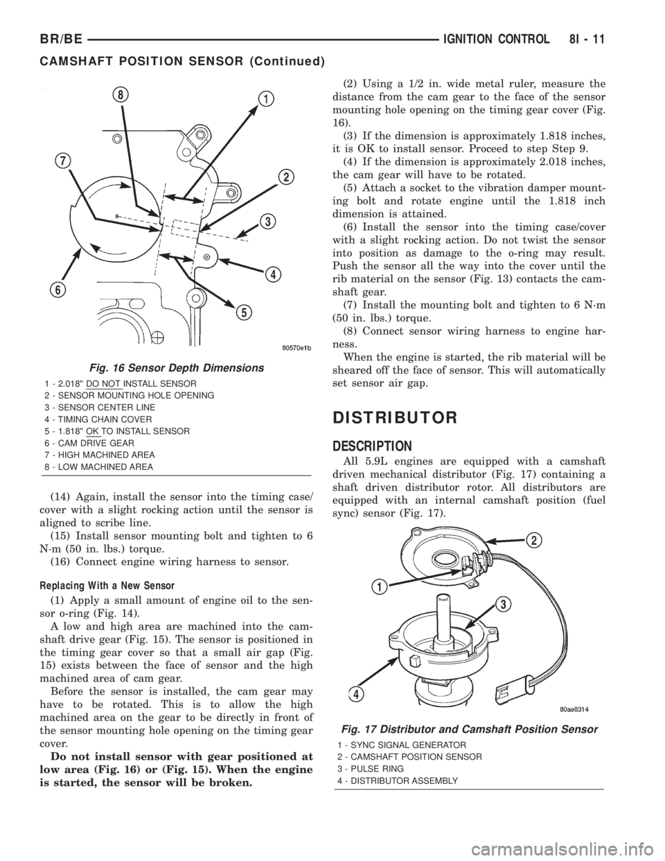
A low and high area are machined into the cam-
shaft drive gear (Fig. 15). The sensor is positioned in
the timing gear cover so that a small air gap (Fig.
15) exists between the face of sensor and the high
machined area of cam gear.
Before the sensor is installed, the cam gear may
have to be rotated. This is to allow the high
machined area on the gear to be directly in front of
the sensor mounting hole opening on the timing gear
cover.
Do not install sensor with gear positioned at
low area (Fig. 16) or (Fig. 15). When the engine
is started, the sensor will be broken.(2) Using a 1/2 in. wide metal ruler, measure the
distance from the cam gear to the face of the sensor
mounting hole opening on the timing gear cover (Fig.
16).
(3) If the dimension is approximately 1.818 inches,
it is OK to install sensor. Proceed to step Step 9.
(4) If the dimension is approximately 2.018 inches,
the cam gear will have to be rotated.
(5) Attach a socket to the vibration damper mount-
ing bolt and rotate engine until the 1.818 inch
dimension is attained.
(6) Install the sensor into the timing case/cover
with a slight rocking action. Do not twist the sensor
into position as damage to the o-ring may result.
Push the sensor all the way into the cover until the
rib material on the sensor (Fig. 13) contacts the cam-
shaft gear.
(7) Install the mounting bolt and tighten to 6 N´m
(50 in. lbs.) torque.
(8) Connect sensor wiring harness to engine har-
ness.
When the engine is started, the rib material will be
sheared off the face of sensor. This will automatically
set sensor air gap.
DISTRIBUTOR
DESCRIPTION
All 5.9L engines are equipped with a camshaft
driven mechanical distributor (Fig. 17) containing a
shaft driven distributor rotor. All distributors are
equipped with an internal camshaft position (fuel
sync) sensor (Fig. 17).
Fig. 16 Sensor Depth Dimensions
1 - 2.018©© DO NOT INSTALL SENSOR
2 - SENSOR MOUNTING HOLE OPENING
3 - SENSOR CENTER LINE
4 - TIMING CHAIN COVER
5 - 1.818©© OK TO INSTALL SENSOR
6 - CAM DRIVE GEAR
7 - HIGH MACHINED AREA
8 - LOW MACHINED AREA
Fig. 17 Distributor and Camshaft Position Sensor
1 - SYNC SIGNAL GENERATOR
2 - CAMSHAFT POSITION SENSOR
3 - PULSE RING
4 - DISTRIBUTOR ASSEMBLY
BR/BEIGNITION CONTROL 8I - 11
CAMSHAFT POSITION SENSOR (Continued)
Page 532 of 2255
HEADLAMP RELAY
DESCRIPTION
The headlamp (or security) relay is located in the
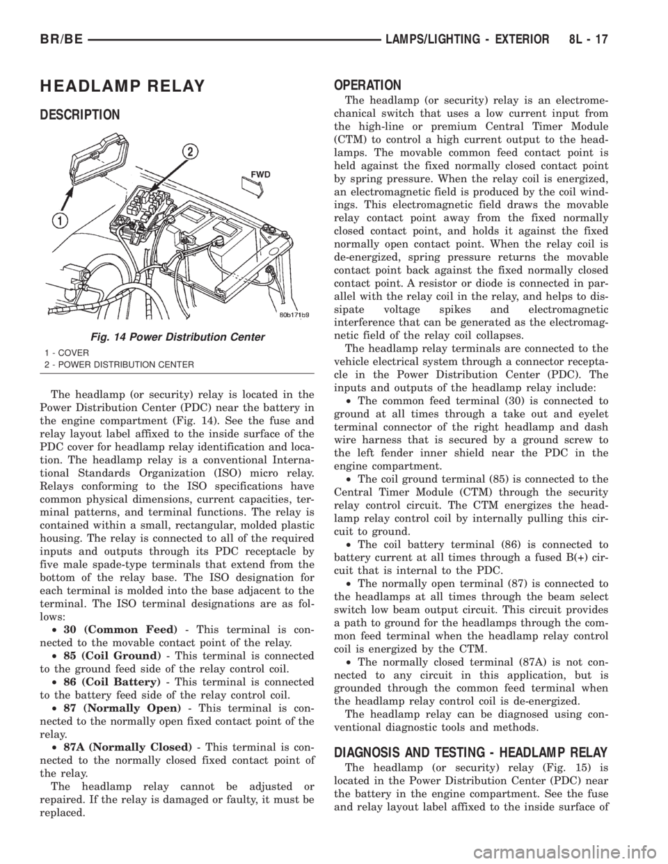
Power Distribution Center (PDC) near the battery in
the engine compartment (Fig. 14). See the fuse and
relay layout label affixed to the inside surface of the
PDC cover for headlamp relay identification and loca-
tion. The headlamp relay is a conventional Interna-
tional Standards Organization (ISO) micro relay.
Relays conforming to the ISO specifications have
common physical dimensions, current capacities, ter-
minal patterns, and terminal functions. The relay is
contained within a small, rectangular, molded plastic
housing. The relay is connected to all of the required
inputs and outputs through its PDC receptacle by
five male spade-type terminals that extend from the
bottom of the relay base. The ISO designation for
each terminal is molded into the base adjacent to the
terminal. The ISO terminal designations are as fol-
lows:
²30 (Common Feed)- This terminal is con-
nected to the movable contact point of the relay.
²85 (Coil Ground)- This terminal is connected
to the ground feed side of the relay control coil.
²86 (Coil Battery)- This terminal is connected
to the battery feed side of the relay control coil.
²87 (Normally Open)- This terminal is con-
nected to the normally open fixed contact point of the
relay.
²87A (Normally Closed)- This terminal is con-
nected to the normally closed fixed contact point of
the relay.
The headlamp relay cannot be adjusted or
repaired. If the relay is damaged or faulty, it must be
replaced.
OPERATION
The headlamp (or security) relay is an electrome-
chanical switch that uses a low current input from
the high-line or premium Central Timer Module
(CTM) to control a high current output to the head-
lamps. The movable common feed contact point is
held against the fixed normally closed contact point
by spring pressure. When the relay coil is energized,
an electromagnetic field is produced by the coil wind-
ings. This electromagnetic field draws the movable
relay contact point away from the fixed normally
closed contact point, and holds it against the fixed
normally open contact point. When the relay coil is
de-energized, spring pressure returns the movable
contact point back against the fixed normally closed
contact point. A resistor or diode is connected in par-
allel with the relay coil in the relay, and helps to dis-
sipate voltage spikes and electromagnetic
interference that can be generated as the electromag-
netic field of the relay coil collapses.
The headlamp relay terminals are connected to the
vehicle electrical system through a connector recepta-
cle in the Power Distribution Center (PDC). The
inputs and outputs of the headlamp relay include:
²The common feed terminal (30) is connected to
ground at all times through a take out and eyelet
terminal connector of the right headlamp and dash
wire harness that is secured by a ground screw to
the left fender inner shield near the PDC in the
engine compartment.
²The coil ground terminal (85) is connected to the
Central Timer Module (CTM) through the security
relay control circuit. The CTM energizes the head-
lamp relay control coil by internally pulling this cir-
cuit to ground.
²The coil battery terminal (86) is connected to
battery current at all times through a fused B(+) cir-
cuit that is internal to the PDC.
²The normally open terminal (87) is connected to
the headlamps at all times through the beam select
switch low beam output circuit. This circuit provides
a path to ground for the headlamps through the com-
mon feed terminal when the headlamp relay control
coil is energized by the CTM.
²The normally closed terminal (87A) is not con-
nected to any circuit in this application, but is
grounded through the common feed terminal when
the headlamp relay control coil is de-energized.
The headlamp relay can be diagnosed using con-
ventional diagnostic tools and methods.
DIAGNOSIS AND TESTING - HEADLAMP RELAY
The headlamp (or security) relay (Fig. 15) is
located in the Power Distribution Center (PDC) near
the battery in the engine compartment. See the fuse
and relay layout label affixed to the inside surface of
Fig. 14 Power Distribution Center
1 - COVER
2 - POWER DISTRIBUTION CENTER
BR/BELAMPS/LIGHTING - EXTERIOR 8L - 17
Page 658 of 2255
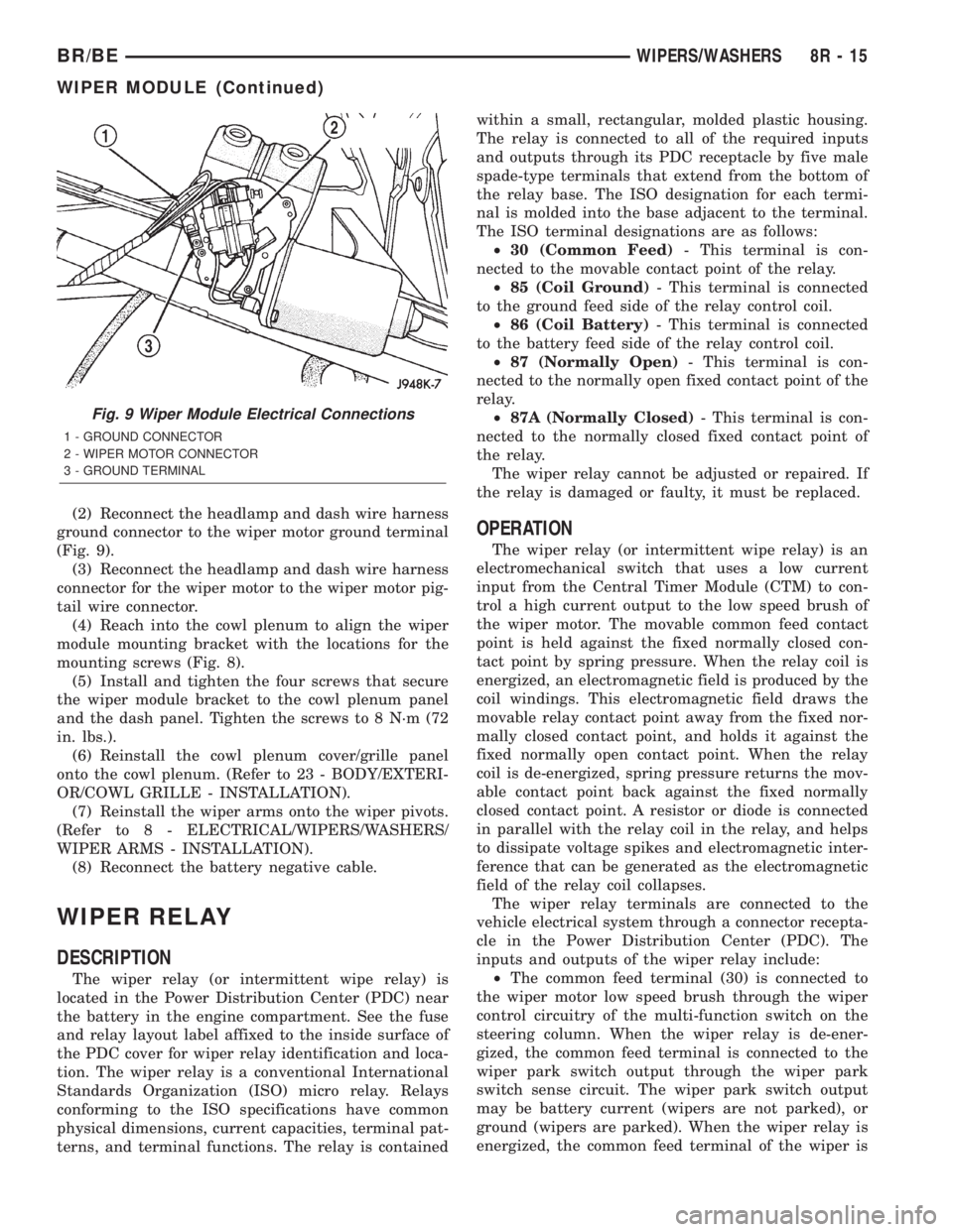
(2) Reconnect the headlamp and dash wire harness
ground connector to the wiper motor ground terminal
(Fig. 9).
(3) Reconnect the headlamp and dash wire harness
connector for the wiper motor to the wiper motor pig-
tail wire connector.
(4) Reach into the cowl plenum to align the wiper
module mounting bracket with the locations for the
mounting screws (Fig. 8).
(5) Install and tighten the four screws that secure
the wiper module bracket to the cowl plenum panel
and the dash panel. Tighten the screws to 8 N´m (72
in. lbs.).
(6) Reinstall the cowl plenum cover/grille panel
onto the cowl plenum. (Refer to 23 - BODY/EXTERI-
OR/COWL GRILLE - INSTALLATION).
(7) Reinstall the wiper arms onto the wiper pivots.
(Refer to 8 - ELECTRICAL/WIPERS/WASHERS/
WIPER ARMS - INSTALLATION).
(8) Reconnect the battery negative cable.
WIPER RELAY
DESCRIPTION
The wiper relay (or intermittent wipe relay) is
located in the Power Distribution Center (PDC) near
the battery in the engine compartment. See the fuse
and relay layout label affixed to the inside surface of
the PDC cover for wiper relay identification and loca-
tion. The wiper relay is a conventional International
Standards Organization (ISO) micro relay. Relays
conforming to the ISO specifications have common
physical dimensions, current capacities, terminal pat-
terns, and terminal functions. The relay is containedwithin a small, rectangular, molded plastic housing.
The relay is connected to all of the required inputs
and outputs through its PDC receptacle by five male
spade-type terminals that extend from the bottom of
the relay base. The ISO designation for each termi-
nal is molded into the base adjacent to the terminal.
The ISO terminal designations are as follows:
²30 (Common Feed)- This terminal is con-
nected to the movable contact point of the relay.
²85 (Coil Ground)- This terminal is connected
to the ground feed side of the relay control coil.
²86 (Coil Battery)- This terminal is connected
to the battery feed side of the relay control coil.
²87 (Normally Open)- This terminal is con-
nected to the normally open fixed contact point of the
relay.
²87A (Normally Closed)- This terminal is con-
nected to the normally closed fixed contact point of
the relay.
The wiper relay cannot be adjusted or repaired. If
the relay is damaged or faulty, it must be replaced.
OPERATION
The wiper relay (or intermittent wipe relay) is an
electromechanical switch that uses a low current
input from the Central Timer Module (CTM) to con-
trol a high current output to the low speed brush of
the wiper motor. The movable common feed contact
point is held against the fixed normally closed con-
tact point by spring pressure. When the relay coil is
energized, an electromagnetic field is produced by the
coil windings. This electromagnetic field draws the
movable relay contact point away from the fixed nor-
mally closed contact point, and holds it against the
fixed normally open contact point. When the relay
coil is de-energized, spring pressure returns the mov-
able contact point back against the fixed normally
closed contact point. A resistor or diode is connected
in parallel with the relay coil in the relay, and helps
to dissipate voltage spikes and electromagnetic inter-
ference that can be generated as the electromagnetic
field of the relay coil collapses.
The wiper relay terminals are connected to the
vehicle electrical system through a connector recepta-
cle in the Power Distribution Center (PDC). The
inputs and outputs of the wiper relay include:
²The common feed terminal (30) is connected to
the wiper motor low speed brush through the wiper
control circuitry of the multi-function switch on the
steering column. When the wiper relay is de-ener-
gized, the common feed terminal is connected to the
wiper park switch output through the wiper park
switch sense circuit. The wiper park switch output
may be battery current (wipers are not parked), or
ground (wipers are parked). When the wiper relay is
energized, the common feed terminal of the wiper is
Fig. 9 Wiper Module Electrical Connections
1 - GROUND CONNECTOR
2 - WIPER MOTOR CONNECTOR
3 - GROUND TERMINAL
BR/BEWIPERS/WASHERS 8R - 15
WIPER MODULE (Continued)
Page 1071 of 2255
(4) Press firmly on the cigar lighter or power out-
let receptacle base until the retaining bosses of the
mount are fully engaged in their receptacles.
(5) Install the cigar lighter knob and element into
the cigar lighter receptacle base, or the protective cap
into the power outlet receptacle base.
(6) Reconnect the battery negative cable.
HORN RELAY
DESCRIPTION
The horn relay is a International Standards Orga-
nization (ISO) micro-relay. The terminal designations
and functions are the same as a conventional ISO
relay. However, the micro-relay terminal orientation
(or footprint) is different, current capacity is lower,
and the relay case dimensions are smaller than those
of the conventional ISO relay.
The horn relay is a electromechanical device that
switches battery current to the horn when the horn
switch or when the high-line or premium Central
Timer Module (CTM) grounds the relay coil. See
Horn Relay in the Diagnosis and Testing section of
this group for more information.
The horn relay is located in the Power Distribution
Center (PDC), in the engine compartment. Refer to
the PDC label for relay identification and location.
If a problem is encountered with a continuously
sounding horn, it can usually be quickly resolved by
removing the horn relay from the PDC until further
diagnosis is completed.
The horn relay cannot be repaired and, if faulty or
damaged, it must be replaced.
DIAGNOSIS AND TESTING - HORN RELAY
The headlamp (or security) relay and the horn
relay are located in the Power Distribution Center
(PDC) in the engine compartment. Each of these
relays can be tested as described in the following pro-
cedure, however the circuits they are used in do vary.
To test the relay circuits, refer to the circuit descrip-
tions and diagrams in Wiring Diagrams.
WARNING: ON VEHICLES EQUIPPED WITH AIR-
BAGS, REFER TO THE RESTRAINTS SECTION OF
THE SERVICE MANUAL BEFORE ATTEMPTING ANY
STEERING WHEEL, STEERING COLUMN, OR
INSTRUMENT PANEL COMPONENT DIAGNOSIS OR
SERVICE. FAILURE TO TAKE THE PROPER PRE-
CAUTIONS COULD RESULT IN ACCIDENTAL AIR-
BAG DEPLOYMENT AND POSSIBLE PERSONAL
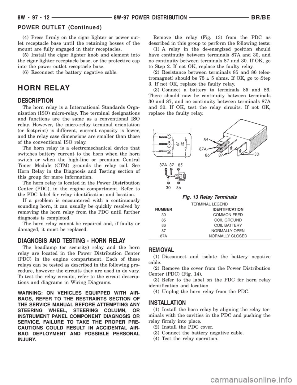
INJURY.Remove the relay (Fig. 13) from the PDC as
described in this group to perform the following tests:
(1) A relay in the de-energized position should
have continuity between terminals 87A and 30, and
no continuity between terminals 87 and 30. If OK, go
to Step 2. If not OK, replace the faulty relay.
(2) Resistance between terminals 85 and 86 (elec-
tromagnet) should be 75 5 ohms. If OK, go to Step
3. If not OK, replace the faulty relay.
(3) Connect a battery to terminals 85 and 86.
There should now be continuity between terminals
30 and 87, and no continuity between terminals 87A
and 30. If OK, test the relay circuits. If not OK,
replace the faulty relay.REMOVAL
(1) Disconnect and isolate the battery negative
cable.
(2) Remove the cover from the Power Distribution
Center (PDC) (Fig. 14).
(3) Refer to the label on the PDC for horn relay
identification and location.
(4) Unplug the horn relay from the PDC.
INSTALLATION
(1) Install the horn relay by aligning the relay ter-
minals with the cavities in the PDC and pushing the
relay firmly into place.
(2) Install the PDC cover.
(3) Connect the battery negative cable.
(4) Test the relay operation.
Fig. 13 Relay Terminals
TERMINAL LEGEND
NUMBER IDENTIFICATION
30 COMMON FEED
85 COIL GROUND
86 COIL BATTERY
87 NORMALLY OPEN
87A NORMALLY CLOSED
8W - 97 - 12 8W-97 POWER DISTRIBUTIONBR/BE
POWER OUTLET (Continued)