fuse diagram DODGE RAM 2002 Service Owner's Manual
[x] Cancel search | Manufacturer: DODGE, Model Year: 2002, Model line: RAM, Model: DODGE RAM 2002Pages: 2255, PDF Size: 62.07 MB
Page 529 of 2255
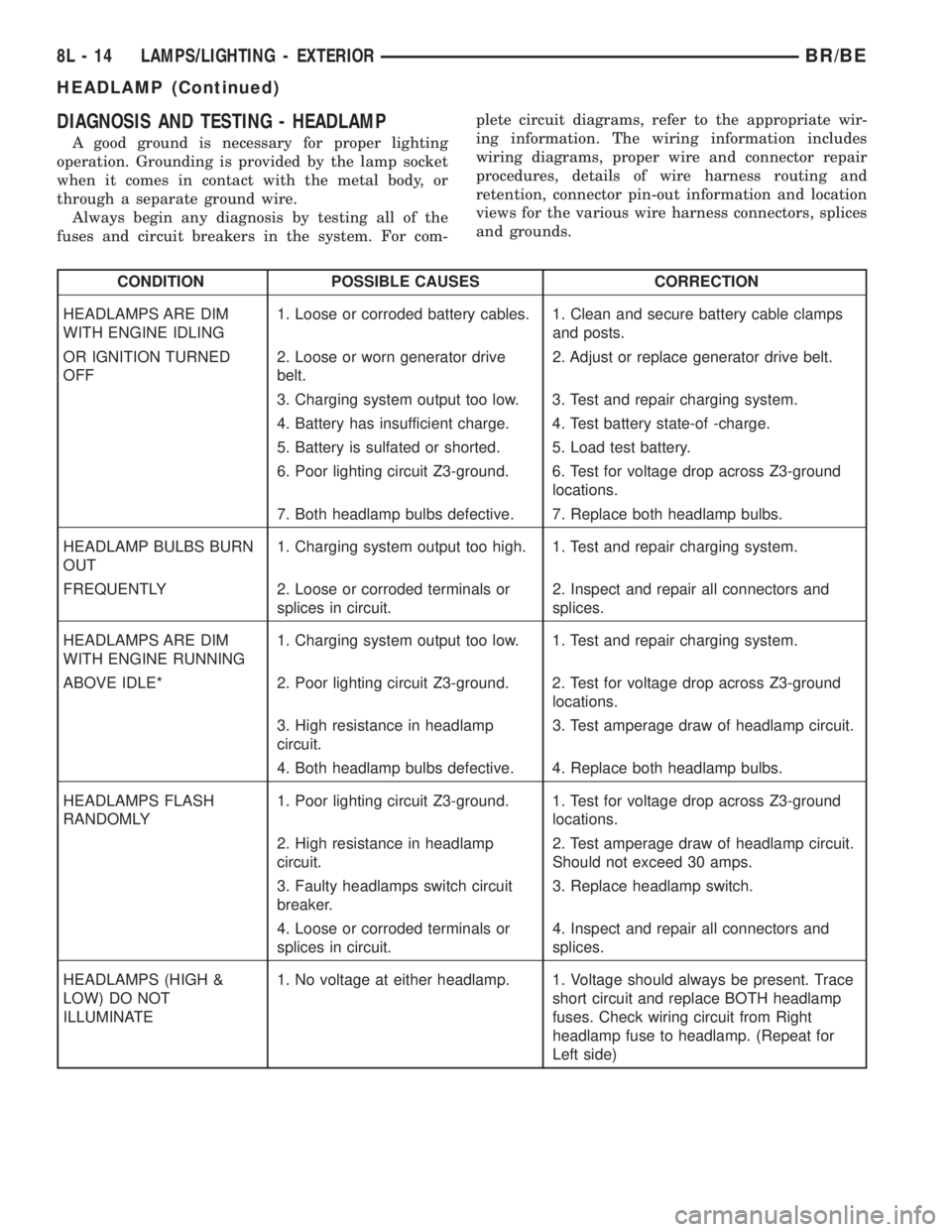
DIAGNOSIS AND TESTING - HEADLAMP
A good ground is necessary for proper lighting
operation. Grounding is provided by the lamp socket
when it comes in contact with the metal body, or
through a separate ground wire.
Always begin any diagnosis by testing all of the
fuses and circuit breakers in the system. For com-plete circuit diagrams, refer to the appropriate wir-
ing information. The wiring information includes
wiring diagrams, proper wire and connector repair
procedures, details of wire harness routing and
retention, connector pin-out information and location
views for the various wire harness connectors, splices
and grounds.
CONDITION POSSIBLE CAUSES CORRECTION
HEADLAMPS ARE DIM
WITH ENGINE IDLING1. Loose or corroded battery cables. 1. Clean and secure battery cable clamps
and posts.
OR IGNITION TURNED
OFF2. Loose or worn generator drive
belt.2. Adjust or replace generator drive belt.
3. Charging system output too low. 3. Test and repair charging system.
4. Battery has insufficient charge. 4. Test battery state-of -charge.
5. Battery is sulfated or shorted. 5. Load test battery.
6. Poor lighting circuit Z3-ground. 6. Test for voltage drop across Z3-ground
locations.
7. Both headlamp bulbs defective. 7. Replace both headlamp bulbs.
HEADLAMP BULBS BURN
OUT1. Charging system output too high. 1. Test and repair charging system.
FREQUENTLY 2. Loose or corroded terminals or
splices in circuit.2. Inspect and repair all connectors and
splices.
HEADLAMPS ARE DIM
WITH ENGINE RUNNING1. Charging system output too low. 1. Test and repair charging system.
ABOVE IDLE* 2. Poor lighting circuit Z3-ground. 2. Test for voltage drop across Z3-ground
locations.
3. High resistance in headlamp
circuit.3. Test amperage draw of headlamp circuit.
4. Both headlamp bulbs defective. 4. Replace both headlamp bulbs.
HEADLAMPS FLASH
RANDOMLY1. Poor lighting circuit Z3-ground. 1. Test for voltage drop across Z3-ground
locations.
2. High resistance in headlamp
circuit.2. Test amperage draw of headlamp circuit.
Should not exceed 30 amps.
3. Faulty headlamps switch circuit
breaker.3. Replace headlamp switch.
4. Loose or corroded terminals or
splices in circuit.4. Inspect and repair all connectors and
splices.
HEADLAMPS (HIGH &
LOW) DO NOT
ILLUMINATE1. No voltage at either headlamp. 1. Voltage should always be present. Trace
short circuit and replace BOTH headlamp
fuses. Check wiring circuit from Right
headlamp fuse to headlamp. (Repeat for
Left side)
8L - 14 LAMPS/LIGHTING - EXTERIORBR/BE
HEADLAMP (Continued)
Page 533 of 2255
the PDC cover for headlamp relay identification and
location. Refer to the appropriate wiring information.
The wiring information includes wiring diagrams,
proper wire and connector repair procedures, details
of wire harness routing and retention, connector pin-
out information and location views for the various
wire harness connectors, splices and grounds.
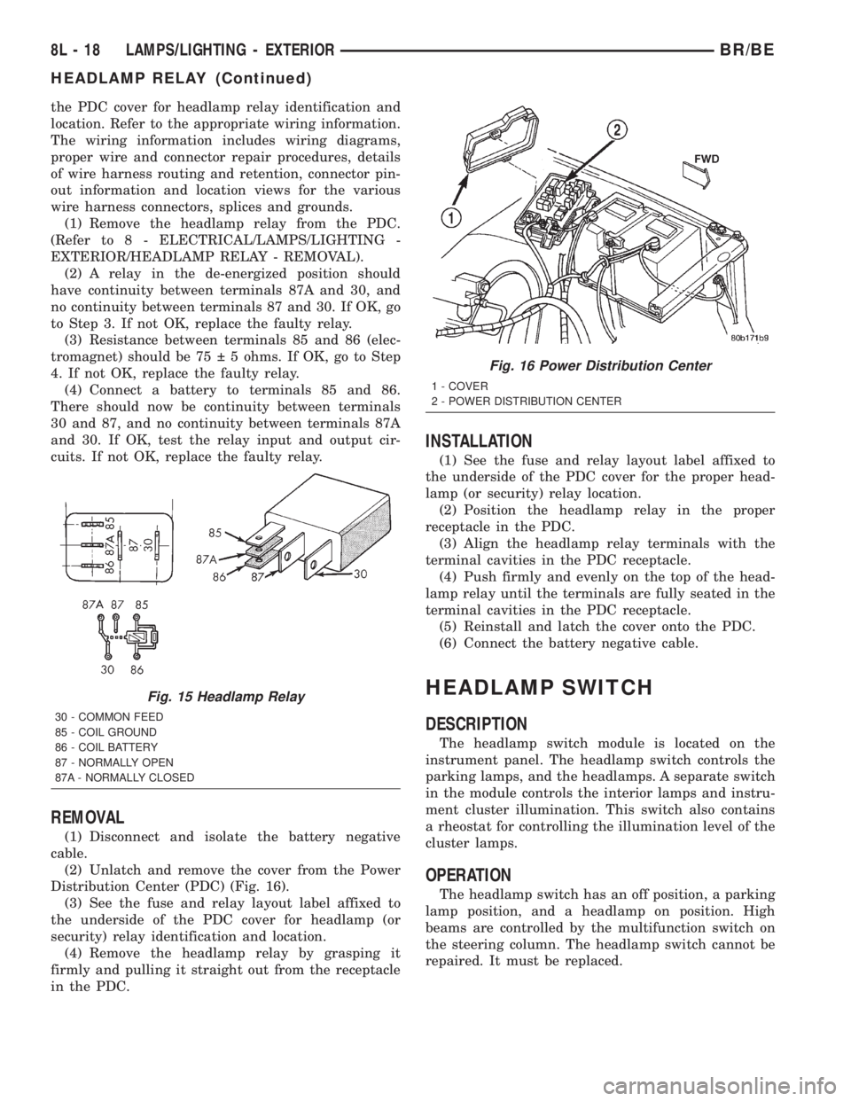
(1) Remove the headlamp relay from the PDC.
(Refer to 8 - ELECTRICAL/LAMPS/LIGHTING -
EXTERIOR/HEADLAMP RELAY - REMOVAL).
(2) A relay in the de-energized position should
have continuity between terminals 87A and 30, and
no continuity between terminals 87 and 30. If OK, go
to Step 3. If not OK, replace the faulty relay.
(3) Resistance between terminals 85 and 86 (elec-
tromagnet) should be 75 5 ohms. If OK, go to Step
4. If not OK, replace the faulty relay.
(4) Connect a battery to terminals 85 and 86.
There should now be continuity between terminals
30 and 87, and no continuity between terminals 87A
and 30. If OK, test the relay input and output cir-
cuits. If not OK, replace the faulty relay.
REMOVAL
(1) Disconnect and isolate the battery negative
cable.
(2) Unlatch and remove the cover from the Power
Distribution Center (PDC) (Fig. 16).
(3) See the fuse and relay layout label affixed to
the underside of the PDC cover for headlamp (or
security) relay identification and location.
(4) Remove the headlamp relay by grasping it
firmly and pulling it straight out from the receptacle
in the PDC.
INSTALLATION
(1) See the fuse and relay layout label affixed to
the underside of the PDC cover for the proper head-
lamp (or security) relay location.
(2) Position the headlamp relay in the proper
receptacle in the PDC.
(3) Align the headlamp relay terminals with the
terminal cavities in the PDC receptacle.
(4) Push firmly and evenly on the top of the head-
lamp relay until the terminals are fully seated in the
terminal cavities in the PDC receptacle.
(5) Reinstall and latch the cover onto the PDC.
(6) Connect the battery negative cable.
HEADLAMP SWITCH
DESCRIPTION
The headlamp switch module is located on the
instrument panel. The headlamp switch controls the
parking lamps, and the headlamps. A separate switch
in the module controls the interior lamps and instru-
ment cluster illumination. This switch also contains
a rheostat for controlling the illumination level of the
cluster lamps.
OPERATION
The headlamp switch has an off position, a parking
lamp position, and a headlamp on position. High
beams are controlled by the multifunction switch on
the steering column. The headlamp switch cannot be
repaired. It must be replaced.
Fig. 15 Headlamp Relay
30 - COMMON FEED
85 - COIL GROUND
86 - COIL BATTERY
87 - NORMALLY OPEN
87A - NORMALLY CLOSED
Fig. 16 Power Distribution Center
1 - COVER
2 - POWER DISTRIBUTION CENTER
8L - 18 LAMPS/LIGHTING - EXTERIORBR/BE
HEADLAMP RELAY (Continued)
Page 563 of 2255
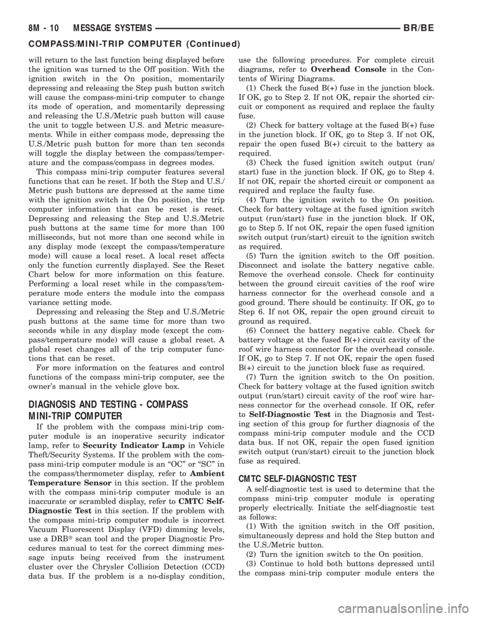
will return to the last function being displayed before
the ignition was turned to the Off position. With the
ignition switch in the On position, momentarily
depressing and releasing the Step push button switch
will cause the compass-mini-trip computer to change
its mode of operation, and momentarily depressing
and releasing the U.S./Metric push button will cause
the unit to toggle between U.S. and Metric measure-
ments. While in either compass mode, depressing the
U.S./Metric push button for more than ten seconds
will toggle the display between the compass/temper-
ature and the compass/compass in degrees modes.
This compass mini-trip computer features several
functions that can be reset. If both the Step and U.S./
Metric push buttons are depressed at the same time
with the ignition switch in the On position, the trip
computer information that can be reset is reset.
Depressing and releasing the Step and U.S./Metric
push buttons at the same time for more than 100
milliseconds, but not more than one second while in
any display mode (except the compass/temperature
mode) will cause a local reset. A local reset affects
only the function currently displayed. See the Reset
Chart below for more information on this feature.
Performing a local reset while in the compass/tem-
perature mode enters the module into the compass
variance setting mode.
Depressing and releasing the Step and U.S./Metric
push buttons at the same time for more than two
seconds while in any display mode (except the com-
pass/temperature mode) will cause a global reset. A
global reset changes all of the trip computer func-
tions that can be reset.
For more information on the features and control
functions of the compass mini-trip computer, see the
owner's manual in the vehicle glove box.
DIAGNOSIS AND TESTING - COMPASS
MINI-TRIP COMPUTER
If the problem with the compass mini-trip com-
puter module is an inoperative security indicator
lamp, refer toSecurity Indicator Lampin Vehicle
Theft/Security Systems. If the problem with the com-
pass mini-trip computer module is an ªOCº or ªSCº in
the compass/thermometer display, refer toAmbient
Temperature Sensorin this section. If the problem
with the compass mini-trip computer module is an
inaccurate or scrambled display, refer toCMTC Self-
Diagnostic Testin this section. If the problem with
the compass mini-trip computer module is incorrect
Vacuum Fluorescent Display (VFD) dimming levels,
use a DRBtscan tool and the proper Diagnostic Pro-
cedures manual to test for the correct dimming mes-
sage inputs being received from the instrument
cluster over the Chrysler Collision Detection (CCD)
data bus. If the problem is a no-display condition,use the following procedures. For complete circuit
diagrams, refer toOverhead Consolein the Con-
tents of Wiring Diagrams.
(1) Check the fused B(+) fuse in the junction block.
If OK, go to Step 2. If not OK, repair the shorted cir-
cuit or component as required and replace the faulty
fuse.
(2) Check for battery voltage at the fused B(+) fuse
in the junction block. If OK, go to Step 3. If not OK,
repair the open fused B(+) circuit to the battery as
required.
(3) Check the fused ignition switch output (run/
start) fuse in the junction block. If OK, go to Step 4.
If not OK, repair the shorted circuit or component as
required and replace the faulty fuse.
(4) Turn the ignition switch to the On position.
Check for battery voltage at the fused ignition switch
output (run/start) fuse in the junction block. If OK,
go to Step 5. If not OK, repair the open fused ignition
switch output (run/start) circuit to the ignition switch
as required.
(5) Turn the ignition switch to the Off position.
Disconnect and isolate the battery negative cable.
Remove the overhead console. Check for continuity
between the ground circuit cavities of the roof wire
harness connector for the overhead console and a
good ground. There should be continuity. If OK, go to
Step 6. If not OK, repair the open ground circuit to
ground as required.
(6) Connect the battery negative cable. Check for
battery voltage at the fused B(+) circuit cavity of the
roof wire harness connector for the overhead console.
If OK, go to Step 7. If not OK, repair the open fused
B(+) circuit to the junction block fuse as required.
(7) Turn the ignition switch to the On position.
Check for battery voltage at the fused ignition switch
output (run/start) circuit cavity of the roof wire har-
ness connector for the overhead console. If OK, refer
toSelf-Diagnostic Testin the Diagnosis and Test-
ing section of this group for further diagnosis of the
compass mini-trip computer module and the CCD
data bus. If not OK, repair the open fused ignition
switch output (run/start) circuit to the junction block
fuse as required.
CMTC SELF-DIAGNOSTIC TEST
A self-diagnostic test is used to determine that the
compass mini-trip computer module is operating
properly electrically. Initiate the self-diagnostic test
as follows:
(1) With the ignition switch in the Off position,
simultaneously depress and hold the Step button and
the U.S./Metric button.
(2) Turn the ignition switch to the On position.
(3) Continue to hold both buttons depressed until
the compass mini-trip computer module enters the
8M - 10 MESSAGE SYSTEMSBR/BE
COMPASS/MINI-TRIP COMPUTER (Continued)
Page 571 of 2255
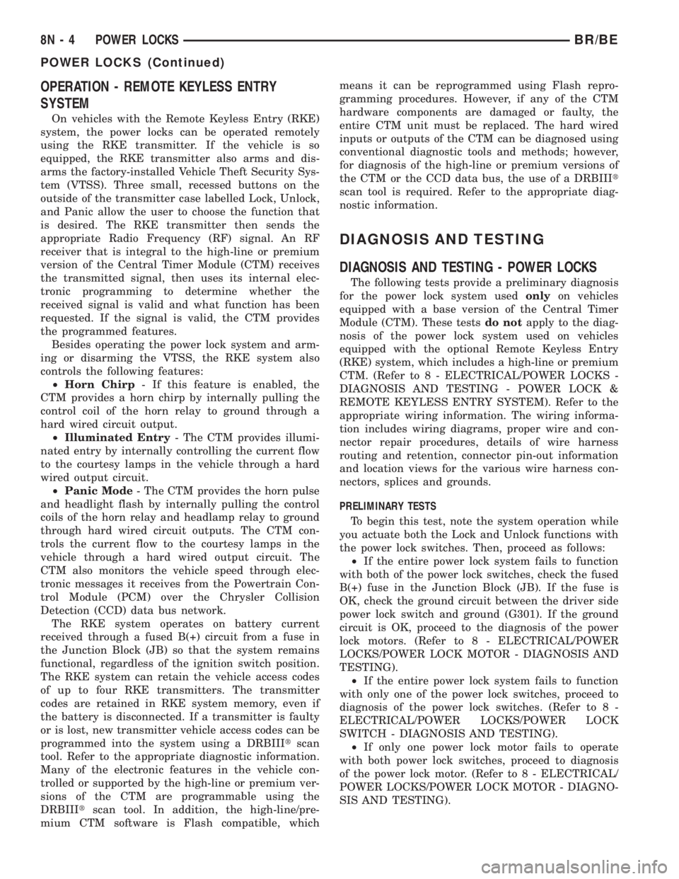
OPERATION - REMOTE KEYLESS ENTRY
SYSTEM
On vehicles with the Remote Keyless Entry (RKE)
system, the power locks can be operated remotely
using the RKE transmitter. If the vehicle is so
equipped, the RKE transmitter also arms and dis-
arms the factory-installed Vehicle Theft Security Sys-
tem (VTSS). Three small, recessed buttons on the
outside of the transmitter case labelled Lock, Unlock,
and Panic allow the user to choose the function that
is desired. The RKE transmitter then sends the
appropriate Radio Frequency (RF) signal. An RF
receiver that is integral to the high-line or premium
version of the Central Timer Module (CTM) receives
the transmitted signal, then uses its internal elec-
tronic programming to determine whether the
received signal is valid and what function has been
requested. If the signal is valid, the CTM provides
the programmed features.
Besides operating the power lock system and arm-
ing or disarming the VTSS, the RKE system also
controls the following features:
²Horn Chirp- If this feature is enabled, the
CTM provides a horn chirp by internally pulling the
control coil of the horn relay to ground through a
hard wired circuit output.
²Illuminated Entry- The CTM provides illumi-
nated entry by internally controlling the current flow
to the courtesy lamps in the vehicle through a hard
wired output circuit.
²Panic Mode- The CTM provides the horn pulse
and headlight flash by internally pulling the control
coils of the horn relay and headlamp relay to ground
through hard wired circuit outputs. The CTM con-
trols the current flow to the courtesy lamps in the
vehicle through a hard wired output circuit. The
CTM also monitors the vehicle speed through elec-
tronic messages it receives from the Powertrain Con-
trol Module (PCM) over the Chrysler Collision
Detection (CCD) data bus network.
The RKE system operates on battery current
received through a fused B(+) circuit from a fuse in
the Junction Block (JB) so that the system remains
functional, regardless of the ignition switch position.
The RKE system can retain the vehicle access codes
of up to four RKE transmitters. The transmitter
codes are retained in RKE system memory, even if
the battery is disconnected. If a transmitter is faulty
or is lost, new transmitter vehicle access codes can be
programmed into the system using a DRBIIItscan
tool. Refer to the appropriate diagnostic information.
Many of the electronic features in the vehicle con-
trolled or supported by the high-line or premium ver-
sions of the CTM are programmable using the
DRBIIItscan tool. In addition, the high-line/pre-
mium CTM software is Flash compatible, whichmeans it can be reprogrammed using Flash repro-
gramming procedures. However, if any of the CTM
hardware components are damaged or faulty, the
entire CTM unit must be replaced. The hard wired
inputs or outputs of the CTM can be diagnosed using
conventional diagnostic tools and methods; however,
for diagnosis of the high-line or premium versions of
the CTM or the CCD data bus, the use of a DRBIIIt
scan tool is required. Refer to the appropriate diag-
nostic information.
DIAGNOSIS AND TESTING
DIAGNOSIS AND TESTING - POWER LOCKS
The following tests provide a preliminary diagnosis
for the power lock system usedonlyon vehicles
equipped with a base version of the Central Timer
Module (CTM). These testsdo notapply to the diag-
nosis of the power lock system used on vehicles
equipped with the optional Remote Keyless Entry
(RKE) system, which includes a high-line or premium
CTM. (Refer to 8 - ELECTRICAL/POWER LOCKS -
DIAGNOSIS AND TESTING - POWER LOCK &
REMOTE KEYLESS ENTRY SYSTEM). Refer to the
appropriate wiring information. The wiring informa-
tion includes wiring diagrams, proper wire and con-
nector repair procedures, details of wire harness
routing and retention, connector pin-out information
and location views for the various wire harness con-
nectors, splices and grounds.
PRELIMINARY TESTS
To begin this test, note the system operation while
you actuate both the Lock and Unlock functions with
the power lock switches. Then, proceed as follows:
²If the entire power lock system fails to function
with both of the power lock switches, check the fused
B(+) fuse in the Junction Block (JB). If the fuse is
OK, check the ground circuit between the driver side
power lock switch and ground (G301). If the ground
circuit is OK, proceed to the diagnosis of the power
lock motors. (Refer to 8 - ELECTRICAL/POWER
LOCKS/POWER LOCK MOTOR - DIAGNOSIS AND
TESTING).
²If the entire power lock system fails to function
with only one of the power lock switches, proceed to
diagnosis of the power lock switches. (Refer to 8 -
ELECTRICAL/POWER LOCKS/POWER LOCK
SWITCH - DIAGNOSIS AND TESTING).
²If only one power lock motor fails to operate
with both power lock switches, proceed to diagnosis
of the power lock motor. (Refer to 8 - ELECTRICAL/
POWER LOCKS/POWER LOCK MOTOR - DIAGNO-
SIS AND TESTING).
8N - 4 POWER LOCKSBR/BE
POWER LOCKS (Continued)
Page 572 of 2255
DIAGNOSIS AND TESTING - POWER LOCK &
REMOTE KEYLESS ENTRY SYSTEM
The following tests include a preliminary diagnosis
for the power lock system usedonlyon vehicles
equipped with the optional Remote Keyless Entry
(RKE) system, which includes a high-line or premium
Central Timer Module (CTM). These testsdo not
apply to the diagnosis of the power lock system on
vehicles equipped with a base version of the CTM.
(Refer to 8 - ELECTRICAL/POWER LOCKS - DIAG-
NOSIS AND TESTING - POWER LOCK SYSTEM).
These tests will help to diagnose the hard wired
components and circuits of the power lock system.
However, these tests may not prove conclusive in the
diagnosis of this system. In order to obtain conclusive
testing of the power lock and RKE system, the
Chrysler Collision Detection (CCD) data bus network
and all of the electronic modules that provide inputs
to, or receive outputs from the power lock and RKE
system components must be checked.
The most reliable, efficient, and accurate means to
diagnose the power lock and RKE system requires
the use of a DRBIIItscan tool. The DRBIIItscan
tool can provide confirmation that the CCD data bus
is functional, that all of the electronic modules are
sending and receiving the proper messages on the
CCD data bus, that the CTM is receiving the proper
hard wired inputs, and that the power lock motors
are being sent the proper hard wired outputs by the
CTM.
Refer to the appropriate wiring information. The
wiring information includes wiring diagrams, proper
wire and connector repair procedures, details of wire
harness routing and retention, connector pin-out
information and location views for the various wire
harness connectors, splices and grounds.
PRELIMINARY TESTS
To begin this test, note the system operation while
you actuate both the Lock and Unlock functions with
the power lock switches, the door cylinder lock
switches, and the RKE transmitter. Then, proceed as
follows:
²If the entire power lock system fails to function
with the power lock switches, the door cylinder lock
switches, or the RKE transmitter, check the fused
B(+) fuse in the Junction Block (JB). If the fuse is
OK, proceed to the diagnosis of the power lock
motors. (Refer to 8 - ELECTRICAL/POWER LOCKS/
POWER LOCK MOTOR - DIAGNOSIS AND TEST-
ING).
²If the power lock system functions with both
power lock switches, and both door cylinder lock
switches, but not with the RKE transmitter, proceed
to the diagnosis of the transmitter. (Refer to 8 -
ELECTRICAL/POWER LOCKS/REMOTE KEYLESSENTRY TRANSMITTER - DIAGNOSIS AND TEST-
ING).
²If the entire power lock system functions with
the RKE transmitter, and both door cylinder lock
switches, but not with one or both of the power lock
switches, proceed to diagnosis of the power lock
switches. (Refer to 8 - ELECTRICAL/POWER
LOCKS/POWER LOCK SWITCH - DIAGNOSIS AND
TESTING).
²If the entire power lock system functions with
the RKE transmitter, and both power lock switches,
but not with one or both of the door cylinder lock
switches, proceed to diagnosis of the door cylinder
lock switches. (Refer to 8 - ELECTRICAL/POWER
LOCKS/DOOR CYLINDER LOCK SWITCH - DIAG-
NOSIS AND TESTING).
²If one power lock motor fails to operate with
both of the power lock switches, both of the door cyl-
inder lock switches and/or the RKE transmitter, pro-
ceed to diagnosis of the power lock motor. (Refer to 8
- ELECTRICAL/POWER LOCKS/POWER LOCK
MOTOR - DIAGNOSIS AND TESTING).
If the problem being diagnosed is related to one or
more of the electronic features (automatic locks, door
lock inhibit, enhanced accident response, illuminated
entry, panic mode, or RKE horn chirp), further diag-
nosis should be performed using a DRBIIItscan tool.
Refer to the appropriate diagnostic information.
DOOR CYLINDER LOCK
SWITCH
DESCRIPTION
A door cylinder lock switch is snapped onto the
back of the key lock cylinder inside each front door of
vehicles equipped with a high-line or premium Cen-
tral Timer Module (CTM). The door cylinder lock
switch is a resistor multiplexed momentary switch
that is hard wired in series between a body ground
and the CTM through the front door wire harness.
The door cylinder lock switches are driven by the key
lock cylinders and contain three internal resistors.
One resistor is used for the neutral switch position,
one for the Lock position, and one for the Unlock
position.
The door cylinder lock switches cannot be adjusted
or repaired and, if faulty or damaged, they must be
replaced.
OPERATION
The door cylinder lock switches are actuated by the
key lock cylinder when the key is inserted in the lock
cylinder and turned to the lock or unlock positions.
The door cylinder lock switch closes a path to ground
through one of three internal resistors for the Cen-
BR/BEPOWER LOCKS 8N - 5
POWER LOCKS (Continued)
Page 576 of 2255
DIAGNOSIS AND TESTING - POWER LOCK
SWITCH
The Light-Emitting Diode (LED) illumination
lamps for all of the power window and lock switch
and bezel unit switch paddles receive battery current
through the power window circuit breaker in the
Junction Block (JB). If all of the LEDs are inopera-
tive in either or both power window and lock switch
and bezel units, be certain to diagnose the power
window system before replacing the switch unit.
(Refer to 8 - ELECTRICAL/POWER WINDOWS -
DIAGNOSIS AND TESTING). If only one LED in a
power window and lock switch and bezel unit is inop-
erative, replace the faulty switch and bezel unit.
Refer to the appropriate wiring information. The wir-
ing information includes wiring diagrams, proper
wire and connector repair procedures, details of wire
harness routing and retention, connector pin-out
information and location views for the various wire
harness connectors, splices and grounds.
(1) Check the fused B(+) fuse (Fuse 13 - 10
ampere) in the Junction Block (JB). If OK, go to Step
2. If not OK, repair the shorted circuit or component
as required and replace the faulty fuse.
(2) Check for battery voltage at the fused B(+) fuse
(Fuse 13 - 10 ampere) in the JB. If OK, go to Step 3.
If not OK, repair the open fused B(+) circuit between
the JB and the Power Distribution Center (PDC) as
required.
(3) Disconnect and isolate the battery negative
cable. Remove the power window and lock switch and
bezel unit from the door trim panel. Disconnect the
door wire harness connector for the power window
and lock switch unit from the switch connector recep-
tacle.
(4) Reconnect the battery negative cable. Check for
battery voltage at the fused B(+) circuit cavity of the
door wire harness connector for the power window
and lock switch unit. If OK, go to Step 5. If not OK,
repair the open fused B(+) circuit between the power
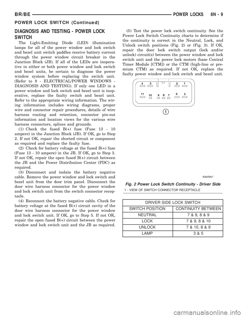
window and lock switch unit and the JB as required.(5) Test the power lock switch continuity. See the
Power Lock Switch Continuity charts to determine if
the continuity is correct in the Neutral, Lock, and
Unlock switch positions (Fig. 2) or (Fig. 3). If OK,
repair the door lock switch output (lock and/or
unlock) circuit(s) between the power window and lock
switch unit and the power lock motors (base Central
Timer Module [CTM]) or the CTM (high-line or pre-
mium CTM) as required. If not OK, replace the
faulty power window and lock switch and bezel unit.
DRIVER SIDE LOCK SWITCH
SWITCH POSITION CONTINUITY BETWEEN
NEUTRAL 7 & 9,8&9
LOCK 7 & 9,8&10
UNLOCK 7 & 10,8&9
LAMP 3 & 5
Fig. 2 Power Lock Switch Continuity - Driver Side
1 - VIEW OF SWITCH CONNECTOR RECEPTACLE
BR/BEPOWER LOCKS 8N - 9
POWER LOCK SWITCH (Continued)
Page 579 of 2255
OPERATION
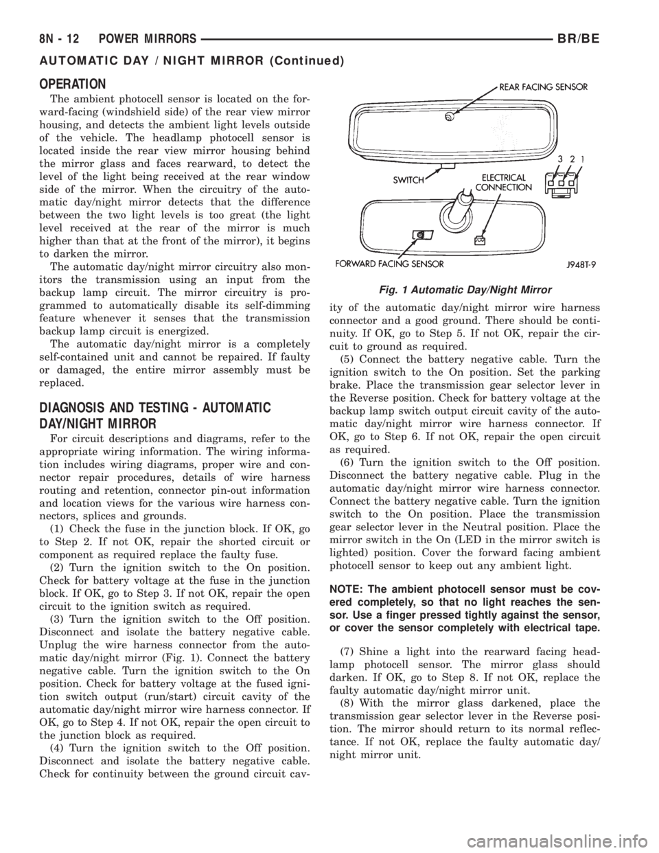
The ambient photocell sensor is located on the for-
ward-facing (windshield side) of the rear view mirror
housing, and detects the ambient light levels outside
of the vehicle. The headlamp photocell sensor is
located inside the rear view mirror housing behind
the mirror glass and faces rearward, to detect the
level of the light being received at the rear window
side of the mirror. When the circuitry of the auto-
matic day/night mirror detects that the difference
between the two light levels is too great (the light
level received at the rear of the mirror is much
higher than that at the front of the mirror), it begins
to darken the mirror.
The automatic day/night mirror circuitry also mon-
itors the transmission using an input from the
backup lamp circuit. The mirror circuitry is pro-
grammed to automatically disable its self-dimming
feature whenever it senses that the transmission
backup lamp circuit is energized.
The automatic day/night mirror is a completely
self-contained unit and cannot be repaired. If faulty
or damaged, the entire mirror assembly must be
replaced.
DIAGNOSIS AND TESTING - AUTOMATIC
DAY/NIGHT MIRROR
For circuit descriptions and diagrams, refer to the
appropriate wiring information. The wiring informa-
tion includes wiring diagrams, proper wire and con-
nector repair procedures, details of wire harness
routing and retention, connector pin-out information
and location views for the various wire harness con-
nectors, splices and grounds.
(1) Check the fuse in the junction block. If OK, go
to Step 2. If not OK, repair the shorted circuit or
component as required replace the faulty fuse.
(2) Turn the ignition switch to the On position.
Check for battery voltage at the fuse in the junction
block. If OK, go to Step 3. If not OK, repair the open
circuit to the ignition switch as required.
(3) Turn the ignition switch to the Off position.
Disconnect and isolate the battery negative cable.
Unplug the wire harness connector from the auto-
matic day/night mirror (Fig. 1). Connect the battery
negative cable. Turn the ignition switch to the On
position. Check for battery voltage at the fused igni-
tion switch output (run/start) circuit cavity of the
automatic day/night mirror wire harness connector. If
OK, go to Step 4. If not OK, repair the open circuit to
the junction block as required.
(4) Turn the ignition switch to the Off position.
Disconnect and isolate the battery negative cable.
Check for continuity between the ground circuit cav-ity of the automatic day/night mirror wire harness
connector and a good ground. There should be conti-
nuity. If OK, go to Step 5. If not OK, repair the cir-
cuit to ground as required.
(5) Connect the battery negative cable. Turn the
ignition switch to the On position. Set the parking
brake. Place the transmission gear selector lever in
the Reverse position. Check for battery voltage at the
backup lamp switch output circuit cavity of the auto-
matic day/night mirror wire harness connector. If
OK, go to Step 6. If not OK, repair the open circuit
as required.
(6) Turn the ignition switch to the Off position.
Disconnect the battery negative cable. Plug in the
automatic day/night mirror wire harness connector.
Connect the battery negative cable. Turn the ignition
switch to the On position. Place the transmission
gear selector lever in the Neutral position. Place the
mirror switch in the On (LED in the mirror switch is
lighted) position. Cover the forward facing ambient
photocell sensor to keep out any ambient light.
NOTE: The ambient photocell sensor must be cov-
ered completely, so that no light reaches the sen-
sor. Use a finger pressed tightly against the sensor,
or cover the sensor completely with electrical tape.
(7) Shine a light into the rearward facing head-
lamp photocell sensor. The mirror glass should
darken. If OK, go to Step 8. If not OK, replace the
faulty automatic day/night mirror unit.
(8) With the mirror glass darkened, place the
transmission gear selector lever in the Reverse posi-
tion. The mirror should return to its normal reflec-
tance. If not OK, replace the faulty automatic day/
night mirror unit.
Fig. 1 Automatic Day/Night Mirror
8N - 12 POWER MIRRORSBR/BE
AUTOMATIC DAY / NIGHT MIRROR (Continued)
Page 581 of 2255
INSTALLATION
(1) Insert the power mirror switch to the back of
the door trim panel.
(2) Connect the power mirror switch to the har-
ness connector.
(3) Install the trim panel to the inside of the
driver side door. (Refer to 23 - BODY/DOOR -
FRONT/TRIM PANEL - INSTALLATION).
(4) Install the nut that secures the power mirror
switch to the driver side front door.
(5) Push the control knob on to the power mirror
switch.
(6) Connect the battery negative cable.
SIDEVIEW MIRROR
DESCRIPTION
Each power mirror head contains two electric
motors, two drive mechanisms, and the mirror glass.
One motor and drive controls mirror up-and-down
movement, and the other controls right-and-left
movement.
OPERATION
The power mirrors in vehicles equipped with the
available heated mirror system option also include an
electric heating grid located behind the mirror glass.
This heating grid is energized by the heated mirror
relay in the heater and air conditioner control only
when the ignition switch is in the On position, and
the heated mirror system is turned on. (Refer to 8 -
ELECTRICAL/HEATED MIRRORS - DESCRIP-
TION) for more information.
The power mirror assembly cannot be repaired. If
any component of the power mirror unit is faulty or
damaged, the entire assembly must be replaced.
DIAGNOSIS AND TESTING - SIDEVIEW
MIRROR
For circuit descriptions and diagrams, refer to the
appropriate wiring information. The wiring informa-
tion includes wiring diagrams, proper wire and con-
nector repair procedures, details of wire harness
routing and retention, connector pin-out information
and location views for the various wire harness con-
nectors, splices and grounds.
(1) Check the fuses in the Power Distribution Cen-
ter (PDC) and the junction block. If OK, go to Step 2.
If not OK, repair the shorted circuit or component as
required and replace the faulty fuse(s).(2) Check for battery voltage at the fuse in the
junction block. If OK, go to Step 3. If not OK, repair
the open circuit to the PDC as required.
(3) Disconnect and isolate the battery negative
cable. Remove the driver side door trim panel and
unplug the wire harness connector from the power
mirror switch. Connect the battery negative cable.
Check for battery voltage at the fused B(+) circuit
cavity in the door wire harness half of the power mir-
ror switch wire harness connector. If OK, go to Step
4. If not OK, repair the open circuit to the junction
block as required.
(4) Disconnect and isolate the battery negative
cable. Check for continuity between the ground cir-
cuit cavity in the door wire harness half of the power
mirror switch wire harness connector and a good
ground. There should be continuity. If OK, go to Step
5. If not OK, repair the circuit to ground as required.
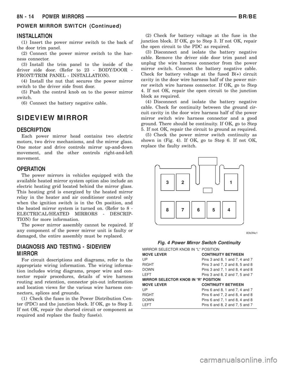
(5) Check the power mirror switch continuity as
shown in (Fig. 4). If OK, go to Step 6. If not OK,
replace the faulty switch.
Fig. 4 Power Mirror Switch Continuity
MIRROR SELECTOR KNOB IN9L9POSITION
MOVE LEVER CONTINUITY BETWEEN
UP Pins 3 and 8, 1 and 7, 4 and 7
RIGHT Pins 3 and 7, 2 and 8, 5 and 8
DOWN Pins 3 and 7, 1 and 8, 4 and 8
LEFT Pins 3 and 8, 2 and 7, 5 and 7
MIRROR SELECTOR KNOB IN(R(POSITION
MOVE LEVER CONTINUITY BETWEEN
UP Pins 6 and 8, 1 and 7, 4 and 7
RIGHT Pins 6 and 7, 2 and 8, 4 and 8
DOWN Pins 6 and 7, 1 and 8, 4 and 8
LEFT Pins 6 and 8, 2 and 7, 5 and 7
8N - 14 POWER MIRRORSBR/BE
POWER MIRROR SWITCH (Continued)
Page 583 of 2255
POWER SEAT SYSTEM
TABLE OF CONTENTS
page page
POWER SEAT SYSTEM
DESCRIPTION.........................16
OPERATION...........................16
DIAGNOSIS AND TESTING - POWER SEAT
SYSTEM............................16
DRIVER POWER SEAT SWITCH
DESCRIPTION.........................17
OPERATION...........................17
DIAGNOSIS AND TESTING - DRIVER POWER
SEAT SWITCH........................17
REMOVAL.............................18
INSTALLATION.........................18
LUMBAR CONTROL SWITCH
DESCRIPTION.........................18
OPERATION...........................19
REMOVAL.............................19
LUMBAR MOTOR
DESCRIPTION.........................19OPERATION...........................19
DIAGNOSIS AND TESTING - LUMBAR MOTOR . 19
PASSENGER POWER SEAT SWITCH
DESCRIPTION.........................20
OPERATION...........................20
DIAGNOSIS AND TESTING - PASSENGER
POWER SEAT SWITCH.................20
REMOVAL.............................21
INSTALLATION.........................21
POWER SEAT TRACK
DESCRIPTION.........................21
OPERATION...........................22
DIAGNOSIS AND TESTING - POWER SEAT
TRACK.............................22
REMOVAL.............................22
INSTALLATION.........................22
POWER SEAT SYSTEM
DESCRIPTION
The power seat system option allows the driver (or
passenger on SLT Plus with power seats) to electri-
cally adjust the seat position for optimum control and
comfort using the power seat switches located on the
outboard seat cushion side shield. The power seat
system allows the seating position to be adjusted for-
ward, rearward, front up, front down, rear up, or
rear down. The power seat system receives battery
current through a fuse in the Power Distribution
Center and a circuit breaker in the junction block,
regardless of the ignition switch position.
The quad cab models equipped with the power seat
option also feature a power operated lumbar support
in the seat back. The power lumbar support allows
the user to inflate or deflate a bladder located in the
lower seat back to achieve optimum comfort and sup-
port in the lower lumbar region of the spinal column.
The power lumbar support shares the battery feed
circuit of the power seat system.
The power seat system includes the power seat
adjuster and motors unit, the power lumbar support
bladder and electric pump (quad cab only), the power
seat switch, and the circuit breaker. Following are
general descriptions of the major components in the
power seat system. Refer toHeated Seat Systemfor information on the individually controlled heated
front seats. Refer to the owner's manual in the vehi-
cle glove box for more information on the features,
use and operation of the power seat system.
OPERATION
The power seat system allows the driver and/or
front passenger seating positions to be adjusted elec-
trically and independently using the separate power
seat switches found on the outboard seat cushion
side shield of each front seat. See the owner's manual
in the vehicle glove box for more information on the
features, use and operation of the power seat system.
DIAGNOSIS AND TESTING - POWER SEAT
SYSTEM
Before any testing of the power seat system is
attempted, the battery should be fully-charged and
all wire harness connections and pins cleaned and
tightened to ensure proper continuity and grounds.
For circuit descriptions and diagrams, refer to Wiring
Diagrams.
With the dome lamp on, apply the power seat
switch in the direction of the failure. If the dome
lamp dims, the seat may be jamming. Check under
and behind the seat for binding or obstructions. If
the dome lamp does not dim, proceed with testing of
the individual components and circuits.
8N - 16 POWER SEAT SYSTEMBR/BE
Page 586 of 2255
OPERATION
When the power lumbar switch paddle is actuated,
a battery feed and a ground path are applied through
the switch contacts to the power lumbar adjuster
motor. The motor operates to move the lumbar
adjuster through its drive unit in the selected direc-
tion until the switch is released, or until the travel
limit of the adjuster is reached. When the switch is
moved in the opposite direction, the battery feed and
ground path to the motor are reversed through the
switch contacts. This causes the motor to run in the
opposite direction.
The power lumbar switch should not be held
applied in either direction after the adjuster has
reached its travel limit. The power lumbar adjuster
motor contains a self-resetting circuit breaker to pro-
tect it from overload. However, consecutive or fre-
quent resetting of the circuit breaker must not be
allowed to continue, or the motor may be damaged.
REMOVAL
The power lumbar switch is integral with the other
power seat switches. Refer to the appropriate driver
or passenger power front seat switch removal and/or
installation procedure.
LUMBAR MOTOR
DESCRIPTION
The power lumbar seat option includes an electri-
cally operated lumbar support mechanism. The only
visible evidence of this option is the separate power
lumbar switch control paddle that is located on the
outboard seat cushion side shield, next to the other
power seat switch control knobs. The power lumbar
adjuster and motor are concealed beneath the seat
back trim cover and padding, where they are secured
to a molded plastic back panel and to the seat back
frame.
The power lumbar adjuster cannot be repaired, and
is serviced only as a unit with the seat back frame. If
the power lumbar adjuster or the seat back frame
are damaged or faulty, the entire seat back frame
unit must be replaced (Refer to 23 - BODY/SEATS/
SEAT BACK - REMOVAL).
OPERATION
The power lumbar adjuster mechanism includes a
reversible electric motor that is secured to the
inboard side of the seat back panel and is connected
to a worm-drive gearbox. The motor and gearbox
operate the lumbar adjuster mechanism in the center
of the seat back by extending and retracting a cable
that actuates a lever. The action of this lever com-
presses or relaxes a grid of flexible slats. The morethis grid is compressed, the more the slats bow out-
ward against the center of the seat back padding,
providing additional lumbar support.
DIAGNOSIS AND TESTING - LUMBAR MOTOR
Actuate the power lumbar switch to move the
power lumbar adjuster in each direction. The power
lumbar adjuster should move in both directions. It
should be noted that the power lumber adjuster nor-
mally operates very quietly and exhibits little visible
movement. If the power lumbar adjuster fails to oper-
ate in only one direction, move the adjuster a short
distance in the opposite direction and test again to be
certain that the adjuster is not at its travel limit. If
the power lumbar adjuster still fails to operate in
only one direction, (Refer to 8 - ELECTRICAL/
POWER SEATS/DRIVER SEAT SWITCH - DIAGNO-
SIS AND TESTING). If the power lumbar adjuster
fails to operate in either direction, perform the fol-
lowing tests. For complete circuit diagrams, refer to
Wiring Diagrams.
(1) Check the power seat circuit breaker in the
junction block. If OK, go to Step 2. If not OK, replace
the faulty power seat circuit breaker.
(2) Check for battery voltage at the power seat cir-
cuit breaker in the junction block. If OK, go to Step
3. If not OK, repair the open fused B(+) circuit to the
fuse in the Power Distribution Center as required.
(3) Remove the outboard seat cushion side shield
from the seat. Disconnect the seat wire harness con-
nector from the power lumbar switch connector
receptacle. Check for battery voltage at the fused
B(+) circuit cavity of the power seat wire harness
connector for the power lumbar switch. If OK, go to
Step 4. If not OK, repair the open fused B(+) circuit
to the power seat circuit breaker in the junction
block as required.
(4) Check for continuity between the ground cir-
cuit cavity of the power seat wire harness connector
for the power lumbar switch and a good ground.
There should be continuity. If OK, go to Step 5. If not
OK, repair the open ground circuit to ground as
required.
(5) Test the power lumbar switch. . If the switch
tests OK, test the circuits of the power seat wire har-
ness between the power lumbar adjuster motor and
the power lumbar switch for shorts or opens. If the
circuits check OK, replace the faulty seat back frame
assembly. If the circuits are not OK, repair the power
seat wire harness as required.
BR/BEPOWER SEAT SYSTEM 8N - 19
LUMBAR CONTROL SWITCH (Continued)