fuse diagram DODGE RAM 2002 Service Owner's Guide
[x] Cancel search | Manufacturer: DODGE, Model Year: 2002, Model line: RAM, Model: DODGE RAM 2002Pages: 2255, PDF Size: 62.07 MB
Page 589 of 2255
Each motor contains a self-resetting circuit breaker
to protect it from overload. Consecutive or frequent
resetting of the circuit breakers must not be allowed
to continue, or the motors may be damaged.
The power seat adjuster and motors cannot be
repaired, and are serviced only as a complete unit. If
any component in this unit is faulty or damaged, the
entire power seat adjuster and motors assembly must
be replaced.
OPERATION
When a power seat switch is actuated, a battery
feed and a ground path are applied through the
power seat switch contacts to the appropriate motor
or motors. The motor and drive unit operate to move
the seat in the selected direction until the switch is
released, or until the travel limit of the power seat
track is reached. When the switch is moved in the
opposite direction, the battery feed and ground path
to the motor is reversed through the switch contacts.
This causes the motor to run in the opposite direc-
tion.
DIAGNOSIS AND TESTING - POWER SEAT
TRACK
For complete power seat circuit descriptions and
diagrams, refer to Wiring Diagrams.
Operate the power seat switch to move all three
seat motors in each direction. The seat should move
in each of the selected directions. If the power seat
track fails to operate in only one direction, move the
seat track a short distance in the opposite direction
and test again to be certain that the track is not at
its travel limit. If the power seat track still fails to
operate in only one direction, refer to Diagnosis and
Testing of the Power Seat Switch in this section. If
the power seat track fails to operate in more than
one direction, proceed as follows:
(1) Check the power seat fuse in the power distri-
bution center. If OK, go to Step 2. If not OK, replace
the faulty fuse.
(2) Remove the power seat switch from the seat.
Check for battery voltage at the fused B(+) circuit
cavity of the power seat switch wire harness connec-
tor. If OK, go to Step 3. If not OK, repair the open
circuit to the power distribution center as required.(3) Check for continuity between the ground cir-
cuit cavity of the power seat switch wire harness con-
nector and a good ground. There should be
continuity. If OK, go to Step 4. If not OK, repair the
open circuit to ground as required.
(4) Test the power seat switch as described in this
group. If the switch tests OK, check the wire harness
between the power seat switch and the motor for
shorts or opens. If the circuits check OK, replace the
faulty power seat track (adjuster) assembly. If the
circuits are not OK, repair the wire harness as
required.
REMOVAL
(1) Disconnect and isolate the battery negative
cable.
(2) Remove the seat, power seat track from the
vehicle as a unit (Refer to 23 - BODY/SEATS/SEAT -
REMOVAL).
(3) Unplug the power seat wire harness connectors
at each of the three power seat motors.
(4) Release the power seat wire harness retainers
from the seat track.
(5) Remove the fasteners that secure the center
seat cushion section to the brackets on the power
seat track.
(6) Remove the screws that secure the power seat
track assembly to the seat cushion frame.
(7) Remove the power seat track assembly from
the seat cushion frame.
INSTALLATION
(1) Position the power seat track assembly on the
seat cushion frame.
(2) Install the fasteners that secure the center seat
cushion section to the brackets on the power seat
adjuster.
(3) Install the screws that secure the power seat
track assembly to the seat cushion frame.
(4) Connect the power seat wire harness connec-
tors at each of the three power seat motors.
(5) Install the power seat wire harness retainers
on the seat track assembly.
(6) Install the seat, power seat track as a unit
(Refer to 23 - BODY/SEATS/SEAT - INSTALLA-
TION).
(7) Connect the battery negative cable.
8N - 22 POWER SEAT SYSTEMBR/BE
POWER SEAT TRACK (Continued)
Page 591 of 2255
(1) Disconnect and isolate the battery negative
cable. Remove the power window and lock switch and
bezel unit from the door trim panel on the side of the
vehicle with the inoperative window. Unplug the wire
harness connector from the switch and bezel unit.
(2) Connect the battery negative cable. Turn the
ignition switch to the On position. Check for battery
voltage at the fused ignition switch output (run) cir-
cuit cavity in the body half of the switch and bezel
unit wire harness connector. If OK, and the inopera-
tive power window is on the driver side, go to Step 4.
If OK, and the inoperative power window is on the
passenger side, go to Step 3. If not OK, repair the
open circuit to the junction block as required.
(3) Disconnect and isolate the battery negative
cable. Check for continuity between each of the two
master window switch right up/down control circuit
cavities in the body half of the passenger side switch
and bezel unit wire harness connector and a good
ground. In each case, there should be continuity. If
OK, go to Step 4. If not OK, repair the open circuit to
the driver side switch and bezel unit as required.
(4) Test the power window switch continuity.
(Refer to 8 - ELECTRICAL/POWER WINDOWS/
POWER WINDOW SWITCH - DIAGNOSIS AND
TESTING). If OK, go to Step 5. If not OK, replace
the faulty power window and lock switch and bezel
unit.
(5) Refer to the appropriate wiring information.
The wiring information includes wiring diagrams,
proper wire and connector repair procedures, details
of wire harness routing and retention, connector pin-
out information and location views for the various
wire harness connectors, splices and grounds. Check
the continuity in each circuit between the inoperative
power window and lock switch and bezel unit wire
harness connector cavities and the corresponding
power window motor wire harness connector cavities.
If OK, (Refer to 8 - ELECTRICAL/POWER WIN-
DOWS/WINDOW MOTOR - DIAGNOSIS AND TEST-
ING). If not OK, repair the open circuit(s) as
required.
NOTE: The passenger side power window switch
receives the ground feed for operating the passen-
ger side power window motor through the driver
side power window switch and wire harness con-
nector.
POWER WINDOW SWITCH
DESCRIPTION
The power windows are controlled by two-way
switches integral to the power window and lock
switch and bezel unit on the trim panel of each frontdoor. A second power window switch in the driver
side switch and bezel unit allows the driver to control
the passenger side window. A Light-Emitting Diode
(LED) in the paddle of each switch is illuminated
whenever the ignition switch is in the On position.
OPERATION
The power window switch for the driver side front
door has an Auto label on it. This switch has a sec-
ond detent position beyond the normal Down position
that provides an automatic one-touch window down
feature. This feature is controlled by an electronic
circuit and a relay that are integral to the driver side
front door power window and lock switch unit.
The power window switches control the battery
and ground feeds to the power window motors. The
passenger side power window switch receives a
ground feed through the driver side power window
switch for operating the passenger side power win-
dow motor.
The power window and lock switch and bezel unit
cannot be repaired and, if faulty or damaged, the
entire switch and bezel unit must be replaced.
DIAGNOSIS AND TESTING - POWER WINDOW
SWITCH
The auto down feature of the driver side power
window switch is controlled by an electronic circuit
within the switch unit. The auto down circuitry is
activated when the driver side power window switch
is moved to the second detent in the Down direction.
The outputs from the auto down circuitry are carried
through the same switch pins that provide the nor-
mal down function. The auto down circuit cannot be
tested. If the driver side power window switch conti-
nuity tests are passed, but the auto down feature is
inoperative, replace the faulty driver side power win-
dow switch unit.
The Light-Emitting Diode (LED) illumination
lamps for all of the power window and lock switch
and bezel unit switch paddles receive battery current
through the power window circuit breaker in the
junction block. If all of the LEDs are inoperative in
either or both power window and lock switch and
bezel units and the power windows are inoperative,
perform the diagnosis for Power Window System in
this group. If the power windows operate, but any or
all of the LEDs are inoperative, the power window
and lock switch and bezel unit with the inoperative
LED(s) is faulty and must be replaced. For circuit
descriptions and diagrams, refer to the appropriate
wiring information. The wiring information includes
wiring diagrams, proper wire and connector repair
procedures, details of wire harness routing and
retention, connector pin-out information and location
8N - 24 POWER WINDOWSBR/BE
POWER WINDOWS (Continued)
Page 642 of 2255
POWER-UP MODE
When the armed VTSS senses that the battery has
been disconnected and reconnected, it enters its pow-
er-up mode. In the power-up mode the alarm system
remains armed following a battery failure or discon-
nect. If the VTSS was armed prior to a battery dis-
connect or failure, the technician or vehicle operator
will have to actively or passively disarm the alarm
system after the battery is reconnected. The pow-
er-up mode will also apply if the battery goes dead
while the system is armed, and battery jump-starting
is attempted. The engine no-run feature will prevent
the engine from starting until the alarm system has
been actively or passively disarmed. The VTSS will
be armed until the technician or vehicle operator has
actively or passively disarmed the alarm system. If
the VTSS is in the disarmed mode prior to a battery
disconnect or failure, it will remain disarmed after
the battery is reconnected or replaced, or if jump-
starting is attempted.
TAMPER ALERT
The VTSS tamper alert feature will sound the horn
three times upon disarming, if the alarm was trig-
gered and has since timed-out (about fifteen min-
utes). This feature alerts the vehicle operator that
the VTSS alarm was activated while the vehicle was
unattended.
DIAGNOSIS AND TESTING - VEHICLE THEFT
SECURITY SYSTEM
The VTSS-related hard wired inputs to and out-
puts from the high-line or premium Central Timer
Module (CTM) may be diagnosed and tested using
conventional diagnostic tools and procedures. Refer
to the appropriate wiring information. The wiring
information includes wiring diagrams, proper wire
and connector repair procedures, further details on
wire harness routing and retention, as well as pin-
out and location views for the various wire harness
connectors, splices and grounds.
However, conventional diagnostic methods may not
prove conclusive in the diagnosis of the CTM, the
Powertrain Control Module (PCM), or the Chrysler
Collision Detection (CCD) data bus network. In order
to obtain conclusive testing of the VTSS, the CTM,
the PCM, and the CCD data bus network must also
be checked. The most reliable, efficient, and accurate
means to diagnose the VTSS requires the use of a
DRBIIItscan tool. Refer to the appropriate diagnos-
tic information. The DRBIIItscan tool can provide
confirmation that the CCD data bus network is func-
tional, that all of the electronic modules are sending
and receiving the proper messages over the CCD
data bus, and that these modules are receiving the
proper hard wired inputs and responding with theproper hard wired outputs needed to perform their
functions. See the ªVehicle Theft Security Systemº
menu item on the DRBIIItscan tool.
WARNING: ON VEHICLES EQUIPPED WITH AIR-
BAGS, DISABLE THE AIRBAG SYSTEM BEFORE
ATTEMPTING ANY STEERING WHEEL, STEERING
COLUMN, OR INSTRUMENT PANEL COMPONENT
DIAGNOSIS OR SERVICE. DISCONNECT AND ISO-
LATE THE BATTERY NEGATIVE (GROUND) CABLE,
THEN WAIT TWO MINUTES FOR THE AIRBAG SYS-
TEM CAPACITOR TO DISCHARGE BEFORE PER-
FORMING FURTHER DIAGNOSIS OR SERVICE. THIS
IS THE ONLY SURE WAY TO DISABLE THE AIRBAG
SYSTEM. FAILURE TO TAKE THE PROPER PRE-
CAUTIONS COULD RESULT IN ACCIDENTAL AIR-
BAG DEPLOYMENT AND POSSIBLE PERSONAL
INJURY.
VTSS INDICATOR
DESCRIPTION
The Vehicle Theft Security System (VTSS) indica-
tor consists of a red Light-Emitting Diode (LED)
located on the electronic circuit board of the Compass
Mini-Trip Computer (CMTC) within the overhead
console. The LED extends through a hole in the
CMTC lens located near the forward end of the over-
head console housing near the windshield.
The VTSS indicator cannot be adjusted or repaired
and, if faulty or damaged, the entire CMTC unit
must be replaced. (Refer to 8 - ELECTRICAL/OVER-
HEAD CONSOLE/COMPASS/MINI-TRIP COM-
PUTER - DESCRIPTION).
OPERATION
The Vehicle Theft Security System (VTSS) indica-
tor gives a visible indication of the VTSS arming sta-
tus. One side of Light-Emitting Diode (LED) in the
VTSS indicator is connected to battery current
through a fused B(+) circuit and a fuse in the Junc-
tion Block (JB), so the indicator remains functional
regardless of the ignition switch position. The other
side of the LED is hard wired to the Central Timer
Module (CTM), which controls the operation of the
VTSS indicator by pulling this side of the LED cir-
cuit to ground. When the VTSS arming is in
progress, the CTM will flash the LED rapidly on and
off for about fifteen seconds. When the VTSS has
been successfully armed, the CTM will flash the LED
on and off continually at a much slower rate until
the VTSS has been disarmed. The VTSS indicator
can be diagnosed using conventional diagnostic tools
and methods.
BR/BEVEHICLE THEFT SECURITY 8Q - 3
VEHICLE THEFT SECURITY (Continued)
Page 643 of 2255
DIAGNOSIS AND TESTING - VTSS INDICATOR
The diagnosis found here addresses an inoperative
Vehicle Theft Security System (VTSS) indicator con-
dition. If the problem being diagnosed is related to
indicator accuracy, be certain to confirm that the
problem is with the indicator and not with an inop-
erative VTSS. (Refer to 8 - ELECTRICAL/VEHICLE
THEFT SECURITY SYSTEM- DIAGNOSIS AND
TESTING). If no VTSS problem is found, the follow-
ing procedure will help to locate a short or open in
the VTSS indicator control circuit. Refer to the
appropriate wiring information. The wiring informa-
tion includes wiring diagrams, proper wire and con-
nector repair procedures, details of wire harness
routing and retention, connector pin-out information
and location views for the various wire harness con-
nectors, splices and grounds.
WARNING: ON VEHICLES EQUIPPED WITH AIR-
BAGS, DISABLE THE AIRBAG SYSTEM BEFORE
ATTEMPTING ANY STEERING WHEEL, STEERING
COLUMN, OR INSTRUMENT PANEL COMPONENT
DIAGNOSIS OR SERVICE. DISCONNECT AND ISO-
LATE THE BATTERY NEGATIVE (GROUND) CABLE,
THEN WAIT TWO MINUTES FOR THE AIRBAG SYS-
TEM CAPACITOR TO DISCHARGE BEFORE PER-
FORMING FURTHER DIAGNOSIS OR SERVICE. THIS
IS THE ONLY SURE WAY TO DISABLE THE AIRBAG
SYSTEM. FAILURE TO TAKE THE PROPER PRE-
CAUTIONS COULD RESULT IN ACCIDENTAL AIR-
BAG DEPLOYMENT AND POSSIBLE PERSONAL
INJURY.
(1) Check the fused B(+) fuse (Fuse 12 - 10
ampere) in the Junction Block (JB). If OK, go to Step
2. If not OK, repair the shorted circuit or component
as required and replace the faulty fuse.(2) Check for battery voltage at the fused B(+) fuse
(Fuse 12 - 10 ampere) in the JB. If OK, go to Step 3.
If not OK, repair the open fused B(+) circuit between
the JB and the Power Distribution Center (PDC) as
required.
(3) Disconnect and isolate the battery negative
cable. Disconnect the body wire harness connector for
the Compass Mini-Trip Computer (CMTC) from the
CMTC connector receptacle. Reconnect the battery
negative cable. Check for battery voltage at the fused
B(+) circuit cavity of the body wire harness connector
for the CMTC. If OK, go to Step 4. If not OK, repair
the open fused B(+) circuit between the CMTC indi-
cator and the JB as required.
(4) Disconnect and isolate the battery negative
cable. Disconnect the instrument panel wire harness
connector (Connector C2) for the Central Timer Mod-
ule (CTM) from the CTM connector receptacle. Check
for continuity between the VTSS indicator driver cir-
cuit cavity of the body wire harness connector for the
CMTC and a good ground. There should be no conti-
nuity. If OK, go to Step 5. If not OK, repair the
shorted VTSS indicator driver circuit between the
CMTC and the CTM as required.
(5) Check for continuity between the VTSS indica-
tor driver circuit cavities of the instrument panel
wire harness connector (Connector C2) for the CTM
and the body wire harness connector for the CMTC.
There should be continuity. If OK, replace the faulty
CMTC indicator. If not OK, repair the open VTSS
indicator driver circuit between the CMTC and the
CTM as required.
8Q - 4 VEHICLE THEFT SECURITYBR/BE
VTSS INDICATOR (Continued)
Page 646 of 2255
activates the washer pump/motor, which dispenses
washer fluid onto the windshield glass through the
washer nozzles.
When the ignition switch is in the Accessory or On
positions, battery current from a fuse in the Junction
Block (JB) is provided through a fused ignition
switch output (run-acc) circuit to the wiper motor
park switch, the wiper relay, and the multi-function
switch. The internal circuitry of the multi-function
switch provides a direct hard wired battery current
output to the low speed or high speed brushes of the
wiper motor when the Lo or Hi switch setting is
selected, which causes the wipers to cycle at the
selected speed. The intermittent wipe, and wipe-af-
ter-wash features of the wiper and washer system
are provided by the electronic intermittent wipe logic
circuit within the Central Timer Module (CTM). In
order to provide the intermittent wipe feature, the
CTM monitors the wiper switch state and the wiper
motor park switch state. In order to provide the
wipe-after-wash feature, the CTM monitors both the
washer switch state and the wiper motor park switch
state. When a Delay position is selected with the
multi-function switch control knob, the CTM logic cir-
cuit responds by calculating the correct delay inter-
val. The CTM then energizes the wiper relay by
pulling the relay control coil to ground. The ener-
gized wiper relay directs battery current through the
normally open contact of the relay back through the
internal circuitry of the multi-function switch to the
low speed brush of the wiper motor. The CTM moni-
tors the wiper motor operation through the wiper
park switch sense circuit, which allows the CTM to
determine the proper timing to begin the next wiper
blade sweep. The normal delay intervals are driver
adjustable from about one-half second to about eigh-
teen seconds.
The high-line and premium CTM also provides a
speed sensitive intermittent wipe feature. By moni-
toring vehicle speed messages received from the Pow-
ertrain Control Module (PCM) over the Chrysler
Collision Detection (CCD) data bus network, the
high-line or premium CTM is able to adjust the delay
intervals to compensate for vehicle speed. Above
about sixteen kilometers-per-hour (ten miles-per-
hour) the delay is driver adjustable from about one-
half second to about eighteen seconds. Below about
sixteen kilometers-per-hour (ten miles-per-hour) the
delay times are doubled by the CTM, from about one
second to about thirty-six seconds.
When the Off position of the multi-function switch
wiper control knob is selected, one of two events is
possible. The event that will occur depends upon the
position of the wiper blades on the windshield at the
moment that the Off position is selected. If the wiper
blades are in the down position on the windshieldwhen the Off position is selected, the park switch
that is integral to the wiper motor is closed to ground
and the wiper motor ceases to operate. If the wiper
blades are not in the down position on the windshield
at the moment the Off position is selected, the park
switch is closed to battery current through a fused
ignition switch output (run-acc) circuit. The park
switch sense circuit directs this battery current to
the low speed brush of the wiper motor through the
normally closed contact of the wiper relay and the
internal Off position circuitry of the multi-function
switch. This causes the wiper motor to continue run-
ning until the wiper blades are in the down position
on the windshield and the park switch is again
closed to ground.
When the Wash position of the multi-function
switch is selected, the Wash position circuitry within
the switch directs battery current to the washer
pump/motor. The CTM monitors the washer switch
state through a washer switch sense input. When the
washer switch is closed with the wiper system turned
Off, the CTM operates the wiper motor through the
wiper relay in the same manner as it does to provide
the Delay mode operation. After the state of the
washer switch changes to open, the CTM monitors
the wiper motor through the wiper park switch sense
circuit, which allows the CTM to monitor the number
of wiper blade sweeps.
Proper testing of the CTM, the PCM, or the CCD
data bus vehicle speed messages requires a DRBIIIt
scan tool. Refer to the appropriate diagnostic infor-
mation. Refer to the owner's manual in the vehicle
glove box for more information on the features and
operation of the wiper and washer system.
DIAGNOSIS AND TESTING - WIPER &
WASHER SYSTEM
WIPER SYSTEM
The diagnosis found here addresses an electrically
inoperative wiper system. If the wiper motor oper-
ates, but the wipers do not move on the windshield,
replace the faulty wiper module. If the wipers oper-
ate, but chatter, lift, or do not clear the glass, clean
and inspect the wiper system components as
required. (Refer to 8 - ELECTRICAL/WIPERS/
WASHERS - INSPECTION) and (Refer to 8 - ELEC-
TRICAL/WIPERS/WASHERS - CLEANING). Refer to
the appropriate wiring information. The wiring infor-
mation includes wiring diagrams, proper wire and
connector repair procedures, details of wire harness
routing and retention, connector pin-out information
and location views for the various wire harness con-
nectors, splices and grounds.
The following tests will help to diagnose the hard
wired components and circuits of the wiper system.
BR/BEWIPERS/WASHERS 8R - 3
WIPERS/WASHERS (Continued)
Page 648 of 2255
(10) Disconnect the headlamp and dash wire har-
ness connector for the wiper module from the wiper
motor pigtail wire connector. Reconnect the battery
negative cable. Turn the ignition switch to the On
position. Place the multi-function switch in the posi-
tions indicated in the tests below, and check for bat-
tery voltage at the appropriate cavity of the
headlamp and dash wire harness connector for the
wiper motor.
(a) Check for battery voltage at the fused igni-
tion switch output (run-acc) circuit cavity of the
headlamp and dash wire harness connector for the
wiper module with the multi-function switch in
any position. If OK, go to Step b. If not OK, repair
the open fused ignition switch output (run-acc) cir-
cuit between the wiper module and the JB as
required.
(b) Check for battery voltage at the wiper switch
low speed output circuit cavity of the headlamp
and dash wire harness connector for the wiper
module with the multi-function switch in the Lo
position. If OK, go to Step c. If not OK, repair the
open wiper switch low speed output circuit between
the wiper module and the multi-function switch as
required.
(c) Check for battery voltage at the wiper switch
high speed output circuit cavity of the headlamp
and dash wire harness connector for the wiper
module with the multi-function switch in the Hi
position. If OK, go to Step d. If not OK, repair the
open wiper switch high speed output circuit
between the wiper module and the multi-function
switch as required.
(d) Check for battery voltage at the wiper park
switch sense circuit cavity of the headlamp and
dash wire harness connector for the wiper module
with the multi-function switch in the Lo or Hi posi-
tion, then move the switch to the Off position. The
meter should switch between battery voltage and
zero volts while the wipers are cycling. The meter
should read battery voltage when the switch is
first moved to the Off position until the wipers
park, and then read a steady zero volts. If not OK,
replace the faulty wiper module.
WASHER SYSTEM
The diagnosis found here addresses an electrically
inoperative washer system. If the washer pump/mo-
tor operates, but no washer fluid is emitted from the
washer nozzles, be certain to check the fluid level in
the reservoir. Also inspect the washer system compo-
nents as required. (Refer to 8 - ELECTRICAL/WIP-
ERS/WASHERS - INSPECTION). Refer to the
appropriate wiring information. The wiring informa-
tion includes wiring diagrams, proper wire and con-
nector repair procedures, details of wire harnessrouting and retention, connector pin-out information
and location views for the various wire harness con-
nectors, splices and grounds.
WARNING: ON VEHICLES EQUIPPED WITH AIR-
BAGS, DISABLE THE AIRBAG SYSTEM BEFORE
ATTEMPTING ANY STEERING WHEEL, STEERING
COLUMN, OR INSTRUMENT PANEL COMPONENT
DIAGNOSIS OR SERVICE. DISCONNECT AND ISO-
LATE THE BATTERY NEGATIVE (GROUND) CABLE,
THEN WAIT TWO MINUTES FOR THE AIRBAG SYS-
TEM CAPACITOR TO DISCHARGE BEFORE PER-
FORMING FURTHER DIAGNOSIS OR SERVICE. THIS
IS THE ONLY SURE WAY TO DISABLE THE AIRBAG
SYSTEM. FAILURE TO TAKE THE PROPER PRE-
CAUTIONS COULD RESULT IN ACCIDENTAL AIR-
BAG DEPLOYMENT AND POSSIBLE PERSONAL
INJURY.
(1) Turn the ignition switch to the On position.
Turn the multi-function switch wiper control knob to
the Lo or Hi speed position. Check whether the wip-
ers operate. If OK, go to Step 2. If not OK, repair the
wiper system as required before proceeding with the
following tests. Refer to WIPER SYSTEM .
(2) Turn the multi-function switch wiper control
knob to the Off position. Depress the washer button.
The washer pump should operate and the wipers
should operate for as long as the washer button is
depressed. The wipers should continue to operate for
about three sweep cycles after the button is released
before they park. If the wipers are OK, but the wash-
ers are not, go to Step 3. If the washers are OK, but
the wipers are not, go to Step 5.
(3) Turn the ignition switch to the Off position.
Disconnect and isolate the battery negative cable.
Disconnect the headlamp and dash wire harness con-
nector for the washer pump/motor from the motor
connector receptacle. Measure the resistance between
the ground circuit cavity of the headlamp and dash
wire harness connector for the washer pump/motor
and a good ground. The meter should read zero
ohms. If OK, go to Step 4. If not OK, repair the open
ground circuit to ground (G100) as required.
(4) Reconnect the battery negative cable. Turn the
ignition switch to the On position. With the washer
button depressed, check for battery voltage at the
washer switch output circuit cavity of the headlamp
and dash wire harness connector for the washer
pump/motor. If OK, replace the faulty washer pump/
motor. If not OK, repair the open washer switch out-
put circuit between the washer pump/motor and the
multi-function switch as required.
(5) Turn the ignition switch to the Off position.
Disconnect and isolate the battery negative cable.
Disconnect the instrument panel wire harness con-
nector (Connector C1) for the Central Timer Module
BR/BEWIPERS/WASHERS 8R - 5
WIPERS/WASHERS (Continued)
Page 659 of 2255
connected to battery current from a fuse in the Junc-
tion Block (JB) through a fused ignition switch out-
put (run-acc) circuit.
²The coil ground terminal (85) is connected to the
relay control output of the CTM through the wiper
motor relay control circuit. The CTM controls the
ground path for this circuit internally to energize or
de-energize the wiper relay based upon its program-
ming and inputs from the wiper and washer control
circuitry of the multi-function switch and from the
wiper motor park switch.
²The coil battery terminal (86) is connected to
battery current from a fuse in the Junction Block
(JB) through a fused ignition switch output (run-acc)
circuit whenever the ignition switch is in the On or
Accessory positions.
²The normally open terminal (87) is connected to
battery current from a fuse in the Junction Block
(JB) through a fused ignition switch output (run-acc)
circuit whenever the wiper relay control coil is ener-
gized by the CTM. This circuit provides fused igni-
tion switch output (run-acc) current to the wiper
motor low speed brush only when the wiper relay
control coil is energized.
²The normally closed terminal (87A) is connected
to the output of the wiper motor park switch through
the wiper motor park switch sense circuit. This cir-
cuit provides battery current (wipers are not parked)
or ground (wipers are parked) to the wiper motor low
speed brush whenever the wiper relay control coil is
de-energized and the Off position of the wiper control
of the multi-function switch is selected.
The wiper relay can be diagnosed using conven-
tional diagnostic tools and methods.
DIAGNOSIS AND TESTING - WIPER RELAY
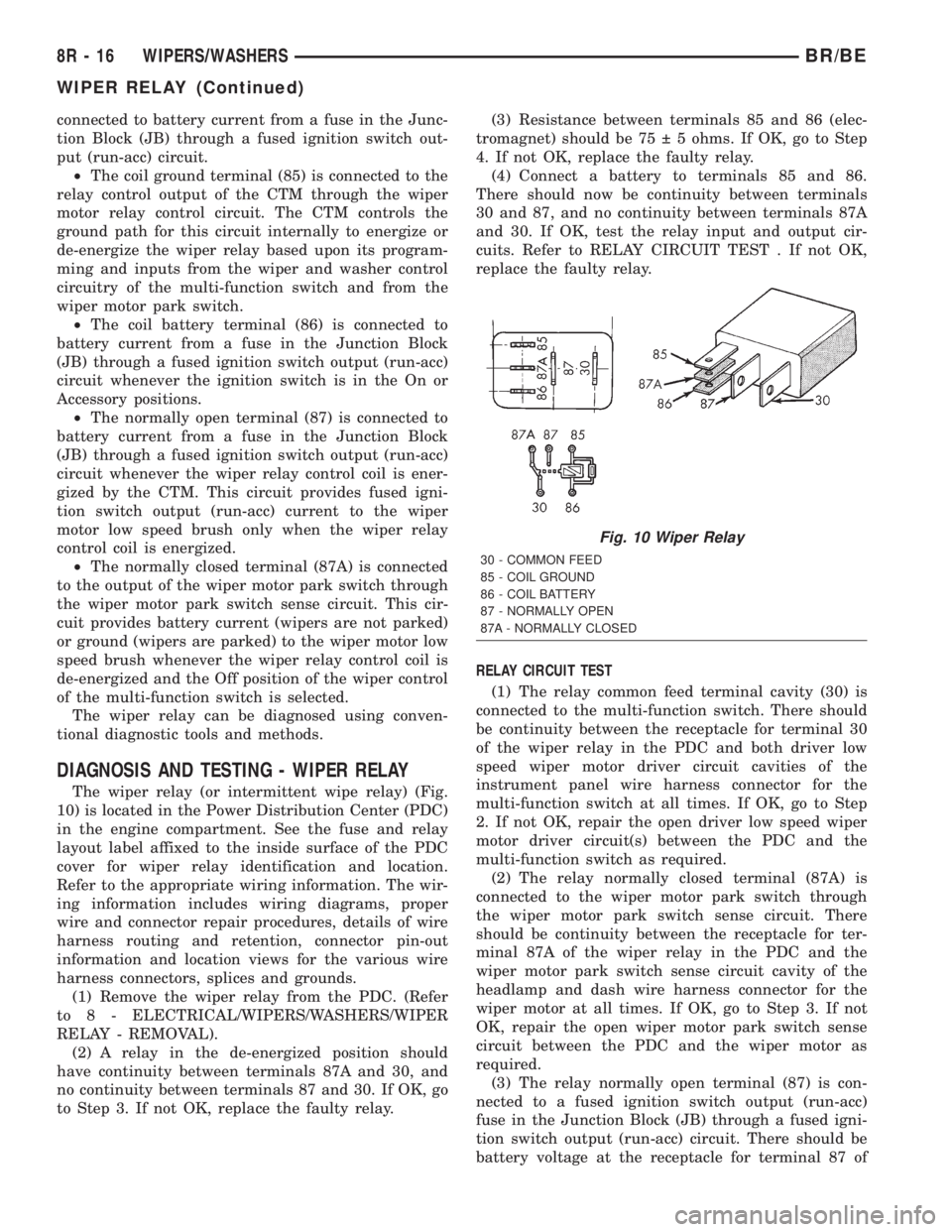
The wiper relay (or intermittent wipe relay) (Fig.
10) is located in the Power Distribution Center (PDC)
in the engine compartment. See the fuse and relay
layout label affixed to the inside surface of the PDC
cover for wiper relay identification and location.
Refer to the appropriate wiring information. The wir-
ing information includes wiring diagrams, proper
wire and connector repair procedures, details of wire
harness routing and retention, connector pin-out
information and location views for the various wire
harness connectors, splices and grounds.
(1) Remove the wiper relay from the PDC. (Refer
to 8 - ELECTRICAL/WIPERS/WASHERS/WIPER
RELAY - REMOVAL).
(2) A relay in the de-energized position should
have continuity between terminals 87A and 30, and
no continuity between terminals 87 and 30. If OK, go
to Step 3. If not OK, replace the faulty relay.(3) Resistance between terminals 85 and 86 (elec-
tromagnet) should be 75 5 ohms. If OK, go to Step
4. If not OK, replace the faulty relay.
(4) Connect a battery to terminals 85 and 86.
There should now be continuity between terminals
30 and 87, and no continuity between terminals 87A
and 30. If OK, test the relay input and output cir-
cuits. Refer to RELAY CIRCUIT TEST . If not OK,
replace the faulty relay.
RELAY CIRCUIT TEST
(1) The relay common feed terminal cavity (30) is
connected to the multi-function switch. There should
be continuity between the receptacle for terminal 30
of the wiper relay in the PDC and both driver low
speed wiper motor driver circuit cavities of the
instrument panel wire harness connector for the
multi-function switch at all times. If OK, go to Step
2. If not OK, repair the open driver low speed wiper
motor driver circuit(s) between the PDC and the
multi-function switch as required.
(2) The relay normally closed terminal (87A) is
connected to the wiper motor park switch through
the wiper motor park switch sense circuit. There
should be continuity between the receptacle for ter-
minal 87A of the wiper relay in the PDC and the
wiper motor park switch sense circuit cavity of the
headlamp and dash wire harness connector for the
wiper motor at all times. If OK, go to Step 3. If not
OK, repair the open wiper motor park switch sense
circuit between the PDC and the wiper motor as
required.
(3) The relay normally open terminal (87) is con-
nected to a fused ignition switch output (run-acc)
fuse in the Junction Block (JB) through a fused igni-
tion switch output (run-acc) circuit. There should be
battery voltage at the receptacle for terminal 87 of
Fig. 10 Wiper Relay
30 - COMMON FEED
85 - COIL GROUND
86 - COIL BATTERY
87 - NORMALLY OPEN
87A - NORMALLY CLOSED
8R - 16 WIPERS/WASHERSBR/BE
WIPER RELAY (Continued)
Page 664 of 2255
8W-01 WIRING DIAGRAM INFORMATION
TABLE OF CONTENTS
page page
WIRING DIAGRAM INFORMATION
DESCRIPTION
DESCRIPTION - HOW TO USE WIRING
DIAGRAMS...........................1
DESCRIPTION - CIRCUIT INFORMATION....4
DESCRIPTION - CIRCUIT FUNCTIONS......4
DESCRIPTION - SECTION IDENTIFICATION
AND INFORMATION....................6
DESCRIPTION - CONNECTOR, GROUND
AND SPLICE INFORMATION..............6
WARNINGS - GENERAL...................7
DIAGNOSIS AND TESTING - WIRING
HARNESS............................7
STANDARD PROCEDURE
STANDARD PROCEDURE -
ELECTROSTATIC DISCHARGE (ESD)
SENSITIVE DEVICES...................8
STANDARD PROCEDURE - TESTING OF
VOLTAGE POTENTIAL...................8
STANDARD PROCEDURE - TESTING FOR
CONTINUITY..........................9STANDARD PROCEDURE - TESTING FOR A
SHORT TO GROUND...................9
STANDARD PROCEDURE - TESTING FOR A
SHORT TO GROUND ON FUSES
POWERING SEVERAL LOADS............9
STANDARD PROCEDURE - TESTING FOR A
VOLTAGE DROP.......................9
SPECIAL TOOLS
WIRING/TERMINAL.....................9
CONNECTOR
REMOVAL.............................10
INSTALLATION.........................10
DIODE
REMOVAL.............................13
INSTALLATION.........................13
TERMINAL
REMOVAL.............................13
INSTALLATION.........................13
WIRE
STANDARD PROCEDURE - WIRE SPLICING . . 13
WIRING DIAGRAM
INFORMATION
DESCRIPTION
DESCRIPTION - HOW TO USE WIRING
DIAGRAMS
DaimlerChrysler Corporation wiring diagrams are
designed to provide information regarding the vehi-
cles wiring content. In order to effectively use the
wiring diagrams to diagnose and repair
DaimlerChrysler Corporation vehicles, it is important
to understand all of their features and characteris-
tics.
Diagrams are arranged such that the power (B+)
side of the circuit is placed near the top of the page,
and the ground (B-) side of the circuit is placed near
the bottom of the page (Fig. 1).All switches, components, and modules are shown
in the at rest position with the doors closed and the
key removed from the ignition (Fig. 2).
Components are shown two ways. A solid line
around a component indicates that the component is
complete. A dashed line around the component indi-
cates that the component is being shown is not com-
plete. Incomplete components have a reference
number to indicate the page where the component is
shown complete.
It is important to realize that no attempt is made
on the diagrams to represent components and wiring
as they appear on the vehicle. For example, a short
piece of wire is treated the same as a long one. In
addition, switches and other components are shown
as simply as possible, with regard to function only.
BR/BE8W-01 WIRING DIAGRAM INFORMATION 8W - 01 - 1
Page 667 of 2255
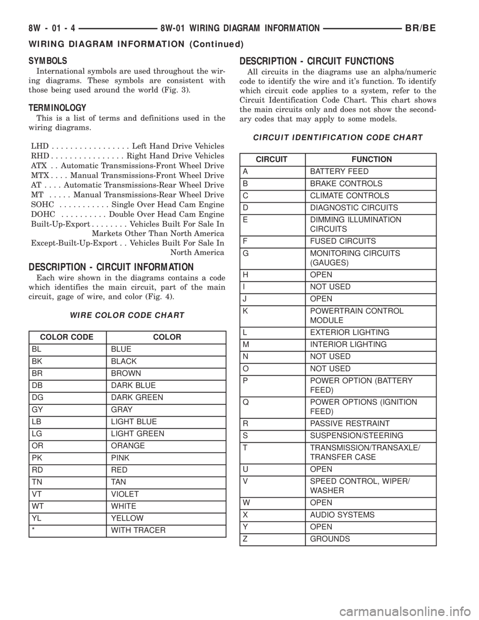
SYMBOLS
International symbols are used throughout the wir-
ing diagrams. These symbols are consistent with
those being used around the world (Fig. 3).
TERMINOLOGY
This is a list of terms and definitions used in the
wiring diagrams.
LHD .................Left Hand Drive Vehicles
RHD................Right Hand Drive Vehicles
ATX . . Automatic Transmissions-Front Wheel Drive
MTX....Manual Transmissions-Front Wheel Drive
AT ....Automatic Transmissions-Rear Wheel Drive
MT .....Manual Transmissions-Rear Wheel Drive
SOHC...........Single Over Head Cam Engine
DOHC..........Double Over Head Cam Engine
Built-Up-Export........ Vehicles Built For Sale In
Markets Other Than North America
Except-Built-Up-Export . . Vehicles Built For Sale In
North America
DESCRIPTION - CIRCUIT INFORMATION
Each wire shown in the diagrams contains a code
which identifies the main circuit, part of the main
circuit, gage of wire, and color (Fig. 4).
WIRE COLOR CODE CHART
COLOR CODE COLOR
BL BLUE
BK BLACK
BR BROWN
DB DARK BLUE
DG DARK GREEN
GY GRAY
LB LIGHT BLUE
LG LIGHT GREEN
OR ORANGE
PK PINK
RD RED
TN TAN
VT VIOLET
WT WHITE
YL YELLOW
* WITH TRACER
DESCRIPTION - CIRCUIT FUNCTIONS
All circuits in the diagrams use an alpha/numeric
code to identify the wire and it's function. To identify
which circuit code applies to a system, refer to the
Circuit Identification Code Chart. This chart shows
the main circuits only and does not show the second-
ary codes that may apply to some models.
CIRCUIT IDENTIFICATION CODE CHART
CIRCUIT FUNCTION
A BATTERY FEED
B BRAKE CONTROLS
C CLIMATE CONTROLS
D DIAGNOSTIC CIRCUITS
E DIMMING ILLUMINATION
CIRCUITS
F FUSED CIRCUITS
G MONITORING CIRCUITS
(GAUGES)
H OPEN
I NOT USED
J OPEN
K POWERTRAIN CONTROL
MODULE
L EXTERIOR LIGHTING
M INTERIOR LIGHTING
N NOT USED
O NOT USED
P POWER OPTION (BATTERY
FEED)
Q POWER OPTIONS (IGNITION
FEED)
R PASSIVE RESTRAINT
S SUSPENSION/STEERING
T TRANSMISSION/TRANSAXLE/
TRANSFER CASE
U OPEN
V SPEED CONTROL, WIPER/
WASHER
W OPEN
X AUDIO SYSTEMS
Y OPEN
Z GROUNDS
8W - 01 - 4 8W-01 WIRING DIAGRAM INFORMATIONBR/BE
WIRING DIAGRAM INFORMATION (Continued)
Page 672 of 2255
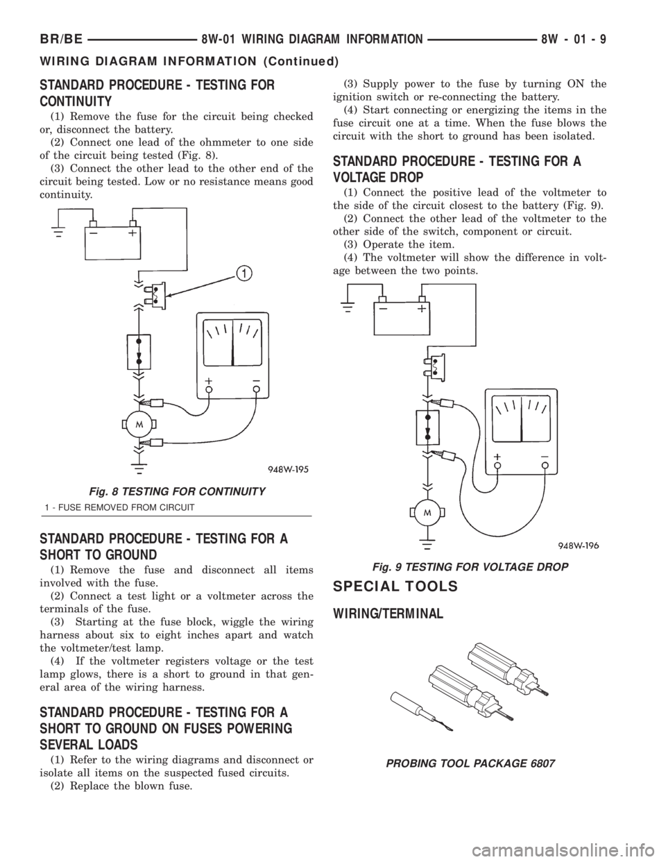
STANDARD PROCEDURE - TESTING FOR
CONTINUITY
(1) Remove the fuse for the circuit being checked
or, disconnect the battery.
(2) Connect one lead of the ohmmeter to one side
of the circuit being tested (Fig. 8).
(3) Connect the other lead to the other end of the
circuit being tested. Low or no resistance means good
continuity.
STANDARD PROCEDURE - TESTING FOR A
SHORT TO GROUND
(1) Remove the fuse and disconnect all items
involved with the fuse.
(2) Connect a test light or a voltmeter across the
terminals of the fuse.
(3) Starting at the fuse block, wiggle the wiring
harness about six to eight inches apart and watch
the voltmeter/test lamp.
(4) If the voltmeter registers voltage or the test
lamp glows, there is a short to ground in that gen-
eral area of the wiring harness.
STANDARD PROCEDURE - TESTING FOR A
SHORT TO GROUND ON FUSES POWERING
SEVERAL LOADS
(1) Refer to the wiring diagrams and disconnect or
isolate all items on the suspected fused circuits.
(2) Replace the blown fuse.(3) Supply power to the fuse by turning ON the
ignition switch or re-connecting the battery.
(4) Start connecting or energizing the items in the
fuse circuit one at a time. When the fuse blows the
circuit with the short to ground has been isolated.
STANDARD PROCEDURE - TESTING FOR A
VOLTAGE DROP
(1) Connect the positive lead of the voltmeter to
the side of the circuit closest to the battery (Fig. 9).
(2) Connect the other lead of the voltmeter to the
other side of the switch, component or circuit.
(3) Operate the item.
(4) The voltmeter will show the difference in volt-
age between the two points.
SPECIAL TOOLS
WIRING/TERMINAL
Fig. 8 TESTING FOR CONTINUITY
1 - FUSE REMOVED FROM CIRCUIT
Fig. 9 TESTING FOR VOLTAGE DROP
PROBING TOOL PACKAGE 6807
BR/BE8W-01 WIRING DIAGRAM INFORMATION 8W - 01 - 9
WIRING DIAGRAM INFORMATION (Continued)