fuse diagram DODGE RAM 2002 Service Workshop Manual
[x] Cancel search | Manufacturer: DODGE, Model Year: 2002, Model line: RAM, Model: DODGE RAM 2002Pages: 2255, PDF Size: 62.07 MB
Page 2143 of 2255

(4) Connect the battery negative cable.
BLOWER MOTOR RELAY
DESCRIPTION
The blower motor relay is an International Stan-
dards Organization (ISO)-type relay. The relay is an
electromechanical device that switches battery cur-
rent from a fuse in the Power Distribution Center
(PDC) directly to the blower motor. The relay is ener-
gized when the relay coil is provided a voltage signal
by the ignition switch. This arrangement reduces the
amount of battery current that must flow through
the ignition switch.
OPERATION
The blower motor relay control circuit is protected
by a fuse located in the junction block. When the
relay is de-energized, the blower motor receives no
battery current.The blower motor relay is located in the PDC in
the engine compartment. Refer to the PDC label for
blower motor relay identification and location.
The blower motor relay cannot be repaired and, if
faulty or damaged, it must be replaced.
DIAGNOSIS AND TESTING - BLOWER MOTOR
RELAY
RELAY TEST
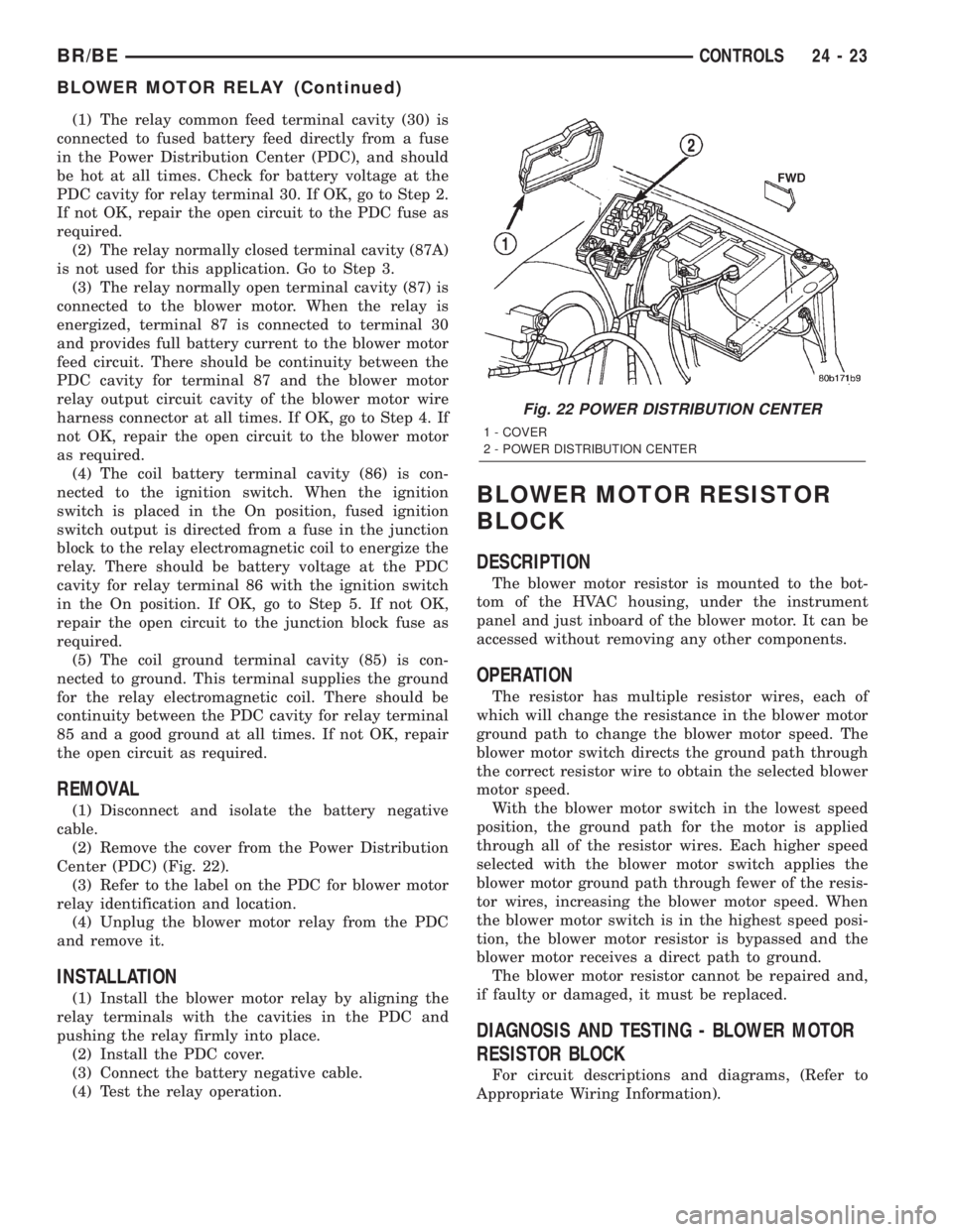
The blower motor relay (Fig. 21) is located in the
Power Distribution Center (PDC). Remove the blower
motor relay from the PDC to perform the following
tests:
(1) A relay in the de-energized position should
have continuity between terminals 87A and 30, and
no continuity between terminals 87 and 30. If OK, go
to Step 2. If not OK, replace the faulty relay.
(2) Resistance between terminals 85 and 86 (elec-
tromagnet) should be 75 5 ohms. If OK, go to Step
3. If not OK, replace the faulty relay.
(3) Connect a battery to terminals 85 and 86.
There should now be continuity between terminals
30 and 87, and no continuity between terminals 87A
and 30. If OK, see Relay Circuit Test below. If not
OK, replace the faulty relay.
RELAY CIRCUIT TEST
For circuit descriptions and diagrams, (Refer to
Appropriate Wiring Information).
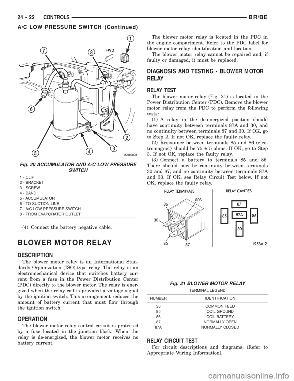
Fig. 20 ACCUMULATOR AND A/C LOW PRESSURE
SWITCH
1 - CLIP
2 - BRACKET
3 - SCREW
4 - BAND
5 - ACCUMULATOR
6 - TO SUCTION LINE
7 - A/C LOW PRESSURE SWITCH
8 - FROM EVAPORATOR OUTLET
Fig. 21 BLOWER MOTOR RELAY
TERMINAL LEGEND
NUMBER IDENTIFICATION
30 COMMON FEED
85 COIL GROUND
86 COIL BATTERY
87 NORMALLY OPEN
87A NORMALLY CLOSED
24 - 22 CONTROLSBR/BE
A/C LOW PRESSURE SWITCH (Continued)
Page 2144 of 2255

(1) The relay common feed terminal cavity (30) is
connected to fused battery feed directly from a fuse
in the Power Distribution Center (PDC), and should
be hot at all times. Check for battery voltage at the
PDC cavity for relay terminal 30. If OK, go to Step 2.
If not OK, repair the open circuit to the PDC fuse as
required.
(2) The relay normally closed terminal cavity (87A)
is not used for this application. Go to Step 3.
(3) The relay normally open terminal cavity (87) is
connected to the blower motor. When the relay is
energized, terminal 87 is connected to terminal 30
and provides full battery current to the blower motor
feed circuit. There should be continuity between the
PDC cavity for terminal 87 and the blower motor
relay output circuit cavity of the blower motor wire
harness connector at all times. If OK, go to Step 4. If
not OK, repair the open circuit to the blower motor
as required.
(4) The coil battery terminal cavity (86) is con-
nected to the ignition switch. When the ignition
switch is placed in the On position, fused ignition
switch output is directed from a fuse in the junction
block to the relay electromagnetic coil to energize the
relay. There should be battery voltage at the PDC
cavity for relay terminal 86 with the ignition switch
in the On position. If OK, go to Step 5. If not OK,
repair the open circuit to the junction block fuse as
required.
(5) The coil ground terminal cavity (85) is con-
nected to ground. This terminal supplies the ground
for the relay electromagnetic coil. There should be
continuity between the PDC cavity for relay terminal
85 and a good ground at all times. If not OK, repair
the open circuit as required.
REMOVAL
(1) Disconnect and isolate the battery negative
cable.
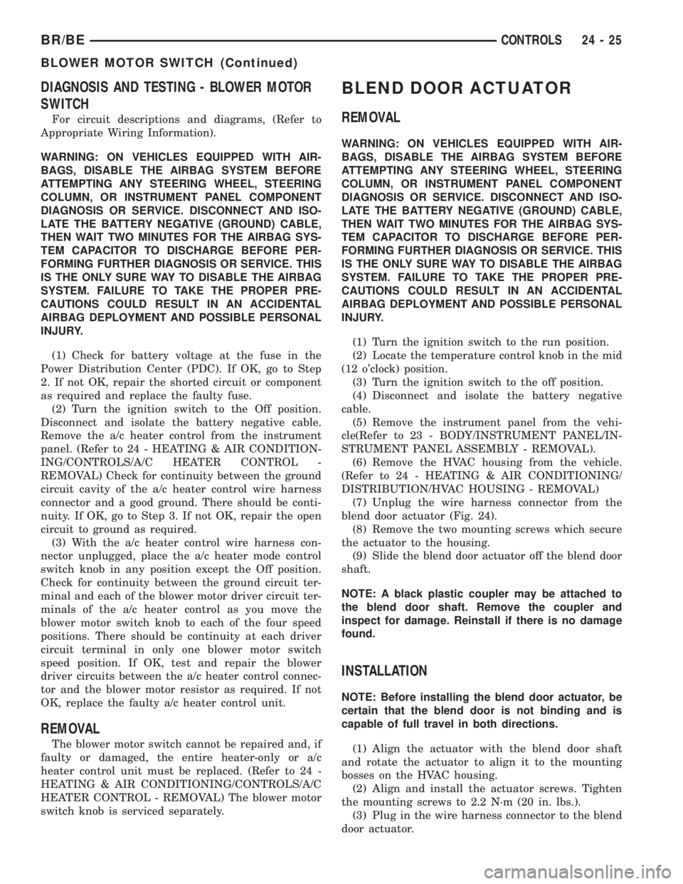
(2) Remove the cover from the Power Distribution
Center (PDC) (Fig. 22).
(3) Refer to the label on the PDC for blower motor
relay identification and location.
(4) Unplug the blower motor relay from the PDC
and remove it.
INSTALLATION
(1) Install the blower motor relay by aligning the
relay terminals with the cavities in the PDC and
pushing the relay firmly into place.
(2) Install the PDC cover.
(3) Connect the battery negative cable.
(4) Test the relay operation.
BLOWER MOTOR RESISTOR
BLOCK
DESCRIPTION
The blower motor resistor is mounted to the bot-
tom of the HVAC housing, under the instrument
panel and just inboard of the blower motor. It can be
accessed without removing any other components.
OPERATION
The resistor has multiple resistor wires, each of
which will change the resistance in the blower motor
ground path to change the blower motor speed. The
blower motor switch directs the ground path through
the correct resistor wire to obtain the selected blower
motor speed.
With the blower motor switch in the lowest speed
position, the ground path for the motor is applied
through all of the resistor wires. Each higher speed
selected with the blower motor switch applies the
blower motor ground path through fewer of the resis-
tor wires, increasing the blower motor speed. When
the blower motor switch is in the highest speed posi-
tion, the blower motor resistor is bypassed and the
blower motor receives a direct path to ground.
The blower motor resistor cannot be repaired and,
if faulty or damaged, it must be replaced.
DIAGNOSIS AND TESTING - BLOWER MOTOR
RESISTOR BLOCK
For circuit descriptions and diagrams, (Refer to
Appropriate Wiring Information).
Fig. 22 POWER DISTRIBUTION CENTER
1 - COVER
2 - POWER DISTRIBUTION CENTER
BR/BECONTROLS 24 - 23
BLOWER MOTOR RELAY (Continued)
Page 2146 of 2255

DIAGNOSIS AND TESTING - BLOWER MOTOR
SWITCH
For circuit descriptions and diagrams, (Refer to
Appropriate Wiring Information).
WARNING: ON VEHICLES EQUIPPED WITH AIR-
BAGS, DISABLE THE AIRBAG SYSTEM BEFORE
ATTEMPTING ANY STEERING WHEEL, STEERING
COLUMN, OR INSTRUMENT PANEL COMPONENT
DIAGNOSIS OR SERVICE. DISCONNECT AND ISO-
LATE THE BATTERY NEGATIVE (GROUND) CABLE,
THEN WAIT TWO MINUTES FOR THE AIRBAG SYS-
TEM CAPACITOR TO DISCHARGE BEFORE PER-
FORMING FURTHER DIAGNOSIS OR SERVICE. THIS
IS THE ONLY SURE WAY TO DISABLE THE AIRBAG
SYSTEM. FAILURE TO TAKE THE PROPER PRE-
CAUTIONS COULD RESULT IN AN ACCIDENTAL
AIRBAG DEPLOYMENT AND POSSIBLE PERSONAL
INJURY.
(1) Check for battery voltage at the fuse in the
Power Distribution Center (PDC). If OK, go to Step
2. If not OK, repair the shorted circuit or component
as required and replace the faulty fuse.
(2) Turn the ignition switch to the Off position.
Disconnect and isolate the battery negative cable.
Remove the a/c heater control from the instrument
panel. (Refer to 24 - HEATING & AIR CONDITION-
ING/CONTROLS/A/C HEATER CONTROL -
REMOVAL) Check for continuity between the ground
circuit cavity of the a/c heater control wire harness
connector and a good ground. There should be conti-
nuity. If OK, go to Step 3. If not OK, repair the open
circuit to ground as required.
(3) With the a/c heater control wire harness con-
nector unplugged, place the a/c heater mode control
switch knob in any position except the Off position.
Check for continuity between the ground circuit ter-
minal and each of the blower motor driver circuit ter-
minals of the a/c heater control as you move the
blower motor switch knob to each of the four speed
positions. There should be continuity at each driver
circuit terminal in only one blower motor switch
speed position. If OK, test and repair the blower
driver circuits between the a/c heater control connec-
tor and the blower motor resistor as required. If not
OK, replace the faulty a/c heater control unit.
REMOVAL
The blower motor switch cannot be repaired and, if
faulty or damaged, the entire heater-only or a/c
heater control unit must be replaced. (Refer to 24 -
HEATING & AIR CONDITIONING/CONTROLS/A/C
HEATER CONTROL - REMOVAL) The blower motor
switch knob is serviced separately.
BLEND DOOR ACTUATOR
REMOVAL
WARNING: ON VEHICLES EQUIPPED WITH AIR-
BAGS, DISABLE THE AIRBAG SYSTEM BEFORE
ATTEMPTING ANY STEERING WHEEL, STEERING
COLUMN, OR INSTRUMENT PANEL COMPONENT
DIAGNOSIS OR SERVICE. DISCONNECT AND ISO-
LATE THE BATTERY NEGATIVE (GROUND) CABLE,
THEN WAIT TWO MINUTES FOR THE AIRBAG SYS-
TEM CAPACITOR TO DISCHARGE BEFORE PER-
FORMING FURTHER DIAGNOSIS OR SERVICE. THIS
IS THE ONLY SURE WAY TO DISABLE THE AIRBAG
SYSTEM. FAILURE TO TAKE THE PROPER PRE-
CAUTIONS COULD RESULT IN AN ACCIDENTAL
AIRBAG DEPLOYMENT AND POSSIBLE PERSONAL
INJURY.
(1) Turn the ignition switch to the run position.
(2) Locate the temperature control knob in the mid
(12 o'clock) position.
(3) Turn the ignition switch to the off position.
(4) Disconnect and isolate the battery negative
cable.
(5) Remove the instrument panel from the vehi-
cle(Refer to 23 - BODY/INSTRUMENT PANEL/IN-
STRUMENT PANEL ASSEMBLY - REMOVAL).
(6) Remove the HVAC housing from the vehicle.
(Refer to 24 - HEATING & AIR CONDITIONING/
DISTRIBUTION/HVAC HOUSING - REMOVAL)
(7) Unplug the wire harness connector from the
blend door actuator (Fig. 24).
(8) Remove the two mounting screws which secure
the actuator to the housing.
(9) Slide the blend door actuator off the blend door
shaft.
NOTE: A black plastic coupler may be attached to
the blend door shaft. Remove the coupler and
inspect for damage. Reinstall if there is no damage
found.
INSTALLATION
NOTE: Before installing the blend door actuator, be
certain that the blend door is not binding and is
capable of full travel in both directions.
(1) Align the actuator with the blend door shaft
and rotate the actuator to align it to the mounting
bosses on the HVAC housing.
(2) Align and install the actuator screws. Tighten
the mounting screws to 2.2 N´m (20 in. lbs.).
(3) Plug in the wire harness connector to the blend
door actuator.
BR/BECONTROLS 24 - 25
BLOWER MOTOR SWITCH (Continued)
Page 2153 of 2255

DIAGNOSIS AND TESTING - BLOWER MOTOR
WARNING: ON VEHICLES EQUIPPED WITH AIR-
BAGS, DISABLE THE AIRBAG SYSTEM BEFORE
ATTEMPTING ANY STEERING WHEEL, STEERING
COLUMN, OR INSTRUMENT PANEL COMPONENT
DIAGNOSIS OR SERVICE. DISCONNECT AND ISO-
LATE THE BATTERY NEGATIVE (GROUND) CABLE,
THEN WAIT TWO MINUTES FOR THE AIRBAG SYS-
TEM CAPACITOR TO DISCHARGE BEFORE PER-
FORMING FURTHER DIAGNOSIS OR SERVICE. THIS
IS THE ONLY SURE WAY TO DISABLE THE AIRBAG
SYSTEM. FAILURE TO TAKE THE PROPER PRE-
CAUTIONS COULD RESULT IN AN ACCIDENTAL
AIRBAG DEPLOYMENT AND POSSIBLE PERSONAL
INJURY.
For circuit descriptions and diagrams, (Refer to
Appropriate Wiring Information). Possible causes of
an inoperative blower motor include:
²Faulty fuse
²Faulty blower motor circuit wiring or wire har-
ness connectors
²Faulty blower motor resistor
²Faulty blower motor relay
²Faulty blower motor switch
²Faulty a/c heater mode control switch
²Faulty blower motor.
Possible causes of the blower motor not operating
in all speeds include:
²Faulty fuse
²Faulty blower motor switch
²Faulty blower motor resistor
²Faulty blower motor relay
²Faulty blower motor circuit wiring or wire har-
ness connectors.
VIBRATION
Possible causes of blower motor vibration include:
²Improper blower motor mounting
²Improper blower wheel mounting
²Blower wheel out of balance or deformed
²Blower motor faulty.
NOISE
To verify that the blower is the source of the noise,
unplug the blower motor wire harness connector and
operate the HVAC system. If the noise goes away,
possible causes include:
²Foreign material in the HVAC housing
²Improper blower motor mounting
²Improper blower wheel mounting
²Blower motor faulty.
REMOVAL
(1) Disconnect and isolate the battery negative
cable.
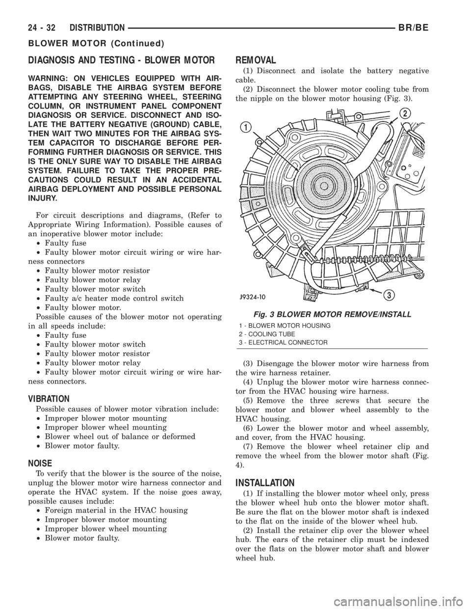
(2) Disconnect the blower motor cooling tube from
the nipple on the blower motor housing (Fig. 3).
(3) Disengage the blower motor wire harness from
the wire harness retainer.
(4) Unplug the blower motor wire harness connec-
tor from the HVAC housing wire harness.
(5) Remove the three screws that secure the
blower motor and blower wheel assembly to the
HVAC housing.
(6) Lower the blower motor and wheel assembly,
and cover, from the HVAC housing.
(7) Remove the blower wheel retainer clip and
remove the wheel from the blower motor shaft (Fig.
4).
INSTALLATION
(1) If installing the blower motor wheel only, press
the blower wheel hub onto the blower motor shaft.
Be sure the flat on the blower motor shaft is indexed
to the flat on the inside of the blower wheel hub.
(2) Install the retainer clip over the blower wheel
hub. The ears of the retainer clip must be indexed
over the flats on the blower motor shaft and blower
wheel hub.
Fig. 3 BLOWER MOTOR REMOVE/INSTALL
1 - BLOWER MOTOR HOUSING
2 - COOLING TUBE
3 - ELECTRICAL CONNECTOR
24 - 32 DISTRIBUTIONBR/BE
BLOWER MOTOR (Continued)