glove box DODGE RAM 2002 Service Owner's Manual
[x] Cancel search | Manufacturer: DODGE, Model Year: 2002, Model line: RAM, Model: DODGE RAM 2002Pages: 2255, PDF Size: 62.07 MB
Page 575 of 2255
The RKE transmitter operates on two Duracell
DL2016, Panasonic CR2016 (or equivalent) batteries.
Typical battery life is from one to two years. The
RKE transmitter cannot be repaired and, if faulty or
damaged, it must be replaced.
OPERATION
See the owner's manual in the vehicle glove box for
more information on the features, use and operation
of the Remote Keyless Entry (RKE) transmitters.
DIAGNOSIS AND TESTING - REMOTE KEYLESS
ENTRY TRANSMITTER
(1) Replace the Remote Keyless Entry (RKE)
transmitter batteries. (Refer to 8 - ELECTRICAL/
POWER LOCKS/REMOTE KEYLESS ENTRY
TRANSMITTER - STANDARD PROCEDURE - RKE
TRANSMITTER BATTERIES). Test each of the RKE
transmitter functions. If OK, discard the faulty bat-
teries. If not OK, go to Step 2.
(2) Program the suspect RKE transmitter and
another known good transmitter into the RKE
receiver. (Refer to 8 - ELECTRICAL/POWER
LOCKS/REMOTE KEYLESS ENTRY TRANSMIT-
TER - STANDARD PROCEDURE - RKE TRANS-
MITTER PROGRAMMING).
(3) Test the RKE system operation with both
transmitters. If both transmitters fail to operate the
power lock system, a DRBIIItscan tool is required
for further diagnosis of the RKE system. Refer to the
appropriate diagnostic information. If the known
good RKE transmitter operates the power locks and
the suspect transmitter does not, replace the faulty
RKE transmitter.
NOTE: Be certain to perform the RKE Transmitter
Programming procedure again following this test.
This procedure will erase the access code of the
test transmitter from the RKE receiver.
STANDARD PROCEDURE
STANDARD PROCEDURE - RKE TRANSMITTER
PROGRAMMING
To program the Remote Keyless Entry (RKE)
transmitter access codes into the RKE receiver in the
high-line or premium Central Timer Module (CTM)
requires the use of a DRBIIItscan tool. Refer to the
appropriate diagnostic information.
STANDARD PROCEDURE - REMOTE KEYLESS
ENTRY TRANSMITTER BATTERIES
The Remote Keyless Entry (RKE) transmitter case
snaps open and shut for battery access. To replace
the RKE transmitter batteries:
(1) Using a trim stick or a thin coin, gently pry at
the notch in the center seam of the RKE transmitter
case halves located near the key ring until the two
halves unsnap.
(2) Lift the back half of the transmitter case off of
the RKE transmitter.
(3) Remove the two batteries from the RKE trans-
mitter.
(4) Replace the two batteries with new Duracell
DL2016, or their equivalent. Be certain that the bat-
teries are installed with their polarity correctly ori-
ented.
(5) Align the two RKE transmitter case halves
with each other, and squeeze them firmly and evenly
together using hand pressure until they snap back
into place.
POWER LOCK SWITCH
DESCRIPTION
The power lock system can be controlled by a two-
way momentary switch integral to the power window
and lock switch and bezel unit on the trim panel of
each front door. Each power lock switch is illumi-
nated by a Light-Emitting Diode (LED) that is inte-
gral to the switch paddle. The LED of each switch is
illuminated whenever the ignition switch is in the
On position.
The power lock switches and their LEDs cannot be
adjusted or repaired and, if faulty or damaged, the
entire power window and lock switch and bezel unit
must be replaced.
OPERATION
On models with a base version of the Central
Timer Module (CTM), the power lock switches are
hard-wired to the power lock motors. The power lock
switch provides the correct battery and ground feeds
to the power lock motors to lock or unlock the door
latches.
On models with a high-line or premium version of
the CTM, the power lock switch controls battery cur-
rent signals to the lock and unlock sense inputs of
the CTM. The CTM then relays the correct battery
and ground feeds to the power lock motors to lock or
unlock the door latches.
8N - 8 POWER LOCKSBR/BE
REMOTE KEYLESS ENTRY TRANSMITTER (Continued)
Page 578 of 2255
POWER MIRRORS
TABLE OF CONTENTS
page page
POWER MIRRORS
DESCRIPTION.........................11
OPERATION...........................11
AUTOMATIC DAY / NIGHT MIRROR
DESCRIPTION.........................11
OPERATION...........................12
DIAGNOSIS AND TESTING - AUTOMATIC
DAY/NIGHT MIRROR...................12
REMOVAL.............................13
INSTALLATION.........................13
POWER MIRROR SWITCH
DESCRIPTION.........................13OPERATION...........................13
REMOVAL.............................13
INSTALLATION.........................14
SIDEVIEW MIRROR
DESCRIPTION.........................14
OPERATION...........................14
DIAGNOSIS AND TESTING - SIDEVIEW
MIRROR............................14
REMOVAL.............................15
POWER MIRRORS
DESCRIPTION
AUTOMATIC DAY / NIGHT MIRROR
The automatic day/night mirror system is able to
automatically change the reflectance of the inside
rear view mirror in order to reduce the glare of head-
lamps approaching the vehicle from the rear. The
automatic day/night rear view mirror receives bat-
tery current through a fuse in the junction block only
when the ignition switch is in the On position.
OUTSIDE REAR VIEW MIRROR
The heated mirror option includes an electric heat-
ing grid behind the mirror glass in each outside mir-
ror, which can clear the mirror glass of ice, snow, or
fog. The heating grid receives fused battery current
through the heated mirror relay in the heater and air
conditioner control only when the ignition switch is
in the On position, and the heated mirror system is
turned on. (Refer to 8 - ELECTRICAL/HEATED
MIRRORS - DESCRIPTION) for more information.
Refer to the owner's manual in the vehicle glove
box for more information on the features, use and
operation of the power mirror system.
OPERATION
AUTOMATIC DAY / NIGHT MIRROR
A switch located on the bottom of the automatic
day/night mirror housing allows the vehicle operator
to select whether the automatic dimming feature is
operational. When the automatic day/night mirror isturned on, the mirror switch is lighted by an integral
Light-Emitting Diode (LED). The mirror will auto-
matically disable its self-dimming feature whenever
the vehicle is being driven in reverse.
Refer to the owner's manual in the vehicle glove
box for more information on the features, use and
operation of the automatic day/night mirror system.
OUTSIDE REAR VIEW MIRROR
The heated mirror option includes an electric heat-
ing grid behind the mirror glass in each outside mir-
ror, which can clear the mirror glass of ice, snow, or
fog. The heating grid receives fused battery current
through the heated mirror relay in the heater and air
conditioner control only when the ignition switch is
in the On position, and the heated mirror system is
turned on. (Refer to 8 - ELECTRICAL/HEATED
MIRRORS - OPERATION) for more information.
Refer to the owner's manual in the vehicle glove
box for more information on the features, use and
operation of the power mirror system.
AUTOMATIC DAY / NIGHT
MIRROR
DESCRIPTION
The automatic day/night mirror uses a thin layer
of electrochromic material between two pieces of con-
ductive glass to make up the face of the mirror.
When the mirror switch is in the On position, two
photocell sensors are used by the mirror circuitry to
monitor external light levels and adjust the reflec-
tance of the mirror.
BR/BEPOWER MIRRORS 8N - 11
Page 583 of 2255
POWER SEAT SYSTEM
TABLE OF CONTENTS
page page
POWER SEAT SYSTEM
DESCRIPTION.........................16
OPERATION...........................16
DIAGNOSIS AND TESTING - POWER SEAT
SYSTEM............................16
DRIVER POWER SEAT SWITCH
DESCRIPTION.........................17
OPERATION...........................17
DIAGNOSIS AND TESTING - DRIVER POWER
SEAT SWITCH........................17
REMOVAL.............................18
INSTALLATION.........................18
LUMBAR CONTROL SWITCH
DESCRIPTION.........................18
OPERATION...........................19
REMOVAL.............................19
LUMBAR MOTOR
DESCRIPTION.........................19OPERATION...........................19
DIAGNOSIS AND TESTING - LUMBAR MOTOR . 19
PASSENGER POWER SEAT SWITCH
DESCRIPTION.........................20
OPERATION...........................20
DIAGNOSIS AND TESTING - PASSENGER
POWER SEAT SWITCH.................20
REMOVAL.............................21
INSTALLATION.........................21
POWER SEAT TRACK
DESCRIPTION.........................21
OPERATION...........................22
DIAGNOSIS AND TESTING - POWER SEAT
TRACK.............................22
REMOVAL.............................22
INSTALLATION.........................22
POWER SEAT SYSTEM
DESCRIPTION
The power seat system option allows the driver (or
passenger on SLT Plus with power seats) to electri-
cally adjust the seat position for optimum control and
comfort using the power seat switches located on the
outboard seat cushion side shield. The power seat
system allows the seating position to be adjusted for-
ward, rearward, front up, front down, rear up, or
rear down. The power seat system receives battery
current through a fuse in the Power Distribution
Center and a circuit breaker in the junction block,
regardless of the ignition switch position.
The quad cab models equipped with the power seat
option also feature a power operated lumbar support
in the seat back. The power lumbar support allows
the user to inflate or deflate a bladder located in the
lower seat back to achieve optimum comfort and sup-
port in the lower lumbar region of the spinal column.
The power lumbar support shares the battery feed
circuit of the power seat system.
The power seat system includes the power seat
adjuster and motors unit, the power lumbar support
bladder and electric pump (quad cab only), the power
seat switch, and the circuit breaker. Following are
general descriptions of the major components in the
power seat system. Refer toHeated Seat Systemfor information on the individually controlled heated
front seats. Refer to the owner's manual in the vehi-
cle glove box for more information on the features,
use and operation of the power seat system.
OPERATION
The power seat system allows the driver and/or
front passenger seating positions to be adjusted elec-
trically and independently using the separate power
seat switches found on the outboard seat cushion
side shield of each front seat. See the owner's manual
in the vehicle glove box for more information on the
features, use and operation of the power seat system.
DIAGNOSIS AND TESTING - POWER SEAT
SYSTEM
Before any testing of the power seat system is
attempted, the battery should be fully-charged and
all wire harness connections and pins cleaned and
tightened to ensure proper continuity and grounds.
For circuit descriptions and diagrams, refer to Wiring
Diagrams.
With the dome lamp on, apply the power seat
switch in the direction of the failure. If the dome
lamp dims, the seat may be jamming. Check under
and behind the seat for binding or obstructions. If
the dome lamp does not dim, proceed with testing of
the individual components and circuits.
8N - 16 POWER SEAT SYSTEMBR/BE
Page 584 of 2255
DRIVER POWER SEAT SWITCH
DESCRIPTION
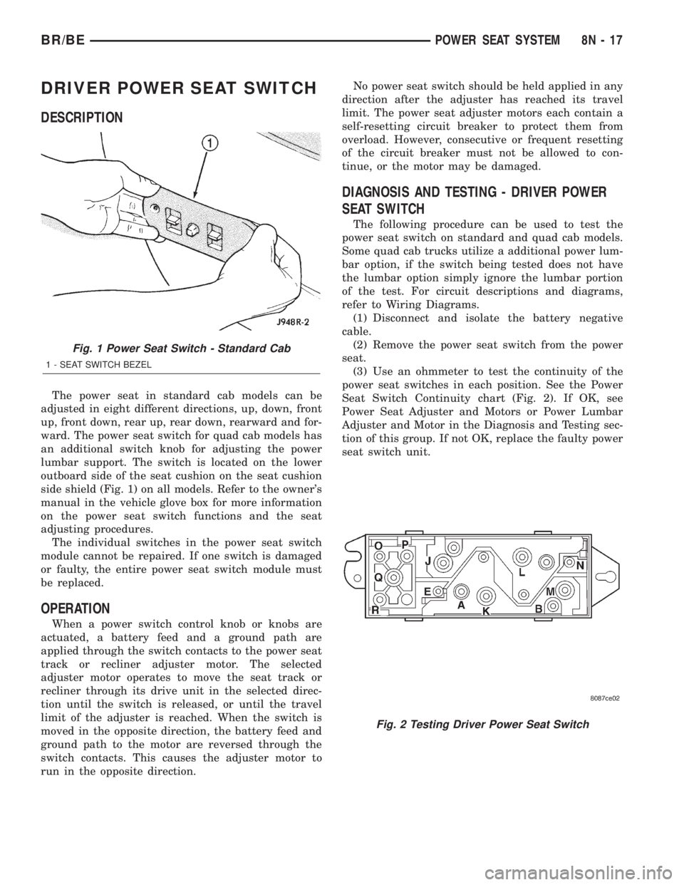
The power seat in standard cab models can be
adjusted in eight different directions, up, down, front
up, front down, rear up, rear down, rearward and for-
ward. The power seat switch for quad cab models has
an additional switch knob for adjusting the power
lumbar support. The switch is located on the lower
outboard side of the seat cushion on the seat cushion
side shield (Fig. 1) on all models. Refer to the owner's
manual in the vehicle glove box for more information
on the power seat switch functions and the seat
adjusting procedures.
The individual switches in the power seat switch
module cannot be repaired. If one switch is damaged
or faulty, the entire power seat switch module must
be replaced.
OPERATION
When a power switch control knob or knobs are
actuated, a battery feed and a ground path are
applied through the switch contacts to the power seat
track or recliner adjuster motor. The selected
adjuster motor operates to move the seat track or
recliner through its drive unit in the selected direc-
tion until the switch is released, or until the travel
limit of the adjuster is reached. When the switch is
moved in the opposite direction, the battery feed and
ground path to the motor are reversed through the
switch contacts. This causes the adjuster motor to
run in the opposite direction.No power seat switch should be held applied in any
direction after the adjuster has reached its travel
limit. The power seat adjuster motors each contain a
self-resetting circuit breaker to protect them from
overload. However, consecutive or frequent resetting
of the circuit breaker must not be allowed to con-
tinue, or the motor may be damaged.
DIAGNOSIS AND TESTING - DRIVER POWER
SEAT SWITCH
The following procedure can be used to test the
power seat switch on standard and quad cab models.
Some quad cab trucks utilize a additional power lum-
bar option, if the switch being tested does not have
the lumbar option simply ignore the lumbar portion
of the test. For circuit descriptions and diagrams,
refer to Wiring Diagrams.
(1) Disconnect and isolate the battery negative
cable.
(2) Remove the power seat switch from the power
seat.
(3) Use an ohmmeter to test the continuity of the
power seat switches in each position. See the Power
Seat Switch Continuity chart (Fig. 2). If OK, see
Power Seat Adjuster and Motors or Power Lumbar
Adjuster and Motor in the Diagnosis and Testing sec-
tion of this group. If not OK, replace the faulty power
seat switch unit.
Fig. 1 Power Seat Switch - Standard Cab
1 - SEAT SWITCH BEZEL
Fig. 2 Testing Driver Power Seat Switch
BR/BEPOWER SEAT SYSTEM 8N - 17
Page 587 of 2255
PASSENGER POWER SEAT
SWITCH
DESCRIPTION
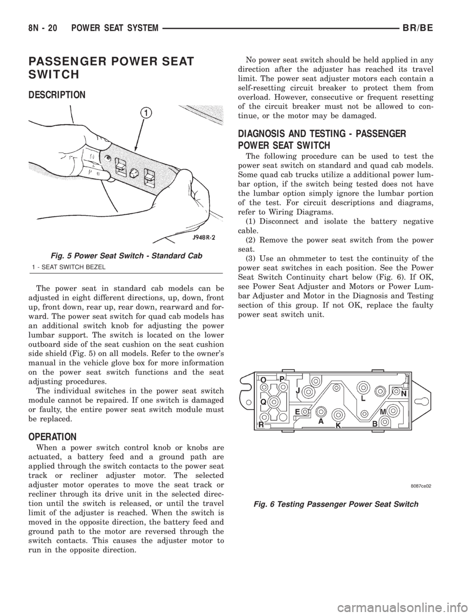
The power seat in standard cab models can be
adjusted in eight different directions, up, down, front
up, front down, rear up, rear down, rearward and for-
ward. The power seat switch for quad cab models has
an additional switch knob for adjusting the power
lumbar support. The switch is located on the lower
outboard side of the seat cushion on the seat cushion
side shield (Fig. 5) on all models. Refer to the owner's
manual in the vehicle glove box for more information
on the power seat switch functions and the seat
adjusting procedures.
The individual switches in the power seat switch
module cannot be repaired. If one switch is damaged
or faulty, the entire power seat switch module must
be replaced.
OPERATION
When a power switch control knob or knobs are
actuated, a battery feed and a ground path are
applied through the switch contacts to the power seat
track or recliner adjuster motor. The selected
adjuster motor operates to move the seat track or
recliner through its drive unit in the selected direc-
tion until the switch is released, or until the travel
limit of the adjuster is reached. When the switch is
moved in the opposite direction, the battery feed and
ground path to the motor are reversed through the
switch contacts. This causes the adjuster motor to
run in the opposite direction.No power seat switch should be held applied in any
direction after the adjuster has reached its travel
limit. The power seat adjuster motors each contain a
self-resetting circuit breaker to protect them from
overload. However, consecutive or frequent resetting
of the circuit breaker must not be allowed to con-
tinue, or the motor may be damaged.
DIAGNOSIS AND TESTING - PASSENGER
POWER SEAT SWITCH
The following procedure can be used to test the
power seat switch on standard and quad cab models.
Some quad cab trucks utilize a additional power lum-
bar option, if the switch being tested does not have
the lumbar option simply ignore the lumbar portion
of the test. For circuit descriptions and diagrams,
refer to Wiring Diagrams.
(1) Disconnect and isolate the battery negative
cable.
(2) Remove the power seat switch from the power
seat.
(3) Use an ohmmeter to test the continuity of the
power seat switches in each position. See the Power
Seat Switch Continuity chart below (Fig. 6). If OK,
see Power Seat Adjuster and Motors or Power Lum-
bar Adjuster and Motor in the Diagnosis and Testing
section of this group. If not OK, replace the faulty
power seat switch unit.
Fig. 5 Power Seat Switch - Standard Cab
1 - SEAT SWITCH BEZEL
Fig. 6 Testing Passenger Power Seat Switch
8N - 20 POWER SEAT SYSTEMBR/BE
Page 590 of 2255
POWER WINDOWS
TABLE OF CONTENTS
page page
POWER WINDOWS
DESCRIPTION.........................23
OPERATION...........................23
DIAGNOSIS AND TESTING - POWER
WINDOWS...........................23
POWER WINDOW SWITCH
DESCRIPTION.........................24
OPERATION...........................24
DIAGNOSIS AND TESTING - POWER
WINDOW SWITCH.....................24REMOVAL.............................25
INSTALLATION.........................26
WINDOW MOTOR
DESCRIPTION.........................26
DIAGNOSIS AND TESTING - WINDOW
MOTOR .............................26
REMOVAL.............................26
POWER WINDOWS
DESCRIPTION
Power windows are available as factory-installed
optional equipment on this model. The power lock
system is included on vehicles equipped with the
power window option.
OPERATION
The power window system allows each of the front
door windows to be raised and lowered electrically by
actuating a switch on the trim panel of each respec-
tive door. Additionally, the master switch on the
driver side door trim panel allows the driver to raise
or lower the passenger side front door window. The
power window system receives battery feed through a
circuit breaker in the junction block, only when the
ignition switch is in the On position.
The power window system includes the power win-
dow switches on each front door trim panel, the cir-
cuit breaker in the junction block, and the power
window motors inside each front door. This group
covers diagnosis and service of only the electrical
components in the power window system. For service
of mechanical components, such as the regulator, lift
plate, window tracks, or glass refer to Group 23 -
Body.
Refer to the owner's manual in the vehicle glove
box for more information on the features, use and
operation of the power window system.
DIAGNOSIS AND TESTING - POWER
WINDOWS
For circuit descriptions and diagrams, refer to the
appropriate wiring information. The wiring informa-
tion includes wiring diagrams, proper wire and con-
nector repair procedures, details of wire harnessrouting and retention, connector pin-out information
and location views for the various wire harness con-
nectors, splices and grounds.
ALL WINDOWS INOPERATIVE
(1) Check the circuit breaker in the junction block.
If OK, go to Step 2. If not OK, replace the faulty cir-
cuit breaker.
(2) Disconnect and isolate the battery negative
cable. Remove the power window and lock switch and
bezel unit from the driver side front door trim panel.
Unplug the wire harness connector from the switch
and bezel unit.
(3) Check for continuity between the ground cir-
cuit cavity of the switch and bezel unit wire harness
connector and a good ground. If OK, (Refer to 8 -
ELECTRICAL/POWER WINDOWS/POWER WIN-
DOW SWITCH - DIAGNOSIS AND TESTING). If not
OK, repair the circuit to ground as required.
ONE WINDOW INOPERATIVE
The window glass must be free to slide up and
down for the power window motor to function prop-
erly. If the glass is not free to move up and down, the
motor will overload and trip the integral circuit
breaker. To determine if the glass is free, disconnect
the regulator plate from the glass. Then slide the
window up and down by hand.
There is an alternate method to check if the glass
is free. Position the glass between the up and down
stops. Then, shake the glass in the door. Check that
the glass can be moved slightly from side to side,
front to rear, and up and down. Then check that the
glass is not bound tight in the tracks. If the glass is
free, proceed with the diagnosis that follows. If the
glass is not free, (Refer to 23 - BODY/DOOR -
FRONT/DOOR GLASS - REMOVAL).
BR/BEPOWER WINDOWS 8N - 23
Page 594 of 2255
RESTRAINTS
TABLE OF CONTENTS
page page
RESTRAINTS
DESCRIPTION..........................1
OPERATION............................2
WARNING.............................3
DIAGNOSIS AND TESTING - AIRBAG SYSTEM . 4
STANDARD PROCEDURE
STANDARD PROCEDURE - HANDLING
NON-DEPLOYED AIRBAGS...............4
STANDARD PROCEDURE - SERVICE
AFTER AN AIRBAG DEPLOYMENT.........4
STANDARD PROCEDURE - VERIFICATION
TEST................................5
SPECIAL TOOLS - AIRBAG SYSTEM.........6
AIRBAG CONTROL MODULE
DESCRIPTION..........................6
OPERATION............................6
REMOVAL.............................7
INSTALLATION..........................8
CHILD TETHER
REMOVAL.............................9
INSTALLATION..........................9
CLOCKSPRING
DESCRIPTION.........................10
OPERATION...........................10
STANDARD PROCEDURE - CLOCKSPRING
CENTERING.........................11
REMOVAL.............................12
INSTALLATION.........................13
DRIVER AIRBAG
DESCRIPTION.........................14
OPERATION...........................14
REMOVAL.............................14
DISASSEMBLY.........................15
ASSEMBLY............................16
INSTALLATION.........................17
FRONT SEAT BELT & RETRACTOR
REMOVAL
REMOVAL - STANDARD CAB............18REMOVAL - CLUB/QUAD CAB............19
INSTALLATION
INSTALLATION - STANDARD CAB.........19
INSTALLATION - CLUB/QUAD CAB........20
FRONT SEAT BELT BUCKLE
REMOVAL.............................20
INSTALLATION.........................20
PASSENGER AIRBAG
DESCRIPTION.........................21
OPERATION...........................21
REMOVAL.............................21
INSTALLATION.........................23
PASSENGER AIRBAG ON/OFF SWITCH
DESCRIPTION.........................23
OPERATION...........................24
REMOVAL.............................24
INSTALLATION.........................25
REAR SEAT BELT & RETRACTOR
REMOVAL.............................26
INSTALLATION.........................26
REAR SEAT BELT BUCKLE
REMOVAL.............................27
INSTALLATION.........................27
SEAT BELT SWITCH
DESCRIPTION.........................28
OPERATION...........................28
DIAGNOSIS AND TESTING - SEAT BELT
SWITCH............................28
SEAT BELT TURNING LOOP ADJUSTER
REMOVAL.............................29
INSTALLATION.........................29
TURNING LOOP HGT ADJUSTER KNOB
REMOVAL.............................30
INSTALLATION.........................30
RESTRAINTS
DESCRIPTION
A dual front airbag system is standard factory-in-
stalled safety equipment on this model. The airbag
system is a passive, inflatable, Supplemental
Restraint System (SRS) and vehicles with this equip-
ment can be readily identified by the ªSRS - AIR-
BAGº logo molded into the driver airbag trim coverin the center of the steering wheel and also into the
passenger airbag door on the instrument panel above
the glove box (Fig. 1). Vehicles with the airbag sys-
tem can also be identified by the airbag indicator,
which will illuminate in the instrument cluster for
about seven seconds as a bulb test each time the
ignition switch is turned to the On position.
The dual front airbag system consists of the follow-
ing major components, which are described in further
detail elsewhere in this service manual:
BR/BERESTRAINTS 8O - 1
Page 595 of 2255
²Airbag Control Module- The Airbag Control
Module (ACM) is located in a stamped mounting
bracket on the floor panel transmission tunnel, below
the center of the instrument panel.
²Airbag Indicator- The airbag indicator is inte-
gral to the ElectroMechanical Instrument Cluster
(EMIC), which is located on the instrument panel in
front of the driver.
²Clockspring- The clockspring is located near
the top of the steering column, directly beneath the
steering wheel.
²Driver Airbag- The driver airbag is located in
the center of the steering wheel, beneath the driver
airbag trim cover.
²Driver Knee Blocker- The driver knee blocker
is a molded plastic structural unit secured to the
back side of and integral to the instrument panel
steering column opening cover.
²Passenger Airbag- The passenger airbag is
located on the instrument panel, beneath the passen-
ger airbag door on the instrument panel above the
glove box on the passenger side of the vehicle.
²Passenger Airbag On/Off Switch- The pas-
senger airbag on/off switch is located in a dedicated
opening in the upper right corner of the instrument
panel cluster bezel, to the right of the center panel
outlets of the climate control system.
²Passenger Knee Blocker- The passenger knee
blocker is a structural reinforcement that is integral
to and concealed within the glove box door.
The ACM and the EMIC each contain a central
processing unit and programming that allow them to
communicate with each other using the Chrysler Col-
lision Detection (CCD) data bus network. This
method of communication is used for control of the
airbag indicator on all models. (Refer to 8 - ELEC-
TRICAL/ELECTRONIC CONTROL MODULES/
COMMUNICATION - DESCRIPTION).Hard wired circuitry connects the airbag system
components to each other through the electrical sys-
tem of the vehicle. These hard wired circuits are
integral to several wire harnesses, which are routed
throughout the vehicle and retained by many differ-
ent methods. These circuits may be connected to each
other, to the vehicle electrical system, and to the air-
bag system components through the use of a combi-
nation of soldered splices, splice block connectors,
and many different types of wire harness terminal
connectors and insulators. Refer to the appropriate
wiring information. The wiring information includes
wiring diagrams, proper wire and connector repair
procedures, further details on wire harness routing
and retention, as well as pin-out and location views
for the various wire harness connectors, splices and
grounds.OPERATION
The airbag system is referred to as a supplemental
restraint system because it was designed and is
intended to enhance the protection for the front seat
occupants of the vehicleonlywhen used in conjunc-
tion with the seat belts. It is referred to as a passive
system because the vehicle occupants are not
required to do anything to make it work. The pri-
mary passenger restraints in this or any other vehi-
cle are the standard equipment factory-installed seat
belts. Seat belts are referred to as an active restraint
because the vehicle occupants are required to physi-
cally fasten and properly adjust these restraints in
order to benefit from them. The vehicle occupants
must be wearing their seat belts in order to obtain
the maximum safety benefit from the factory-in-
stalled airbag system.
The airbag system electrical circuits are continu-
ously monitored and controlled by a microprocessor
and software contained within the Airbag Control
Module (ACM). An airbag indicator in the ElectroMe-
chanical Instrument Cluster (EMIC) lights for about
seven seconds as a bulb test each time the ignition
switch is turned to the On or Start positions. Follow-
ing the bulb test, the airbag indicator is turned on or
off by the ACM to indicate the status of the airbag
system. If the airbag indicator comes on at any time
other than during the bulb test, it indicates that
there is a problem in the airbag system electrical cir-
cuits. Such a problem may cause the airbags not to
deploy when required, or to deploy when not
required.
The clockspring on the top of the steering column
allows a continuous electrical circuit to be main-
tained between the stationary steering column and
the driver airbag inflator, which rotates with the
steering wheel. The passenger airbag on/off switch
allows the passenger side airbag to be disabled when
Fig. 1 SRS Logo
8O - 2 RESTRAINTSBR/BE
RESTRAINTS (Continued)
Page 596 of 2255
circumstances necessitate that a child, or an adult
with certain medical conditions be placed in the front
passenger seating position. Refer to the owner's man-
ual in the vehicle glove box for specific recommenda-
tions concerning the specific circumstances where the
passenger airbag on/off switch should be used to dis-
able the passenger airbag.
Deployment of the airbags depends upon the angle
and severity of the impact. The airbag system is
designed to deploy upon a frontal impact within a
thirty degree angle from either side of the vehicle
center line. Deployment is not based upon vehicle
speed; rather, deployment is based upon the rate of
deceleration as measured by the forces of gravity (G
force) upon the airbag system impact sensor, which is
integral to the ACM. When a frontal impact is severe
enough, the microprocessor in the ACM signals the
inflator units of both airbag modules to deploy the
airbags. During a frontal vehicle impact, the knee
blockers work in concert with properly fastened and
adjusted seat belts to restrain both the driver and
the front seat passenger in the proper position for an
airbag deployment. The knee blockers also absorb
and distribute the crash energy from the driver and
the front seat passenger to the structure of the
instrument panel.
Typically, the driver and front seat passenger recall
more about the events preceding and following a col-
lision than they have of the airbag deployment itself.
This is because the airbag deployment and deflation
occur so rapidly. In a typical 48 kilometer-per-hour
(30 mile-per-hour) barrier impact, from the moment
of impact until both airbags are fully inflated takes
about 40 milliseconds. Within one to two seconds
from the moment of impact, both airbags are almost
entirely deflated. The times cited for these events are
approximations, which apply only to a barrier impact
at the given speed. Actual times will vary somewhat,
depending upon the vehicle speed, impact angle,
severity of the impact, and the type of collision.
When the ACM monitors a problem in any of the
airbag system circuits or components, it stores a
fault code or Diagnostic Trouble Code (DTC) in its
memory circuit and sends an electronic message to
the EMIC to turn on the airbag indicator. Proper
testing of the airbag system components, the
Chrysler Collision Detection (CCD) data bus, the
data bus message inputs to and outputs from the
EMIC or the ACM, as well as the retrieval or erasure
of a DTC from the ACM requires the use of a
DRBIIItscan tool. Refer to the appropriate diagnos-
tic information.
See the owner's manual in the vehicle glove box for
more information on the features, use and operation
of all of the factory-installed passenger restraints,
including the airbag system.WARNING
WARNING: THE AIRBAG SYSTEM IS A SENSITIVE,
COMPLEX ELECTROMECHANICAL UNIT. BEFORE
ATTEMPTING TO DIAGNOSE OR SERVICE ANY AIR-
BAG SYSTEM OR RELATED STEERING WHEEL,
STEERING COLUMN, OR INSTRUMENT PANEL
COMPONENTS YOU MUST FIRST DISCONNECT
AND ISOLATE THE BATTERY NEGATIVE (GROUND)
CABLE. THEN WAIT TWO MINUTES FOR THE SYS-
TEM CAPACITOR TO DISCHARGE BEFORE FUR-
THER SYSTEM SERVICE. THIS IS THE ONLY SURE
WAY TO DISABLE THE AIRBAG SYSTEM. FAILURE
TO DO THIS COULD RESULT IN ACCIDENTAL AIR-
BAG DEPLOYMENT AND POSSIBLE PERSONAL
INJURY.
WARNING: THE DRIVER AIRBAG INFLATOR UNIT
CONTAINS SODIUM AZIDE AND POTASSIUM
NITRATE. THESE MATERIALS ARE POISONOUS
AND EXTREMELY FLAMMABLE. CONTACT WITH
ACID, WATER, OR HEAVY METALS MAY PRODUCE
HARMFUL AND IRRITATING GASES (SODIUM
HYDROXIDE IS FORMED IN THE PRESENCE OF
MOISTURE) OR COMBUSTIBLE COMPOUNDS. THE
PASSENGER AIRBAG UNIT CONTAINS ARGON GAS
PRESSURIZED TO OVER 2500 PSI. DO NOT
ATTEMPT TO DISMANTLE AN AIRBAG UNIT OR
TAMPER WITH ITS INFLATOR. DO NOT PUNCTURE,
INCINERATE, OR BRING INTO CONTACT WITH
ELECTRICITY. DO NOT STORE AT TEMPERATURES
EXCEEDING 93É C (200É F).
WARNING: REPLACE AIRBAG SYSTEM COMPO-
NENTS ONLY WITH PARTS SPECIFIED IN THE
DAIMLERCHRYSLER MOPAR PARTS CATALOG.
SUBSTITUTE PARTS MAY APPEAR INTERCHANGE-
ABLE, BUT INTERNAL DIFFERENCES MAY RESULT
IN INFERIOR OCCUPANT PROTECTION.
WARNING: THE FASTENERS, SCREWS, AND
BOLTS ORIGINALLY USED FOR THE AIRBAG SYS-
TEM COMPONENTS HAVE SPECIAL COATINGS
AND ARE SPECIFICALLY DESIGNED FOR THE AIR-
BAG SYSTEM. THEY MUST NEVER BE REPLACED
WITH ANY SUBSTITUTES. ANY TIME A NEW FAS-
TENER IS NEEDED, REPLACE IT WITH THE COR-
RECT FASTENERS PROVIDED IN THE SERVICE
PACKAGE OR SPECIFIED IN THE
DAIMLERCHRYSLER MOPAR PARTS CATALOG.
BR/BERESTRAINTS 8O - 3
RESTRAINTS (Continued)
Page 614 of 2255
PASSENGER AIRBAG
DESCRIPTION
The rearward facing surface of the passenger air-
bag door above the glove box is the most visible part
of the passenger airbag. The airbag used in this
model is a Next Generation-type that complies with
revised federal airbag standards to deploy with less
force than those used in some prior models. The pas-
senger airbag is located in the instrument panel in
front of the front seat passenger seating position,
where it is secured to the instrument panel. Con-
cealed beneath the passenger airbag door are the
folded airbag cushion, the airbag retainer or housing,
and the airbag inflator. The airbag inflator is a
hybrid-type unit that is secured to and sealed within
the stamped steel airbag housing along with the
folded airbag cushion. The airbag housing stamping
also includes the two mounting brackets, one front
and one rear. The front bracket is secured beneath
the instrument panel top cover with screws to the
instrument panel structural support. The rear
bracket is secured with screws to the upper glove box
opening reinforcement. A yellow connector on the end
of a short, two-wire pigtail harness connects the pas-
senger airbag inflator to the vehicle electrical system.
The molded plastic passenger airbag door has pre-
determined breakout lines concealed beneath its dec-
orative cover. The lower edge of the passenger airbag
door is secured to the airbag housing, and includes
the two passenger side panel outlets. The sides and
upper edges are secured to the instrument panel top
cover with five molded tabs that are each fit with a
small metal retainer. The five retainers are snapped
into five slotted receptacles located around the sides
and top of the airbag door opening in the instrument
panel top cover. Following a passenger airbag deploy-
ment, the passenger airbag and airbag door unit
must be replaced. The passenger airbag cannot be
repaired, and must be replaced if faulty or in any
way damaged. The passenger airbag door is serviced
only as a unit with the passenger airbag, and
includes the two passenger side heating and air con-
ditioning panel outlet housings and barrels.
OPERATION
The passenger airbag is deployed by an electrical
signal generated by the Airbag Control Module
(ACM) through the passenger airbag line 1 and line 2
(or squib) circuits. The hybrid-type inflator assembly
includes a small canister of highly compressed argon
gas. When the ACM sends the proper electrical signal
to the airbag inflator, the electrical energy generates
enough heat to ignite chemical pellets within the
inflator. Once ignited, these chemical pellets burn
rapidly and produce the pressure necessary to rup-ture a containment disk in the argon gas canister.
The inflator and argon gas canister are sealed to the
airbag cushion so that all of the released argon gas is
directed into the airbag cushion, causing the cushion
to inflate. As the cushion inflates, the passenger air-
bag door will split at the breakout lines and the door
will pivot out of the way. Following an airbag deploy-
ment, the airbag cushion quickly deflates by venting
the argon gas through the porous fabric material
used on each end panel of the airbag cushion.
Some of the chemicals used to create the pressure
to burst the argon gas containment disk are consid-
ered hazardous in their solid state, before they are
burned, but they are securely sealed within the air-
bag inflator. However, the gas that is produced when
the chemicals are burned is harmless. A small
amount of residue from the burned chemicals may
cause some temporary discomfort if it contacts the
skin, eyes, or breathing passages. If skin or eye irri-
tation is noticed, rinse the affected area with plenty
of cool, clean water. If breathing passages are irri-
tated, move to another area where there is plenty of
clean, fresh air to breath. If the irritation is not alle-
viated by these actions, contact a physician immedi-
ately.
REMOVAL
WARNING: DISABLE THE AIRBAG SYSTEM
BEFORE ATTEMPTING ANY STEERING WHEEL,
STEERING COLUMN, OR INSTRUMENT PANEL
COMPONENT DIAGNOSIS OR SERVICE. DISCON-
NECT AND ISOLATE THE BATTERY NEGATIVE
(GROUND) CABLE, THEN WAIT TWO MINUTES FOR
THE AIRBAG SYSTEM CAPACITOR TO DISCHARGE
BEFORE PERFORMING FURTHER DIAGNOSIS OR
SERVICE. THIS IS THE ONLY SURE WAY TO DIS-
ABLE THE AIRBAG SYSTEM. FAILURE TO TAKE
THE PROPER PRECAUTIONS COULD RESULT IN
ACCIDENTAL AIRBAG DEPLOYMENT AND POSSI-
BLE PERSONAL INJURY.
WARNING: WHEN REMOVING A DEPLOYED AIR-
BAG, RUBBER GLOVES, EYE PROTECTION, AND A
LONG-SLEEVED SHIRT SHOULD BE WORN. THERE
MAY BE DEPOSITS ON THE AIRBAG UNIT AND
OTHER INTERIOR SURFACES. IN LARGE DOSES,
THESE DEPOSITS MAY CAUSE IRRITATION TO THE
SKIN AND EYES.
(1) Disconnect and isolate the battery negative
cable. If either of the airbags has not been deployed,
wait two minutes for the system capacitor to dis-
charge before further service.
BR/BERESTRAINTS 8O - 21