radio controls DODGE RAM 2002 Service Repair Manual
[x] Cancel search | Manufacturer: DODGE, Model Year: 2002, Model line: RAM, Model: DODGE RAM 2002Pages: 2255, PDF Size: 62.07 MB
Page 339 of 2255
ing diagrams, proper wire and connector repair
procedures, details of wire harness routing and
retention, connector pin-out information and location
views for the various wire harness connectors, splices
and grounds. Following are general descriptions of
the remaining major components in the standard and
optional factory-installed audio systems.
OPERATION
See the owner's manual in the vehicle glove box for
more information on the features, use and operation
of each of the available audio systems.
CENTRAL TIMER MODULE
The high-line or premium Central Timer Module
(CTM) can also control some features of the audio
system when the vehicle is equipped with the
optional RAZ radio receiver and remote radio
switches. A high-line CTM is used on high-line ver-
sions of this vehicle. A premium CTM is used on
vehicles equipped with the optional heated seats. The
CTM combines the functions of a chime/buzzer mod-
ule, an intermittent wipe module, an illuminated
entry module, a remote keyless entry module, and a
vehicle theft security system module in a single unit.
The high-line or premium CTM also controls and
integrates many of the additional electronic functions
and features included on models with this option.
The RAZ radio receiver with a remote radio switch
option is one of the features that the CTM controls.
The CTM is programmed to send switch status mes-sages over the Chrysler Collision Detection (CCD)
data bus to control the volume, seek, and pre-set sta-
tion advance functions of the RAZ radio receiver. The
CTM monitors the status of the remote radio
switches located on the steering wheel through a
hard wired circuit. The CTM then sends the proper
switch status messages to the radio receiver. The
electronic circuitry within the radio receiver responds
to the switch status messages it receives by adjusting
the radio settings as requested.
Refer to Electrical, Body Control/Central Timer
Module for more information on the high-line CTM.
Refer to Remote Radio Switch in Description and
Operation for more information on this component.
In addition, radio receivers connected to the CCD
data bus have several audio system functions that
can be diagnosed using a DRBIIItscan tool. Refer to
the proper Diagnostic Procedures manual for more
information on DRBIIIttesting of the audio systems.
DIAGNOSIS AND TESTING - AUDIO
WARNING: ON VEHICLES EQUIPPED WITH AIR-
BAGS, REFER TO ELECTRICAL, RESTRAINTS
BEFORE ATTEMPTING ANY STEERING WHEEL,
STEERING COLUMN, OR INSTRUMENT PANEL
COMPONENT DIAGNOSIS OR SERVICE. FAILURE
TO TAKE THE PROPER PRECAUTIONS COULD
RESULT IN ACCIDENTAL AIRBAG DEPLOYMENT
AND POSSIBLE PERSONAL INJURY.
Audio System Diagnosis
CONDITION POSSIBLE CAUSE CORRECTION
NO AUDIO 1. Fuse faulty. 1. Check radio fuses in junction block. Replace faulty
fuses, if required.
2. Radio connector faulty. 2. Check for loose or corroded radio connections. Repair,
if required.
3. Wiring faulty. 3. Check for battery voltage at radio connector. Repair
wiring, if required.
4. Ground faulty. 4. Check for continuity between radio chassis and a
known good ground. There should be continuity. Repair
ground, if required.
5. Radio faulty. 5. Refer to Radio in the Diagnosis and Testing section of
this group.
6. Speakers faulty. 6. Refer to Speaker in the Diagnosis and Testing section
of this group.
7. Amplifier faulty (if
equipped).7. Refer to Speaker in the Diagnosis and Testing section
of this group.
8A - 2 AUDIOBR/BE
AUDIO (Continued)
Page 354 of 2255
(5) Install the driver side airbag module onto the
steering wheel. Refer to Electrical, Restraints for the
procedures.
(6) Reconnect the battery negative cable.
SPEAKER
DESCRIPTION
STANDARD
The standard equipment speaker system includes
speakers in four locations. One full-range 15.2 by
22.9 centimeter (6.0 by 9.0 inch) speaker is located in
each front door. There is also one full-range 13.3 cen-
timeter (5.25 inch) diameter speaker located in each
rear cab side panel for the standard cab and the club
cab models, or in each rear door of the quad cab mod-
els.
PREMIUM
The optional premium speaker system features
Infinity model speakers in six locations. Each of the
standard front door speakers are replaced with Infin-
ity model speakers that include integral dual 30 watt
amplifiers. Each of the standard rear speakers is also
replaced by an Infinity model speaker. The premium
speaker system also includes an additional Infinity
tweeter mounted in the A-pillar garnish molding. The
total available power of the premium speaker system
is about 120 watts.
OPERATION
STANDARD
Each of the four full-range speakers used in the
standard speaker system is driven by the amplifier
that is integral to the factory-installed radio receiver.
For complete circuit diagrams, refer to the appropri-
ate wiring information. The wiring information
includes wiring diagrams, proper wire and connector
repair procedures, details of wire harness routing
and retention, connector pin-out information and
location views for the various wire harness connec-
tors, splices and grounds.
PREMIUM
The Infinity speakers used in the premium speaker
system are driven by dual amplifiers that are inte-
gral to each of the front door speakers. One of these
dual amplifiers drives the front door speaker and the
A-pillar mounted tweeter for that side of the vehicle,
while the other amplifier drives the rear speaker for
that side of the vehicle. For complete circuit dia-
grams, to refer to the appropriate wiring information.
The wiring information includes wiring diagrams,proper wire and connector repair procedures, details
of wire harness routing and retention, connector pin-
out information and location views for the various
wire harness connectors, splices and grounds.
DIAGNOSIS AND TESTING - SPEAKER
For complete circuit diagrams, refer to the appro-
priate wiring information. The wiring information
includes wiring diagrams, proper wire and connector
repair procedures, details of wire harness routing
and retention, connector pin-out information and
location views for the various wire harness connec-
tors, splices and grounds.
WARNING: ON VEHICLES EQUIPPED WITH AIR-
BAGS, REFER TO ELECTRICAL, RESTRAINTS
BEFORE ATTEMPTING ANY STEERING WHEEL,
STEERING COLUMN, OR INSTRUMENT PANEL
COMPONENT DIAGNOSIS OR SERVICE. FAILURE
TO TAKE THE PROPER PRECAUTIONS COULD
RESULT IN ACCIDENTAL AIRBAG DEPLOYMENT
AND POSSIBLE PERSONAL INJURY.
CAUTION: The speaker output of the radio receiver
is a ªfloating groundº system. Do not allow any
speaker lead to short to ground, as damage to the
radio receiver may result.
(1) Turn the ignition switch to the On position.
Turn the radio receiver on. Adjust the balance and
fader controls to check the performance of each indi-
vidual speaker. Note the speaker locations that are
not performing correctly. If only an Infinity A-pillar
or an Infinity rear speaker is inoperative, go to Step
8. If any other speaker is inoperative, go to Step 2.
NOTE: If the vehicle is equipped with the Infinity
premium speaker package and all of the speakers
are inoperative, refer to Filter, Choke, and Speaker
Relay in the Diagnosis and Testing section of this
group.
(2) Turn the radio receiver off. Turn the ignition
switch to the Off position. Disconnect and isolate the
battery negative cable. Remove the radio receiver
from the instrument panel. Check both the feed (+)
circuit and return (±) circuit cavities for the inopera-
tive speaker location(s) in the radio receiver wire
harness connectors for continuity to ground. In each
case, there should be no continuity. If OK, go to Step
3. If not OK, repair the shorted speaker feed (+)
and/or return (±) circuit(s) to the speaker as required.
(3) If the inoperative speaker is an Infinity-ampli-
fied speaker, go to Step 5. If the vehicle is equipped
with the standard speaker system, check the resis-
tance between the speaker feed (+) circuit and return
BR/BEAUDIO 8A - 17
REMOTE SWITCHES (Continued)
Page 367 of 2255
The features that the CTM supports or controls
include the following:
²Automatic Door Lock- The high-line/premium
CTM provides an optional automatic door lock fea-
ture (also known as rolling door locks). This is a pro-
grammable feature.²Central Locking- The high-line/premium CTM
provides an optional central locking/unlocking fea-
ture.
²Chimes- All versions of the CTM provide chime
service through an integral chime tone generator.
²Courtesy Lamps- The high-line/premium CTM
provides courtesy lamp control with timed load shed-
ding.
²Door Lock Inhibit- The high-line/premium
CTM provides a door lock inhibit feature.
²Enhanced Accident Response- The high-line/
premium CTM provides an optional enhanced acci-
dent response feature. This is a programmable
feature.
²Heated Seats- The premium CTM controls the
optional heated seat system by controlling the opera-
tion of the heated seat relay.
²Illuminated Entry- The high-line/premium
CTM provides a timed illuminated entry feature.
²Intermittent Wipe Control- All versions of
the CTM provide control of the intermittent wipe
delay, and wipe-after-wash features.
²Panic Mode- The high-line/premium CTM pro-
vides support for the optional RKE system panic
mode features.
²Power Lock Control- The high-line/premium
CTM provides the optional power lock system fea-
tures, including support for the automatic door lock
and door lock inhibit modes.
²Programmable Features- The high-line/pre-
mium CTM provides support for certain programma-
ble features.
²Remote Keyless Entry- The high-line/pre-
mium CTM provides the optional Remote Keyless
Entry (RKE) system features, including support for
the RKE Lock (with optional horn chirp), Unlock,
Panic, and illuminated entry modes, as well as the
ability to be programmed to recognize up to four
RKE transmitters. The RKE horn chirp is a program-
mable feature.
²Remote Radio Switch Interface- The high-
line/premium CTM monitors and transmits the sta-
tus of the optional remote radio switches.
²Speed Sensitive Intermittent Wipe Control-
The high-line/premium CTM provides the speed sen-
sitive intermittent wipe feature.
²Vehicle Theft Alarm- The high-line/premium
CTM provides control of the optional Vehicle Theft
Alarm features, including support for the central
locking/unlocking mode.
Hard wired circuitry connects the CTM to the elec-
trical system of the vehicle. These hard wired circuits
are integral to several wire harnesses, which are
routed throughout the vehicle and retained by many
different methods. These circuits may be connected to
each other, to the vehicle electrical system and to the
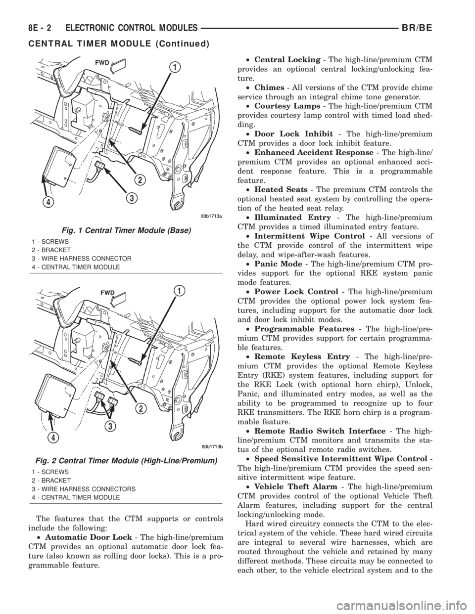
Fig. 1 Central Timer Module (Base)
1 - SCREWS
2 - BRACKET
3 - WIRE HARNESS CONNECTOR
4 - CENTRAL TIMER MODULE
Fig. 2 Central Timer Module (High-Line/Premium)
1 - SCREWS
2 - BRACKET
3 - WIRE HARNESS CONNECTORS
4 - CENTRAL TIMER MODULE
8E - 2 ELECTRONIC CONTROL MODULESBR/BE
CENTRAL TIMER MODULE (Continued)
Page 571 of 2255
OPERATION - REMOTE KEYLESS ENTRY
SYSTEM
On vehicles with the Remote Keyless Entry (RKE)
system, the power locks can be operated remotely
using the RKE transmitter. If the vehicle is so
equipped, the RKE transmitter also arms and dis-
arms the factory-installed Vehicle Theft Security Sys-
tem (VTSS). Three small, recessed buttons on the
outside of the transmitter case labelled Lock, Unlock,
and Panic allow the user to choose the function that
is desired. The RKE transmitter then sends the
appropriate Radio Frequency (RF) signal. An RF
receiver that is integral to the high-line or premium
version of the Central Timer Module (CTM) receives
the transmitted signal, then uses its internal elec-
tronic programming to determine whether the
received signal is valid and what function has been
requested. If the signal is valid, the CTM provides
the programmed features.
Besides operating the power lock system and arm-
ing or disarming the VTSS, the RKE system also
controls the following features:
²Horn Chirp- If this feature is enabled, the
CTM provides a horn chirp by internally pulling the
control coil of the horn relay to ground through a
hard wired circuit output.
²Illuminated Entry- The CTM provides illumi-
nated entry by internally controlling the current flow
to the courtesy lamps in the vehicle through a hard
wired output circuit.
²Panic Mode- The CTM provides the horn pulse
and headlight flash by internally pulling the control
coils of the horn relay and headlamp relay to ground
through hard wired circuit outputs. The CTM con-
trols the current flow to the courtesy lamps in the
vehicle through a hard wired output circuit. The
CTM also monitors the vehicle speed through elec-
tronic messages it receives from the Powertrain Con-
trol Module (PCM) over the Chrysler Collision
Detection (CCD) data bus network.
The RKE system operates on battery current
received through a fused B(+) circuit from a fuse in
the Junction Block (JB) so that the system remains
functional, regardless of the ignition switch position.
The RKE system can retain the vehicle access codes
of up to four RKE transmitters. The transmitter
codes are retained in RKE system memory, even if
the battery is disconnected. If a transmitter is faulty
or is lost, new transmitter vehicle access codes can be
programmed into the system using a DRBIIItscan
tool. Refer to the appropriate diagnostic information.
Many of the electronic features in the vehicle con-
trolled or supported by the high-line or premium ver-
sions of the CTM are programmable using the
DRBIIItscan tool. In addition, the high-line/pre-
mium CTM software is Flash compatible, whichmeans it can be reprogrammed using Flash repro-
gramming procedures. However, if any of the CTM
hardware components are damaged or faulty, the
entire CTM unit must be replaced. The hard wired
inputs or outputs of the CTM can be diagnosed using
conventional diagnostic tools and methods; however,
for diagnosis of the high-line or premium versions of
the CTM or the CCD data bus, the use of a DRBIIIt
scan tool is required. Refer to the appropriate diag-
nostic information.
DIAGNOSIS AND TESTING
DIAGNOSIS AND TESTING - POWER LOCKS
The following tests provide a preliminary diagnosis
for the power lock system usedonlyon vehicles
equipped with a base version of the Central Timer
Module (CTM). These testsdo notapply to the diag-
nosis of the power lock system used on vehicles
equipped with the optional Remote Keyless Entry
(RKE) system, which includes a high-line or premium
CTM. (Refer to 8 - ELECTRICAL/POWER LOCKS -
DIAGNOSIS AND TESTING - POWER LOCK &
REMOTE KEYLESS ENTRY SYSTEM). Refer to the
appropriate wiring information. The wiring informa-
tion includes wiring diagrams, proper wire and con-
nector repair procedures, details of wire harness
routing and retention, connector pin-out information
and location views for the various wire harness con-
nectors, splices and grounds.
PRELIMINARY TESTS
To begin this test, note the system operation while
you actuate both the Lock and Unlock functions with
the power lock switches. Then, proceed as follows:
²If the entire power lock system fails to function
with both of the power lock switches, check the fused
B(+) fuse in the Junction Block (JB). If the fuse is
OK, check the ground circuit between the driver side
power lock switch and ground (G301). If the ground
circuit is OK, proceed to the diagnosis of the power
lock motors. (Refer to 8 - ELECTRICAL/POWER
LOCKS/POWER LOCK MOTOR - DIAGNOSIS AND
TESTING).
²If the entire power lock system fails to function
with only one of the power lock switches, proceed to
diagnosis of the power lock switches. (Refer to 8 -
ELECTRICAL/POWER LOCKS/POWER LOCK
SWITCH - DIAGNOSIS AND TESTING).
²If only one power lock motor fails to operate
with both power lock switches, proceed to diagnosis
of the power lock motor. (Refer to 8 - ELECTRICAL/
POWER LOCKS/POWER LOCK MOTOR - DIAGNO-
SIS AND TESTING).
8N - 4 POWER LOCKSBR/BE
POWER LOCKS (Continued)
Page 574 of 2255
POWER LOCK MOTOR
DESCRIPTION
Models equipped with the optional power lock sys-
tem have a power operated door locking mechanism
located within each front door. The lock mechanisms
are actuated by a reversible electric power lock motor
that is integral to the door latch unit within each
front door. A single short pigtail wire with a molded
plastic connector insulator connects the door lock
motor to the vehicle electrical system through a take
out and connector of each front door wire harness.
The power lock motors cannot be adjusted or
repaired and, if faulty or damaged, the entire door
latch unit must be replaced.
OPERATION
On models with a base version of the Central
Timer Module (CTM), the power lock motor is con-
trolled by the battery and ground feeds from the
power lock switches. On models with the high-line or
premium versions of the CTM, the power lock motor
is controlled by the battery and ground feeds from
the power lock and unlock relays, which are integral
and internal to the high-line and premium versions
of the CTM. A positive and negative battery connec-
tion to the two motor terminals will cause the power
lock motor plunger to move in one direction. Revers-
ing the current through these same two connections
will cause the power lock motor plunger to move in
the opposite direction.
The power lock motors and circuits can be tested
using conventional diagnostic tools and methods.
DIAGNOSIS AND TESTING - POWER LOCK
MOTOR
On models with a base version of the Central
Timer Module (CTM), confirm proper power lock
switch operation before you proceed with this diagno-
sis. On models with a high-line or premium version
of the CTM, confirm proper power lock switch, power
lock switch output circuit, and CTM operation before
you proceed with this diagnosis. Remember, the
power lock switch controls the output to the power
lock motors on models with a base CTM, while the
CTM controls the output to the power lock motors on
models with a high-line or premium CTM. Refer to
the appropriate wiring information. The wiring infor-
mation includes wiring diagrams, proper wire and
connector repair procedures, details of wire harness
routing and retention, connector pin-out information
and location views for the various wire harness con-
nectors, splices and grounds.
(1) Check each power lock motor for correct opera-
tion while moving the power lock switch to both theLock and Unlock positions. If both of the power lock
motors are inoperative, go to Step 2. If one power
lock motor is inoperative, go to Step 3.
(2) If both of the power lock motors are inopera-
tive, the problem may be caused by one shorted
motor. Disconnecting a shorted power lock motor
from the power lock circuit will allow the good power
lock motors to operate. Disconnect the wire harness
connector from each power lock motor, one at a time,
and recheck both the lock and unlock functions by
operating the power lock switch. If both power lock
motors are still inoperative after the above test,
check for a short or open circuit between the power
lock motors and either the power lock switch (base
CTM) or the CTM (high-line or premium CTM). If
disconnecting one power lock motor causes the other
motor to become functional, go to Step 3 to test the
disconnected motor.
(3) Once it is determined which power lock motor
is inoperative, that motor can be tested as follows.
Disconnect the door wire harness connector from the
inoperative power lock motor. Apply 12 volts to the
lock and unlock driver circuit cavities of the power
lock motor pigtail wire connector to check its opera-
tion in one direction. Reverse the polarity to check
the motor operation in the opposite direction. If OK,
repair the shorted or open circuits between the power
lock motor and the power lock switch (base CTM) or
the CTM (high-line or premium CTM) as required. If
not OK, replace the faulty power lock motor.
REMOTE KEYLESS ENTRY
TRANSMITTER
DESCRIPTION
The Remote Keyless Entry (RKE) system Radio
Frequency (RF) transmitter is equipped with three
buttons, labeled Lock, Unlock, and Panic. It is also
equipped with a key ring and is designed to serve as
a key fob. The operating range of the transmitter
radio signal is up to 7 meters (23 feet) from the RKE
receiver. The RKE receiver is integral to the high-
line or premium Central Timer Module (CTM) in this
vehicle.
Each RKE transmitter has a different vehicle
access code, which must be programmed into the
memory of the RKE receiver in the vehicle in order
to operate the RKE system. The RKE receiver can
retain the access codes for up to four transmitters in
its memory. (Refer to 8 - ELECTRICAL/POWER
LOCKS/REMOTE KEYLESS ENTRY TRANSMIT-
TER - STANDARD PROCEDURE - RKE TRANS-
MITTER PROGRAMMING).
BR/BEPOWER LOCKS 8N - 7
Page 2072 of 2255
INSTRUMENT PANEL SYSTEM
TABLE OF CONTENTS
page page
INSTRUMENT PANEL SYSTEM
DESCRIPTION........................105
OPERATION..........................106
ASH RECEIVER
REMOVAL............................107
INSTALLATION........................107
CLUSTER BEZEL
REMOVAL............................108
INSTALLATION........................108
CUBBY BIN
REMOVAL............................108
INSTALLATION........................109
CUP HOLDER
REMOVAL............................109
INSTALLATION........................110
GLOVE BOX
REMOVAL
REMOVAL..........................110
DISASSEMBLY - GLOVE BOX...........110
ASSEMBLY - GLOVE BOX................111INSTALLATION........................111
GLOVE BOX LATCH STRIKER
REMOVAL............................111
INSTALLATION........................112
GLOVE BOX OPENING UPPER TRIM
REMOVAL............................112
INSTALLATION........................112
INSTRUMENT PANEL TOP COVER
REMOVAL............................113
INSTALLATION........................113
STEERING COLUMN OPENING COVER
REMOVAL............................113
INSTALLATION........................114
STORAGE BIN
REMOVAL............................114
INSTALLATION........................114
INSTRUMENT PANEL ASSEMBLY
REMOVAL............................115
INSTALLATION........................117
INSTRUMENT PANEL SYSTEM
DESCRIPTION
The instrument panel is located at the front of the
passenger compartment. This instrument panel is
molded from a blend of various plastics that are
mechanically attached to the vehicle. Colors are
molded into the plastic components to minimize
appearance degradation from scratches or abrasions.
The panel components are internally ribbed and riv-
eted to steel reinforcements for additional structural
integrity and dimensional stability. The instrument
panel surface components are designed to deform
upon impact without breaking. This type of construc-
tion provides improved energy absorption which, in
conjunction with the dual airbags and seat belts,
helps to improve occupant protection.
The top of the instrument panel is secured to the
top of the dash panel near the base of the windshield
using screws. An end bracket integral to each end of
the instrument panel structure is secured to each
cowl side inner panel with a screw. A stamped metal
bracket supports the center of the instrument panel
by securing it to the top of the floor panel transmis-
sion tunnel below the instrument panel with screws.
The instrument cluster, radio, heater-air conditioner
control, passenger airbag, glove box, electrical junc-tion block, Central Timer Module (CTM), accessory
switches, ash receiver, cigar lighter, accessory power
outlet, park brake release handle, inside hood release
handle, as well as numerous other components are
secured to and supported by this unit.
The instrument panel for this vehicle includes the
following major features:
²Cluster Bezel- This molded plastic bezel is
secured with snap clips to the instrument panel sup-
porting structure. It trims out the edges of the head-
lamp switch, instrument cluster, radio, heater-air
conditioner controls, passenger airbag on-off switch,
and the heated seat switches on vehicles so equipped.
On vehicles without the heated seat option, a small
storage cubby bin is provided in the cluster bezel.
This bezel also incorporates three completely adjust-
able panel outlets for the climate control system, and
fills the opening between the instrument cluster and
the top of the steering column where it passes
through the instrument panel.
²Cup Holder/Storage Bin- Vehicles equipped
with an automatic transmission feature a latching
fold-down, adjustable cup holder located on the lower
instrument panel between the glove box and the ash
receiver. Vehicles equipped with a manual transmis-
sion have a lighted storage bin on the instrument
panel in place of the cup holder.
BR/BEINSTRUMENT PANEL SYSTEM 23 - 105
Page 2073 of 2255
²Glove Box- The hinged bin-type glove box in
the passenger side of the instrument panel features a
recessed paddle-operated latch handle. Three molded
hook formations on the lower edge of the glove box
door are engaged with and pivot on three hinge pins
integral to the lower edge of the instrument panel
support structure. The glove box door also serves as
the passenger side knee blocker. A honeycomb struc-
ture between the inner and outer glove box door pan-
els helps to absorb the impact load and distribute it
to the instrument panel structure.
²Steering Column Opening Cover- The steer-
ing column opening cover serves as the driver side
knee blocker. This molded plastic cover has an inte-
gral ribbed plastic liner concealed behind it, for
increased strength and integrity. The steering column
opening cover transfers impact loads to the instru-
ment panel structural support.
²Top Cover- The instrument panel top cover or
base trim is the molded, grained, and color impreg-
nated plastic outer skin of the instrument panel
structural support.
Hard wired circuitry connects the electrical compo-
nents on the instrument panel to each other through
the electrical system of the vehicle. These hard wired
circuits are integral to several wire harnesses, which
are routed throughout the vehicle and retained by
many different methods. These circuits may be con-
nected to each other, to the vehicle electrical system
and to the instrument panel components through the
use of a combination of soldered splices, splice block
connectors and many different types of wire harness
terminal connectors and insulators. Refer to the
appropriate wiring information. The wiring informa-
tion includes complete circuit diagrams, proper wire
and connector repair procedures, further details on
wire harness routing and retention, as well as pin-
out and location views for the various wire harness
connectors, splices, and grounds.
OPERATION
The instrument panel serves as the command cen-
ter of the vehicle, which necessarily makes it a very
complex unit. The instrument panel is designed to
house the controls and monitors for standard and
optional powertrains, climate control systems, audio
systems, safety systems, and many other comfort or
convenience items. When the components of the
instrument panel structural support are properly
assembled and secured in the vehicle they provide
superior instrument panel stiffness and integrity to
help reduce buzzes, squeaks, and rattles. This type of
construction also provides improved energy absorp-
tion which, in conjunction with the dual airbags and
seat belts, helps to improve occupant protection.The instrument panel is also designed so that all of
the various controls can be safely reached and the
monitors can be easily viewed by the vehicle operator
when driving, while still allowing relative ease of
access to each of these items for service. Modular
instrument panel construction allows all of the
gauges and controls to be serviced from the front of
the panel. In addition, most of the instrument panel
electrical components can be accessed without com-
plete instrument panel removal. However, if neces-
sary, the instrument panel can be removed from the
vehicle as an assembly.
The steering column opening cover with its inte-
gral knee blocker located on the driver side of the
instrument panel works in conjunction with the air-
bag system in a frontal vehicle impact to keep the
driver properly positioned for an airbag deployment.
In addition, removal of this component provides
access to the steering column mounts, the steering
column wiring, the Junction Block (JB) (removal of a
snap-fit fuse access panel on the left end of the
instrument panel allows access to the fuses and cir-
cuit breakers), the Central Timer Module (CTM), the
Infinity speaker filter choke and relay unit, much of
the instrument panel wiring, and the gear selector
indicator cable (automatic transmission).
In a frontal collision, the glove box door on the pas-
senger side of the instrument panel provides the
same function for the front seat passenger as the
knee blocker does for the driver. The glove box door
also incorporates a recessed latch handle. Removal of
the glove box provides access to the passenger airbag,
the glove box lamp and switch, the radio antenna
coaxial cable, the heating and air conditioning vac-
uum harness connector, and additional instrument
panel wiring.
Removal of the instrument panel cluster bezel
allows access to the headlamp switch, instrument
cluster, radio, passenger airbag on-off switch, heated
seat switches (if equipped), and the heating and air
conditioning control. Removal of the instrument clus-
ter allows access to the cluster illumination and indi-
cator bulbs, and more of the instrument panel
wiring. Complete instrument panel removal is
required for service of most components internal to
the heating and air conditioning system housing,
including the heater core and the evaporator.
See the owner's manual in the vehicle glove box for
more information on the features, use and operation
of all of the components and systems mounted on or
in the instrument panel.
23 - 106 INSTRUMENT PANEL SYSTEMBR/BE
INSTRUMENT PANEL SYSTEM (Continued)