parking brake DODGE RAM 2002 Service Owner's Manual
[x] Cancel search | Manufacturer: DODGE, Model Year: 2002, Model line: RAM, Model: DODGE RAM 2002Pages: 2255, PDF Size: 62.07 MB
Page 494 of 2255
AIRBAG INDICATOR
DESCRIPTION
An airbag indicator is standard equipment on all
instrument clusters. However, on vehicles not
equipped with airbags, this indicator is electronically
disabled. The airbag indicator is located near the
lower edge of the instrument cluster overlay, to the
right of center. The airbag indicator consists of a
stenciled cutout of the word ªAIRBAGº in the opaque
layer of the instrument cluster overlay. The dark
outer layer of the overlay prevents the indicator from
being clearly visible when it is not illuminated. A red
lens behind the cutout in the opaque layer of the
overlay causes the ªAIRBAGº text to appear in red
through the translucent outer layer of the overlay
when it is illuminated from behind by a Light Emit-
ting Diode (LED) soldered onto the instrument clus-
ter electronic circuit board. The airbag indicator is
serviced as a unit with the instrument cluster.
OPERATION
The airbag indicator gives an indication to the
vehicle operator when the airbag system is faulty or
inoperative. The airbag indicator is controlled by a
transistor on the instrument cluster circuit board
based upon cluster programming and electronic mes-
sages received by the cluster from the Airbag Control
Module (ACM) over the Chrysler Collision Detection
(CCD) data bus. The airbag indicator Light Emitting
Diode (LED) receives battery current on the instru-
ment cluster electronic circuit board through the
fused ignition switch output (st-run) circuit whenever
the ignition switch is in the On or Start positions;
therefore, the indicator will always be off when the
ignition switch is in any position except On or Start.
The LED only illuminates when it is provided a path
to ground by the instrument cluster transistor. The
instrument cluster will turn on the airbag indicator
for the following reasons:
²Bulb Test- Each time the ignition switch is
turned to the On position the airbag indicator is illu-
minated for about seven seconds. The first two sec-
onds is the cluster bulb test function, and the
remainder is the ACM bulb test function.
²ACM Lamp-On Message- Each time the clus-
ter receives a lamp-on message from the ACM, the
airbag indicator will be illuminated. The indicator
remains illuminated for about twelve seconds or until
the cluster receives a lamp-off message from the
ACM, whichever is longer.
²Communication Error- If the cluster receives
no airbag messages for three consecutive seconds, the
airbag indicator is illuminated. The indicator
remains illuminated for about twelve seconds or untilthe cluster receives a single lamp-off message from
the ACM, whichever is longer.
²Actuator Test- Each time the cluster is put
through the actuator test, the airbag indicator will be
turned on during the bulb check portion of the test to
confirm the functionality of the LED and the cluster
control circuitry.
The ACM continually monitors the airbag system
circuits and sensors to decide whether the system is
in good operating condition. The ACM then sends the
proper lamp-on or lamp-off messages to the instru-
ment cluster. If the ACM sends a lamp-on message
after the bulb test, it indicates that the ACM has
detected a system malfunction and/or that the air-
bags may not deploy when required, or may deploy
when not required. The ACM will store a Diagnostic
Trouble Code (DTC) for any malfunction it detects.
Each time the airbag indicator fails to illuminate due
to an open or short in the cluster airbag indicator cir-
cuit, the cluster sends a message notifying the ACM
of the condition, the ACM will store a DTC, and the
cluster begins blinking the seat belt indicator. (Refer
to 8 - ELECTRICAL/INSTRUMENT CLUSTER/
SEATBELT INDICATOR - OPERATION). For proper
diagnosis of the airbag system, the ACM, the CCD
data bus, or the message inputs to the instrument
cluster that control the airbag indicator, a DRBIIIt
scan tool is required. Refer to the appropriate diag-
nostic information.
BRAKE/PARK BRAKE
INDICATOR
DESCRIPTION
A brake indicator is standard equipment on all
instrument clusters. The brake indicator is located
near the lower edge of the instrument cluster overlay,
to the right of center. The brake indicator consists of
a stenciled cutout of the word ªBRAKEº in the
opaque layer of the instrument cluster overlay. The
dark outer layer of the overlay prevents the indicator
from being clearly visible when it is not illuminated.
A red lens behind the cutout in the opaque layer of
the overlay causes the ªBRAKEº text to appear in
red through the translucent outer layer of the over-
lay when it is illuminated from behind by a Light
Emitting Diode (LED) soldered onto the instrument
cluster electronic circuit board. The brake indicator is
serviced as a unit with the instrument cluster.
OPERATION
The brake indicator gives an indication to the vehi-
cle operator when the parking brake is applied, or
when there are certain brake hydraulic system mal-
functions. This indicator is controlled by a transistor
BR/BEINSTRUMENT CLUSTER 8J - 15
Page 579 of 2255
OPERATION
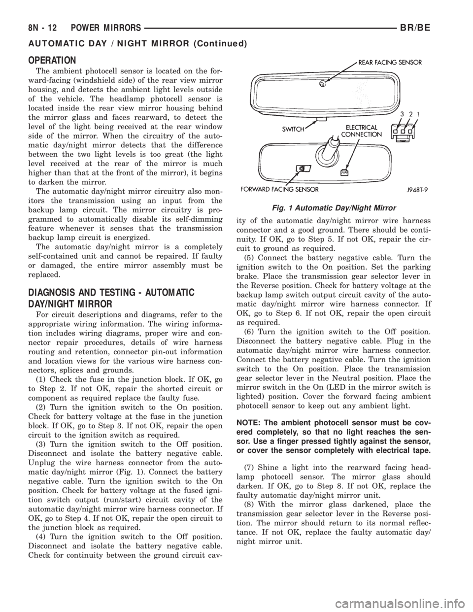
The ambient photocell sensor is located on the for-
ward-facing (windshield side) of the rear view mirror
housing, and detects the ambient light levels outside
of the vehicle. The headlamp photocell sensor is
located inside the rear view mirror housing behind
the mirror glass and faces rearward, to detect the
level of the light being received at the rear window
side of the mirror. When the circuitry of the auto-
matic day/night mirror detects that the difference
between the two light levels is too great (the light
level received at the rear of the mirror is much
higher than that at the front of the mirror), it begins
to darken the mirror.
The automatic day/night mirror circuitry also mon-
itors the transmission using an input from the
backup lamp circuit. The mirror circuitry is pro-
grammed to automatically disable its self-dimming
feature whenever it senses that the transmission
backup lamp circuit is energized.
The automatic day/night mirror is a completely
self-contained unit and cannot be repaired. If faulty
or damaged, the entire mirror assembly must be
replaced.
DIAGNOSIS AND TESTING - AUTOMATIC
DAY/NIGHT MIRROR
For circuit descriptions and diagrams, refer to the
appropriate wiring information. The wiring informa-
tion includes wiring diagrams, proper wire and con-
nector repair procedures, details of wire harness
routing and retention, connector pin-out information
and location views for the various wire harness con-
nectors, splices and grounds.
(1) Check the fuse in the junction block. If OK, go
to Step 2. If not OK, repair the shorted circuit or
component as required replace the faulty fuse.
(2) Turn the ignition switch to the On position.
Check for battery voltage at the fuse in the junction
block. If OK, go to Step 3. If not OK, repair the open
circuit to the ignition switch as required.
(3) Turn the ignition switch to the Off position.
Disconnect and isolate the battery negative cable.
Unplug the wire harness connector from the auto-
matic day/night mirror (Fig. 1). Connect the battery
negative cable. Turn the ignition switch to the On
position. Check for battery voltage at the fused igni-
tion switch output (run/start) circuit cavity of the
automatic day/night mirror wire harness connector. If
OK, go to Step 4. If not OK, repair the open circuit to
the junction block as required.
(4) Turn the ignition switch to the Off position.
Disconnect and isolate the battery negative cable.
Check for continuity between the ground circuit cav-ity of the automatic day/night mirror wire harness
connector and a good ground. There should be conti-
nuity. If OK, go to Step 5. If not OK, repair the cir-
cuit to ground as required.
(5) Connect the battery negative cable. Turn the
ignition switch to the On position. Set the parking
brake. Place the transmission gear selector lever in
the Reverse position. Check for battery voltage at the
backup lamp switch output circuit cavity of the auto-
matic day/night mirror wire harness connector. If
OK, go to Step 6. If not OK, repair the open circuit
as required.
(6) Turn the ignition switch to the Off position.
Disconnect the battery negative cable. Plug in the
automatic day/night mirror wire harness connector.
Connect the battery negative cable. Turn the ignition
switch to the On position. Place the transmission
gear selector lever in the Neutral position. Place the
mirror switch in the On (LED in the mirror switch is
lighted) position. Cover the forward facing ambient
photocell sensor to keep out any ambient light.
NOTE: The ambient photocell sensor must be cov-
ered completely, so that no light reaches the sen-
sor. Use a finger pressed tightly against the sensor,
or cover the sensor completely with electrical tape.
(7) Shine a light into the rearward facing head-
lamp photocell sensor. The mirror glass should
darken. If OK, go to Step 8. If not OK, replace the
faulty automatic day/night mirror unit.
(8) With the mirror glass darkened, place the
transmission gear selector lever in the Reverse posi-
tion. The mirror should return to its normal reflec-
tance. If not OK, replace the faulty automatic day/
night mirror unit.
Fig. 1 Automatic Day/Night Mirror
8N - 12 POWER MIRRORSBR/BE
AUTOMATIC DAY / NIGHT MIRROR (Continued)
Page 670 of 2255
WARNINGS - GENERAL
WARNINGSprovide information to prevent per-
sonal injury and vehicle damage. Below is a list of
general warnings that should be followed any time a
vehicle is being serviced.
WARNING:: ALWAYS WEAR SAFETY GLASSES FOR
EYE PROTECTION.
WARNING: USE SAFETY STANDS ANYTIME A PRO-
CEDURE REQUIRES BEING UNDER A VEHICLE.
WARNING: BE SURE THAT THE IGNITION SWITCH
ALWAYS IS IN THE OFF POSITION, UNLESS THE
PROCEDURE REQUIRES IT TO BE ON.
WARNING: SET THE PARKING BRAKE WHEN
WORKING ON ANY VEHICLE. AN AUTOMATIC
TRANSMISSION SHOULD BE IN PARK. A MANUAL
TRANSMISSION SHOULD BE IN NEUTRAL.
WARNING: OPERATE THE ENGINE ONLY IN A
WELL-VENTILATED AREA.
WARNING: KEEP AWAY FROM MOVING PARTS
WHEN THE ENGINE IS RUNNING, ESPECIALLY THE
FAN AND BELTS.
WARNING: TO PREVENT SERIOUS BURNS, AVOID
CONTACT WITH HOT PARTS SUCH AS THE RADIA-
TOR, EXHAUST MANIFOLD(S), TAIL PIPE, CATA-
LYTIC CONVERTER AND MUFFLER.
WARNING: DO NOT ALLOW FLAME OR SPARKS
NEAR THE BATTERY. GASES ARE ALWAYS
PRESENT IN AND AROUND THE BATTERY.
WARNING: ALWAYS REMOVE RINGS, WATCHES,
LOOSE HANGING JEWELRY AND AVOID LOOSE
CLOTHING.
DIAGNOSIS AND TESTING - WIRING HARNESS
TROUBLESHOOTING TOOLS
When diagnosing a problem in an electrical circuit
there are several common tools necessary. These tools
are listed and explained below.
²Jumper Wire - This is a test wire used to con-
nect two points of a circuit. It can be used to bypass
an open in a circuit.WARNING: NEVER USE A JUMPER WIRE ACROSS
A LOAD, SUCH AS A MOTOR, CONNECTED
BETWEEN A BATTERY FEED AND GROUND.
²Voltmeter - Used to check for voltage on a cir-
cuit. Always connect the black lead to a known good
ground and the red lead to the positive side of the
circuit.
CAUTION: Most of the electrical components used
in today's vehicles are Solid State. When checking
voltages in these circuits, use a meter with a 10 -
megohm or greater impedance rating.
²Ohmmeter - Used to check the resistance
between two points of a circuit. Low or no resistance
in a circuit means good continuity.
CAUTION: Most of the electrical components used
in today's vehicles are Solid State. When checking
resistance in these circuits use a meter with a 10 -
megohm or greater impedance rating. In addition,
make sure the power is disconnected from the cir-
cuit. Circuits that are powered up by the vehicle's
electrical system can cause damage to the equip-
ment and provide false readings.
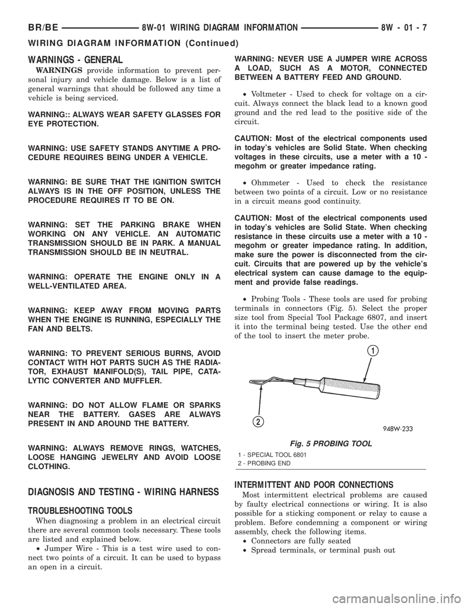
²Probing Tools - These tools are used for probing
terminals in connectors (Fig. 5). Select the proper
size tool from Special Tool Package 6807, and insert
it into the terminal being tested. Use the other end
of the tool to insert the meter probe.
INTERMITTENT AND POOR CONNECTIONS
Most intermittent electrical problems are caused
by faulty electrical connections or wiring. It is also
possible for a sticking component or relay to cause a
problem. Before condemning a component or wiring
assembly, check the following items.
²Connectors are fully seated
²Spread terminals, or terminal push out
Fig. 5 PROBING TOOL
1 - SPECIAL TOOL 6801
2 - PROBING END
BR/BE8W-01 WIRING DIAGRAM INFORMATION 8W - 01 - 7
WIRING DIAGRAM INFORMATION (Continued)
Page 1066 of 2255
tor between many of the engine compartment, instru-
ment panel, and body wire harnesses. The JB houses
up to nineteen blade-type fuses (two standard-type
and seventeen mini-type), up to two blade-type auto-
matic resetting circuit breakers, the electronic combi-
nation turn signal and hazard warning flasher, and
one International Standards Organization (ISO)
micro-relay.
The molded plastic JB housing has integral mount-
ing brackets that are secured with two screws to the
left instrument panel end bracket. The left end of the
instrument panel cover has a snap-fit fuse access
panel that can be removed for service of the JB. A
fuse puller and spare fuse holders are located on the
back of the fuse access cover, as well as an adhesive-
backed fuse layout map to ensure proper fuse identi-
fication.
The JB unit cannot be repaired and is only ser-
viced as an assembly. If any internal circuit or the JB
housing is faulty or damaged, the entire JB unit
must be replaced.
OPERATION
All of the circuits entering and leaving the JB do
so through up to nine wire harness connectors, which
are connected to the JB through integral connector
receptacles molded into the JB housing. Internal con-
nection of all of the JB circuits is accomplished by an
intricate combination of hard wiring and bus bars.
Refer toWiring Diagramsfor the location of com-
plete JB circuit diagrams.
DIAGNOSIS AND TESTING - JUNCTION BLOCK
The junction block does not incorporate any self
diagnostic capability. Most of the electrical circuits
incorporated into the vehicle must pass through the
junction block at one point or another. The most effi-
cient means of diagnosing a suspected junction block
problem involves a simple continuity tester or ohm
meter. Using the Wiring Diagrams as a guide trace
the problem circuit to the proper junction block cav-
ity and test all circuits in the effected circuit for
proper continuity. A open or high resistance circuit is
a sign of a problem. Some other possible junction
block problems to look for are:
²Loose fuse receptacle terminals.
²Loose relay / circuit breaker receptacle termi-
nals.
²Bent or distorted electrical circuit pins.
²Incorrect size fuse installed in junction block
fuse cavity.
²Dark areas identifying a source of excess heat.
²Defective fuse, relay or circuit breaker installed
in junction block cavity.
REMOVAL
(1) Disconnect and isolate the battery negative
cable.
(2) Remove the fuse access bezel from the instru-
ment panel.
(3) Remove the steering column cover (Refer to 23
- BODY/INSTRUMENT PANEL/STEERING COL-
UMN OPENING COVER - REMOVAL).
(4) Remove the hood release handle retaining
screws and position the handle assembly out of the
way.
(5) Remove the lower knee blocker from the instru-
ment panel.
(6) Pull drivers side carpet down, out of the way.
(7) Remove the parking brake switch connector,
release linkage and retaining fasteners and position
the assembly out the drivers door opening.
(8) Remove the electrical ground connections,
located behind park brake mounting location.
(9) Remove the two junction block retaining
screws. To access the upper retaining screw a 15 inch
long #2 Phillips screwdriver will be required. Access
the upper screw through hole in dash support brace.
(10) Reach through the outboard side of the instru-
ment panel steering column opening to access and
disconnect all of the wire harness connectors from
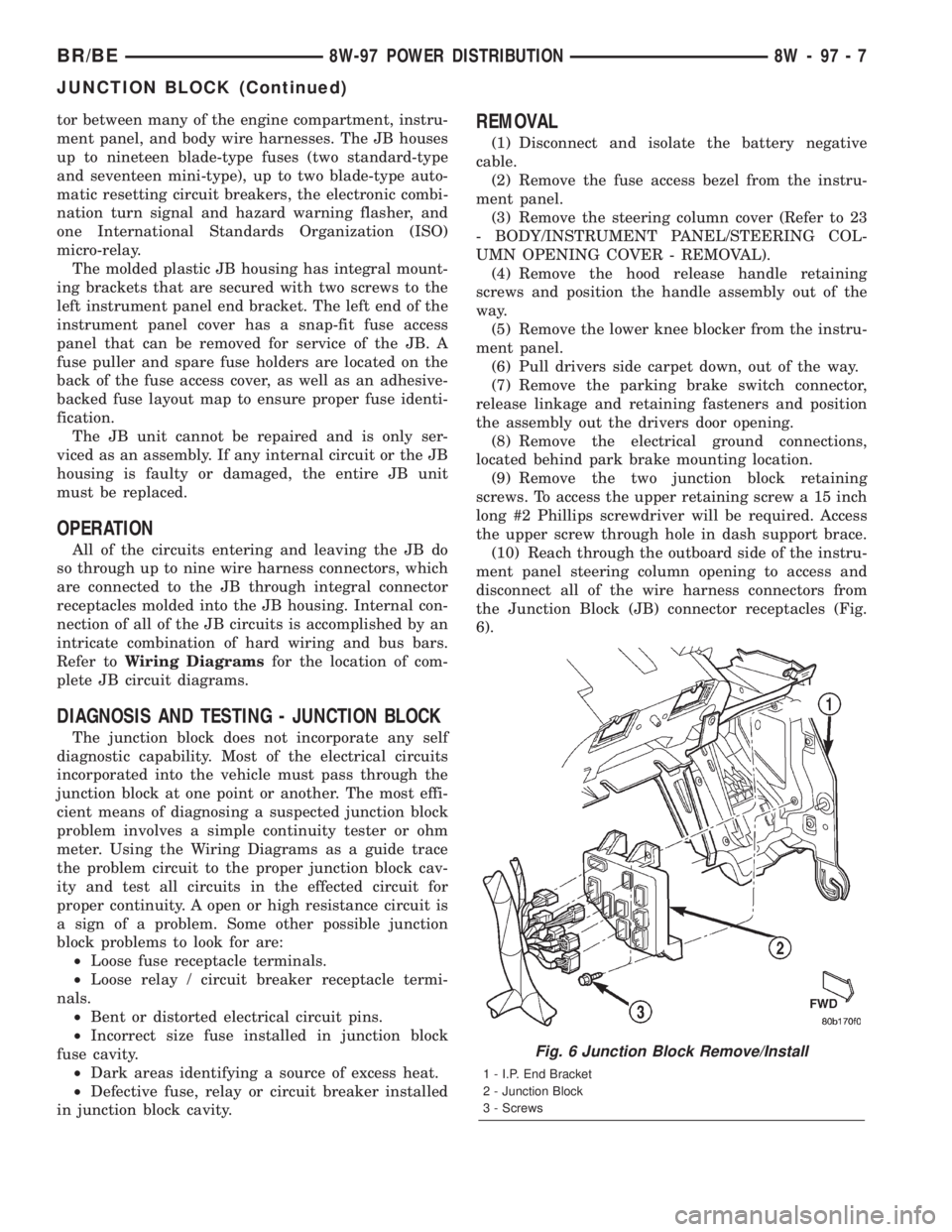
the Junction Block (JB) connector receptacles (Fig.
6).
Fig. 6 Junction Block Remove/Install
1 - I.P. End Bracket
2 - Junction Block
3 - Screws
BR/BE8W-97 POWER DISTRIBUTION 8W - 97 - 7
JUNCTION BLOCK (Continued)
Page 1067 of 2255
(11) Remove the junction block from under the
instrument panel.
INSTALLATION
NOTE: If the Junction Block (JB) is being replaced
with a new unit, be certain to transfer each of the
fuses, circuit breakers and relays from the faulty JB
to the proper cavities of the replacement JB. Refer
to Junction Block in the index of this service man-
ual for the location of complete circuit diagrams
and cavity assignments for the JB.
(1) Position the junction block under the instru-
ment panel.
(2) Connect all of the wire harness connectors on
the Junction Block (JB) connector receptacles.
(3) Install the two junction block retaining screws.
(4) Install the electrical ground connections,
located behind park brake mounting location.
(5) Install the parking brake switch connector,
release linkage and retaining fasteners.
(6) Reposition drivers side carpet.
(7) Install the lower knee blocker on the instru-
ment panel.
(8) Install the hood release handle retaining
screws.
(9) Install the steering column cover.
(10) Install the fuse access bezel on the instrument
panel.
(11) Connect the battery negative cable.
POWER DISTRIBUTION
CENTER
DESCRIPTION
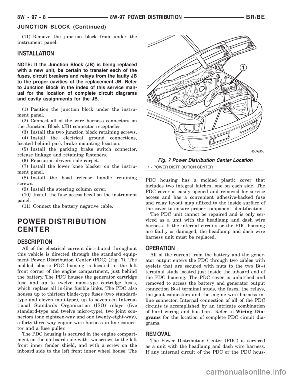
All of the electrical current distributed throughout
this vehicle is directed through the standard equip-
ment Power Distribution Center (PDC) (Fig. 7). The
molded plastic PDC housing is located in the left
front corner of the engine compartment, just behind
the battery. The PDC houses the generator cartridge
fuse and up to twelve maxi-type cartridge fuses,
which replace all in-line fusible links. The PDC also
houses up to thirteen blade-type fuses (two standard-
type and eleven mini-type), up to seventeen Interna-
tional Standards Organization (ISO) relays (five
standard-type and twelve micro-type), two joint con-
nectors (one eighteen-way and one twenty-eight-way),
a forty-three-way engine wire harness in-line connec-
tor and a fuse puller.
The PDC housing is secured in the engine compart-
ment on the outboard side with two screws to the left
front inner fender shield, and with a screw on the
inboard side to the left front inner wheel house. ThePDC housing has a molded plastic cover that
includes two integral latches, one on each side. The
PDC cover is easily opened and removed for service
access and has a convenient adhesive-backed fuse
and relay layout map affixed to the inside surface of
the cover to ensure proper component identification.
The PDC unit cannot be repaired and is only ser-
viced as a unit with the headlamp and dash wire
harness. If the internal circuits or the PDC housing
are faulty or damaged, the headlamp and dash wire
harness unit must be replaced.OPERATION
All of the current from the battery and the gener-
ator output enters the PDC through two cables with
eyelets that are secured with nuts to the two B(+)
terminal studs located just inside the inboard end of
the PDC housing. The PDC cover is unlatched and
removed to access the battery and generator output
connection B(+) terminal studs, the fuses, the relays,
the joint connectors and the engine wire harness in-
line connector. Internal connection of all of the PDC
circuits is accomplished by an intricate combination
of hard wiring and bus bars. Refer toWiring Dia-
gramsfor the location of complete PDC circuit dia-
grams.
REMOVAL
The Power Distribution Center (PDC) is serviced
as a unit with the headlamp and dash wire harness.
If any internal circuit of the PDC or the PDC hous-
Fig. 7 Power Distribution Center Location
1 - POWER DISTRIBUTION CENTER
8W - 97 - 8 8W-97 POWER DISTRIBUTIONBR/BE
JUNCTION BLOCK (Continued)
Page 1611 of 2255
In either case, air bubbles can cause overheating
and/or fluid oxidation, and varnishing. This can
interfere with normal valve, clutch, and accumulator
operation. Foaming can also result in fluid escaping
from the transmission vent where it may be mis-
taken for a leak.
Along with fluid level, it is important to check the
condition of the fluid. When the fluid smells burned,
and is contaminated with metal or friction material
particles, a complete transmission recondition is
needed. Be sure to examine the fluid on the dipstick
closely. If there is any doubt about its condition,
drain out a sample for a double check.
After the fluid has been checked, seat the dipstick
fully to seal out water and dirt.
The transmission has a dipstick to check oil level.
It is located on the right side of the engine. Be sure
to wipe all dirt from dipstick handle before removing.
Fluid level is checked with the engine running at
curb idle speed, the transmission in NEUTRAL and
the transmission fluid at normal operating tempera-
ture.The engine should be running at idle
speed for at least one minute, with the vehicle
on level ground.
The transmission fluid level can be checked two
ways.
PROCEDURE ONE
(1) Transmission fluid must be at normal operat-
ing temperature for accurate fluid level check. Drive
vehicle if necessary to bring fluid temperature up to
normal hot operating temperature of 82ÉC (180ÉF).
(2) Position vehicle on level surface.
(3) Start and run engine at curb idle speed.
(4) Apply parking brakes.
(5) Shift transmission momentarily into all gear
ranges. Then shift transmission back to NEUTRAL.
(6) Clean top of filler tube and dipstick to keep
dirt from entering tube.
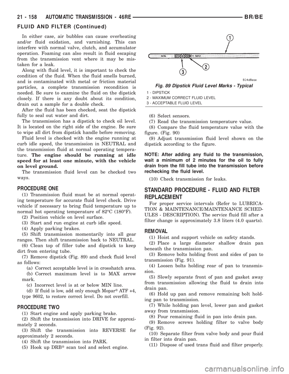
(7) Remove dipstick (Fig. 89) and check fluid level
as follows:
(a) Correct acceptable level is in crosshatch area.
(b) Correct maximum level is to MAX arrow
mark.
(c) Incorrect level is at or below MIN line.
(d)
If fluid is low, add only enough MopartATF +4,
type 9602, to restore correct level. Do not overfill.
PROCEDURE TWO
(1) Start engine and apply parking brake.
(2) Shift the transmission into DRIVE for approxi-
mately 2 seconds.
(3) Shift the transmission into REVERSE for
approximately 2 seconds.
(4) Shift the transmission into PARK.
(5) Hook up DRBtscan tool and select engine.(6) Select sensors.
(7) Read the transmission temperature value.
(8) Compare the fluid temperature value with the
figure. (Fig. 90)
(9) Adjust transmission fluid level shown on the
dipstick according to the figure.
NOTE: After adding any fluid to the transmission,
wait a minimum of 2 minutes for the oil to fully
drain from the fill tube into the transmission before
rechecking the fluid level.
(10) Check transmission for leaks.
STANDARD PROCEDURE - FLUID AND FILTER
REPLACEMENT
For proper service intervals (Refer to LUBRICA-
TION & MAINTENANCE/MAINTENANCE SCHED-
ULES - DESCRIPTION). The service fluid fill after a
filter change is approximately 3.8 liters (4.0 quarts).
REMOVAL
(1) Hoist and support vehicle on safety stands.
(2) Place a large diameter shallow drain pan
beneath the transmission pan.
(3) Remove bolts holding front and sides of pan to
transmission (Fig. 91).
(4) Loosen bolts holding rear of pan to transmis-
sion.
(5) Slowly separate front of pan and gasket away
from transmission allowing the fluid to drain into
drain pan.
(6) Hold up pan and remove remaining bolt hold-
ing pan to transmission.
(7) While holding pan level, lower pan and gasket
away from transmission.
(8) Pour remaining fluid in pan into drain pan.
(9) Remove screws holding filter to valve body
(Fig. 92).
(10) Separate filter from valve body and pour fluid
in filter into drain pan.
(11) Dispose of used trans fluid and filter properly.
Fig. 89 Dipstick Fluid Level Marks - Typical
1 - DIPSTICK
2 - MAXIMUM CORRECT FLUID LEVEL
3 - ACCEPTABLE FLUID LEVEL
21 - 158 AUTOMATIC TRANSMISSION - 46REBR/BE
FLUID AND FILTER (Continued)
Page 1613 of 2255
INSTALLATION
(1) Position a new transmission oil filter onto the
valve body.
(2) Install the screws to hold the filter to the valve
body. Tighten the screws to 4 N´m (35 in.lbs.).
(3) Clean the gasket surfaces of the transmission
oil pan and transmission pan rail.
NOTE: The transmission pan oil gasket is reusable.
Inspect the sealing surfaces of the gasket. If the
sealing ribs on both surfaces appear to be in good
condition, clean the gasket of any foreign material
and reinstall.
(4) Position the oil pan gasket onto the oil pan.
(5) Position the oil pan and gasket onto the trans-
mission and install several bolts to hold the pan and
gasket to the transmission.
(6) Install the remainder of the oil pan bolts.
Tighten the bolts to 13.6 N´m (125 in.lbs.).
(7) Lower vehicle and fill transmission. (Refer to
21 - TRANSMISSION/TRANSAXLE/AUTOMATIC/
FLUID - STANDARD PROCEDURE)
STANDARD PROCEDURE - TRANSMISSION
FILL
To avoid overfilling transmission after a fluid
change or overhaul, perform the following procedure:
(1) Remove dipstick and insert clean funnel in
transmission fill tube.
(2) Add following initial quantity of MopartAT F
+4, type 9602, to transmission:
(a) If only fluid and filter were changed, add3
pints (1-1/2 quarts)of ATF +4 to transmission.
(b) If transmission was completely overhauled,
torque converter was replaced or drained, and
cooler was flushed, add12 pints (6 quarts)of ATF
+4 to transmission.
(3) Apply parking brakes.
(4) Start and run engine at normal curb idle
speed.
(5) Apply service brakes, shift transmission
through all gear ranges then back to NEUTRAL, set
parking brake, and leave engine running at curb idle
speed.
(6) Remove funnel, insert dipstick and check fluid
level. If level is low,add fluid to bring level to
MIN mark on dipstick.Check to see if the oil level
is equal on both sides of the dipstick. If one side is
noticably higher than the other, the dipstick has
picked up some oil from the dipstick tube. Allow the
oil to drain down the dipstick tube and re-check.
(7) Drive vehicle until transmission fluid is at nor-
mal operating temperature.(8) With the engine running at curb idle speed, the
gear selector in NEUTRAL, and the parking brake
applied, check the transmission fluid level.
CAUTION: Do not overfill transmission, fluid foam-
ing and shifting problems can result.
(9) Add fluid to bring level up to MAX arrow
mark.
When fluid level is correct, shut engine off, release
park brake, remove funnel, and install dipstick in fill
tube.
FRONT CLUTCH
DESCRIPTION
The front clutch assembly (Fig. 93) is composed of
the front clutch retainer, pressure plate, clutch
plates, driving discs, piston, piston return spring,
return spring retainer, and snap-rings. The front
clutch is the forward-most component in the trans-
mission geartrain and is directly behind the oil pump
and is considered a driving component.
NOTE: The number of discs and plates may vary
with each engine and vehicle combination.
OPERATION
To apply the clutch, pressure is applied between
the clutch retainer and piston. The fluid pressure is
provided by the oil pump, transferred through the
control valves and passageways, and enters the
clutch through the hub of the reaction shaft support.
With pressure applied between the clutch retainer
and piston, the piston moves away from the clutch
retainer and compresses the clutch pack. This action
applies the clutch pack, allowing torque to flow
through the input shaft into the driving discs, and
into the clutch plates and pressure plate that are
lugged to the clutch retainer. The waved snap-ring is
used to cushion the application of the clutch pack.
When pressure is released from the piston, the
spring returns the piston to its fully released position
and disengages the clutch. The release spring also
helps to cushion the application of the clutch assem-
bly. When the clutch is in the process of being
released by the release spring, fluid flows through a
vent and one-way ball-check-valve located in the
clutch retainer. The check-valve is needed to elimi-
nate the possibility of plate drag caused by centrifu-
gal force acting on the residual fluid trapped in the
clutch piston retainer.
21 - 160 AUTOMATIC TRANSMISSION - 46REBR/BE
FLUID AND FILTER (Continued)
Page 1781 of 2255
sludge and/or debris. The torque converter should
also be replaced at the same time.
Failure to flush the cooler and lines will result in
recontamination. Flushing applies to auxiliary cool-
ers as well. The torque converter should also be
replaced whenever a failure generates sludge and
debris. This is necessary because normal converter
flushing procedures will not remove all contami-
nants.
STANDARD PROCEDURE
STANDARD PROCEDURE - FLUID LEVEL
CHECK
Low fluid level can cause a variety of conditions
because it allows the pump to take in air along with
the fluid. As in any hydraulic system, air bubbles
make the fluid spongy, therefore, pressures will be
low and build up slowly.
Improper filling can also raise the fluid level too
high. When the transmssion has too much fluid, the
geartrain churns up foam and cause the same condi-
tions which occur with a low fluid level.
In either case, air bubbles can cause overheating
and/or fluid oxidation, and varnishing. This can
interfere with normal valve, clutch, and accumulator
operation. Foaming can also result in fluid escaping
from the transmission vent where it may be mis-
taken for a leak.
Along with fluid level, it is important to check the
condition of the fluid. When the fluid smells burned,
and is contaminated with metal or friction material
particles, a complete transmission recondition is
needed. Be sure to examine the fluid on the dipstick
closely. If there is any doubt about its condition,
drain out a sample for a double check.
After the fluid has been checked, seat the dipstick
fully to seal out water and dirt.
The transmission has a dipstick to check oil level.
It is located on the right side of the engine. Be sure
to wipe all dirt from dipstick handle before removing.
Fluid level is checked with the engine running at
curb idle speed, the transmission in NEUTRAL and
the transmission fluid at normal operating tempera-
ture.The engine should be running at idle
speed for at least one minute, with the vehicle
on level ground.
The transmission fluid level can be checked two
ways.
PROCEDURE ONE
(1) Transmission fluid must be at normal operat-
ing temperature for accurate fluid level check. Drive
vehicle if necessary to bring fluid temperature up to
normal hot operating temperature of 82ÉC (180ÉF).(2) Position vehicle on level surface.
(3) Start and run engine at curb idle speed.
(4) Apply parking brakes.
(5) Shift transmission momentarily into all gear
ranges. Then shift transmission back to NEUTRAL.
(6) Clean top of filler tube and dipstick to keep
dirt from entering tube.
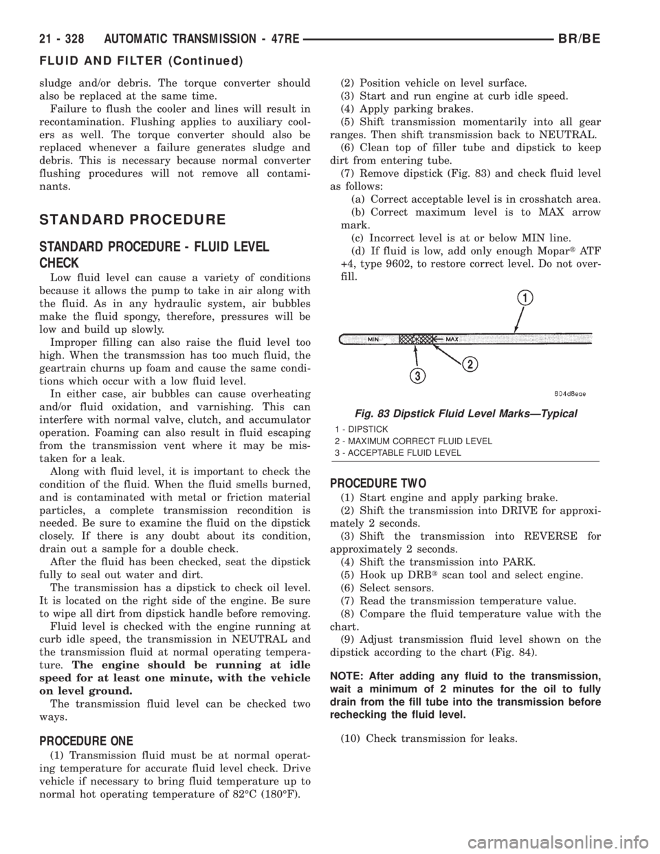
(7) Remove dipstick (Fig. 83) and check fluid level
as follows:
(a) Correct acceptable level is in crosshatch area.
(b) Correct maximum level is to MAX arrow
mark.
(c) Incorrect level is at or below MIN line.
(d) If fluid is low, add only enough MopartAT F
+4, type 9602, to restore correct level. Do not over-
fill.
PROCEDURE TWO
(1) Start engine and apply parking brake.
(2) Shift the transmission into DRIVE for approxi-
mately 2 seconds.
(3) Shift the transmission into REVERSE for
approximately 2 seconds.
(4) Shift the transmission into PARK.
(5) Hook up DRBtscan tool and select engine.
(6) Select sensors.
(7) Read the transmission temperature value.
(8) Compare the fluid temperature value with the
chart.
(9) Adjust transmission fluid level shown on the
dipstick according to the chart (Fig. 84).
NOTE: After adding any fluid to the transmission,
wait a minimum of 2 minutes for the oil to fully
drain from the fill tube into the transmission before
rechecking the fluid level.
(10) Check transmission for leaks.
Fig. 83 Dipstick Fluid Level MarksÐTypical
1 - DIPSTICK
2 - MAXIMUM CORRECT FLUID LEVEL
3 - ACCEPTABLE FLUID LEVEL
21 - 328 AUTOMATIC TRANSMISSION - 47REBR/BE
FLUID AND FILTER (Continued)
Page 1783 of 2255
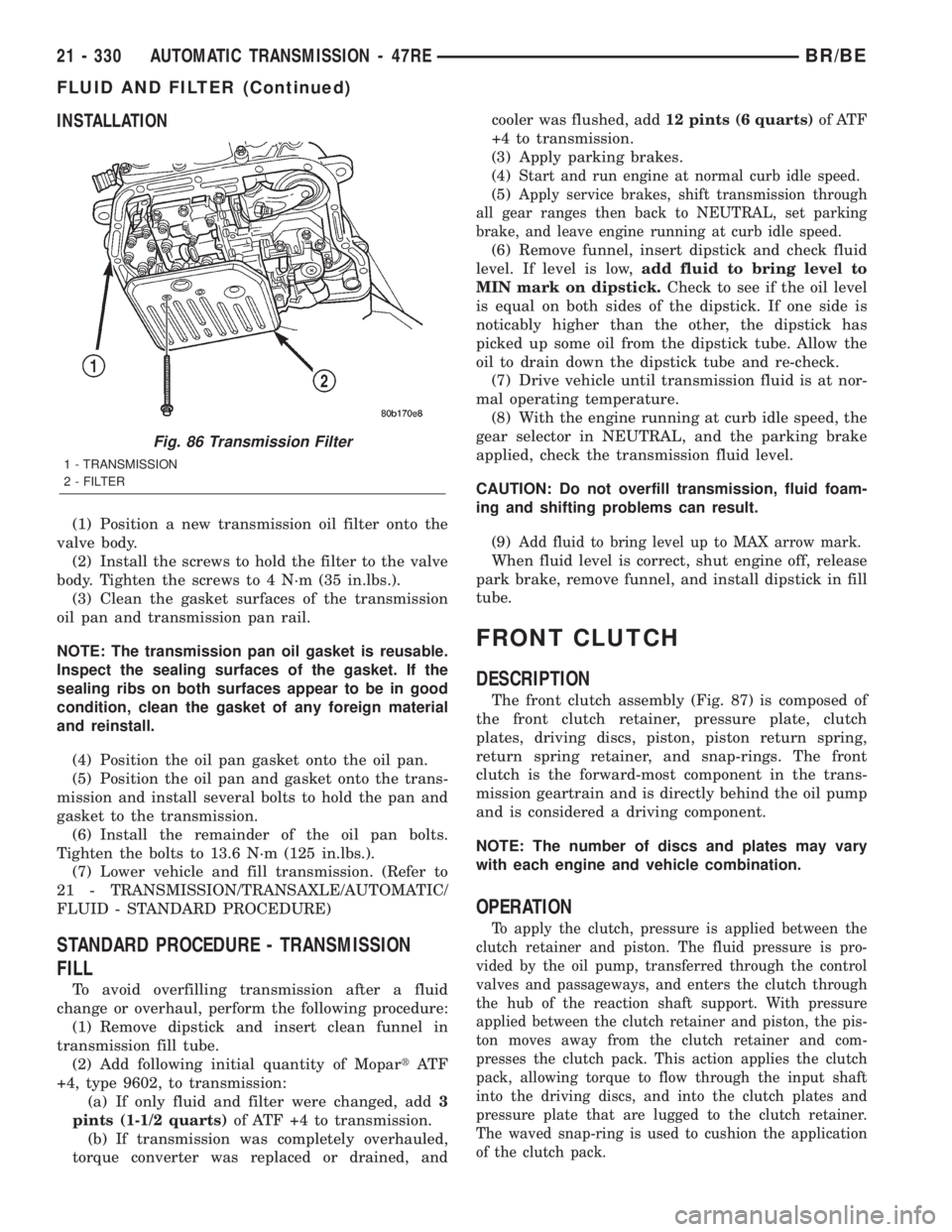
INSTALLATION
(1) Position a new transmission oil filter onto the
valve body.
(2) Install the screws to hold the filter to the valve
body. Tighten the screws to 4 N´m (35 in.lbs.).
(3) Clean the gasket surfaces of the transmission
oil pan and transmission pan rail.
NOTE: The transmission pan oil gasket is reusable.
Inspect the sealing surfaces of the gasket. If the
sealing ribs on both surfaces appear to be in good
condition, clean the gasket of any foreign material
and reinstall.
(4) Position the oil pan gasket onto the oil pan.
(5) Position the oil pan and gasket onto the trans-
mission and install several bolts to hold the pan and
gasket to the transmission.
(6) Install the remainder of the oil pan bolts.
Tighten the bolts to 13.6 N´m (125 in.lbs.).
(7) Lower vehicle and fill transmission. (Refer to
21 - TRANSMISSION/TRANSAXLE/AUTOMATIC/
FLUID - STANDARD PROCEDURE)
STANDARD PROCEDURE - TRANSMISSION
FILL
To avoid overfilling transmission after a fluid
change or overhaul, perform the following procedure:
(1) Remove dipstick and insert clean funnel in
transmission fill tube.
(2) Add following initial quantity of MopartAT F
+4, type 9602, to transmission:
(a) If only fluid and filter were changed, add3
pints (1-1/2 quarts)of ATF +4 to transmission.
(b) If transmission was completely overhauled,
torque converter was replaced or drained, andcooler was flushed, add12 pints (6 quarts)of ATF
+4 to transmission.
(3) Apply parking brakes.
(4)
Start and run engine at normal curb idle speed.
(5)Apply service brakes, shift transmission through
all gear ranges then back to NEUTRAL, set parking
brake, and leave engine running at curb idle speed.
(6) Remove funnel, insert dipstick and check fluid
level. If level is low,add fluid to bring level to
MIN mark on dipstick.Check to see if the oil level
is equal on both sides of the dipstick. If one side is
noticably higher than the other, the dipstick has
picked up some oil from the dipstick tube. Allow the
oil to drain down the dipstick tube and re-check.
(7) Drive vehicle until transmission fluid is at nor-
mal operating temperature.
(8) With the engine running at curb idle speed, the
gear selector in NEUTRAL, and the parking brake
applied, check the transmission fluid level.
CAUTION: Do not overfill transmission, fluid foam-
ing and shifting problems can result.
(9)
Add fluid to bring level up to MAX arrow mark.
When fluid level is correct, shut engine off, release
park brake, remove funnel, and install dipstick in fill
tube.
FRONT CLUTCH
DESCRIPTION
The front clutch assembly (Fig. 87) is composed of
the front clutch retainer, pressure plate, clutch
plates, driving discs, piston, piston return spring,
return spring retainer, and snap-rings. The front
clutch is the forward-most component in the trans-
mission geartrain and is directly behind the oil pump
and is considered a driving component.
NOTE: The number of discs and plates may vary
with each engine and vehicle combination.
OPERATION
To apply the clutch, pressure is applied between the
clutch retainer and piston. The fluid pressure is pro-
vided by the oil pump, transferred through the control
valves and passageways, and enters the clutch through
the hub of the reaction shaft support. With pressure
applied between the clutch retainer and piston, the pis-
ton moves away from the clutch retainer and com-
presses the clutch pack. This action applies the clutch
pack, allowing torque to flow through the input shaft
into the driving discs, and into the clutch plates and
pressure plate that are lugged to the clutch retainer.
The waved snap-ring is used to cushion the application
of the clutch pack.
Fig. 86 Transmission Filter
1 - TRANSMISSION
2 - FILTER
21 - 330 AUTOMATIC TRANSMISSION - 47REBR/BE
FLUID AND FILTER (Continued)
Page 2075 of 2255
CLUSTER BEZEL
REMOVAL
WARNING: ON VEHICLES EQUIPPED WITH AIR-
BAGS, DISABLE THE AIRBAG SYSTEM BEFORE
ATTEMPTING ANY STEERING WHEEL, STEERING
COLUMN, SEAT BELT TENSIONER, OR INSTRU-
MENT PANEL COMPONENT DIAGNOSIS OR SER-
VICE. DISCONNECT AND ISOLATE THE BATTERY
NEGATIVE (GROUND) CABLE, THEN WAIT TWO
MINUTES FOR THE AIRBAG SYSTEM CAPACITOR
TO DISCHARGE BEFORE PERFORMING FURTHER
DIAGNOSIS OR SERVICE. THIS IS THE ONLY SURE
WAY TO DISABLE THE AIRBAG SYSTEM. FAILURE
TO TAKE THE PROPER PRECAUTIONS COULD
RESULT IN ACCIDENTAL AIRBAG DEPLOYMENT
AND POSSIBLE PERSONAL INJURY.
(1) Disconnect and isolate the battery negative
cable.
(2) If the vehicle is equipped with an automatic
transmission, turn the ignition switch to the Off posi-
tion (not Lock), set the parking brake, and place the
automatic transmission gear selector lever in the
Low position.
(3) If the vehicle is so equipped, set the tilt steer-
ing column in its lowest position.
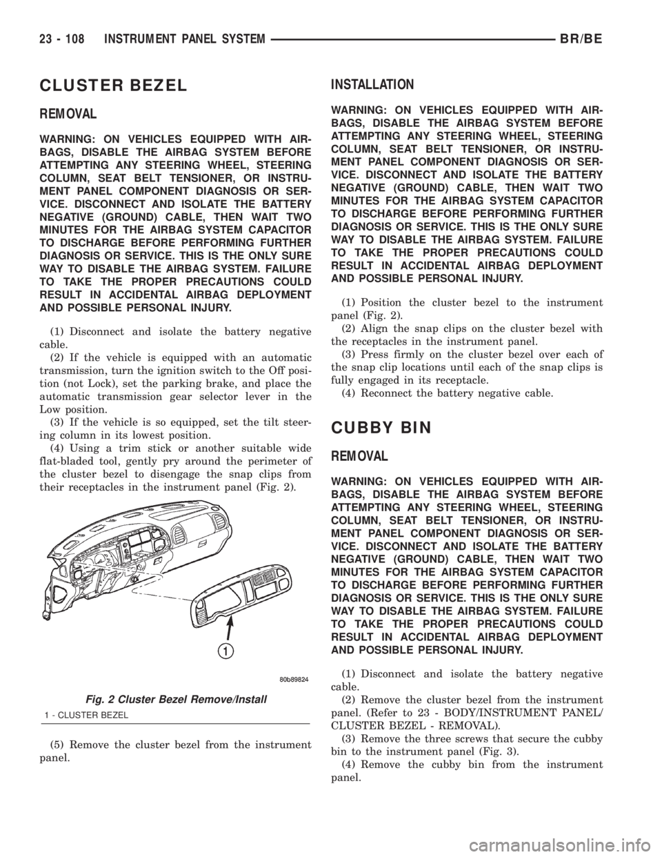
(4) Using a trim stick or another suitable wide
flat-bladed tool, gently pry around the perimeter of
the cluster bezel to disengage the snap clips from
their receptacles in the instrument panel (Fig. 2).
(5) Remove the cluster bezel from the instrument
panel.
INSTALLATION
WARNING: ON VEHICLES EQUIPPED WITH AIR-
BAGS, DISABLE THE AIRBAG SYSTEM BEFORE
ATTEMPTING ANY STEERING WHEEL, STEERING
COLUMN, SEAT BELT TENSIONER, OR INSTRU-
MENT PANEL COMPONENT DIAGNOSIS OR SER-
VICE. DISCONNECT AND ISOLATE THE BATTERY
NEGATIVE (GROUND) CABLE, THEN WAIT TWO
MINUTES FOR THE AIRBAG SYSTEM CAPACITOR
TO DISCHARGE BEFORE PERFORMING FURTHER
DIAGNOSIS OR SERVICE. THIS IS THE ONLY SURE
WAY TO DISABLE THE AIRBAG SYSTEM. FAILURE
TO TAKE THE PROPER PRECAUTIONS COULD
RESULT IN ACCIDENTAL AIRBAG DEPLOYMENT
AND POSSIBLE PERSONAL INJURY.
(1) Position the cluster bezel to the instrument
panel (Fig. 2).
(2) Align the snap clips on the cluster bezel with
the receptacles in the instrument panel.
(3) Press firmly on the cluster bezel over each of
the snap clip locations until each of the snap clips is
fully engaged in its receptacle.
(4) Reconnect the battery negative cable.
CUBBY BIN
REMOVAL
WARNING: ON VEHICLES EQUIPPED WITH AIR-
BAGS, DISABLE THE AIRBAG SYSTEM BEFORE
ATTEMPTING ANY STEERING WHEEL, STEERING
COLUMN, SEAT BELT TENSIONER, OR INSTRU-
MENT PANEL COMPONENT DIAGNOSIS OR SER-
VICE. DISCONNECT AND ISOLATE THE BATTERY
NEGATIVE (GROUND) CABLE, THEN WAIT TWO
MINUTES FOR THE AIRBAG SYSTEM CAPACITOR
TO DISCHARGE BEFORE PERFORMING FURTHER
DIAGNOSIS OR SERVICE. THIS IS THE ONLY SURE
WAY TO DISABLE THE AIRBAG SYSTEM. FAILURE
TO TAKE THE PROPER PRECAUTIONS COULD
RESULT IN ACCIDENTAL AIRBAG DEPLOYMENT
AND POSSIBLE PERSONAL INJURY.
(1) Disconnect and isolate the battery negative
cable.
(2) Remove the cluster bezel from the instrument
panel. (Refer to 23 - BODY/INSTRUMENT PANEL/
CLUSTER BEZEL - REMOVAL).
(3) Remove the three screws that secure the cubby
bin to the instrument panel (Fig. 3).
(4) Remove the cubby bin from the instrument
panel.
Fig. 2 Cluster Bezel Remove/Install
1 - CLUSTER BEZEL
23 - 108 INSTRUMENT PANEL SYSTEMBR/BE