heating DODGE RAM 2002 Service Repair Manual
[x] Cancel search | Manufacturer: DODGE, Model Year: 2002, Model line: RAM, Model: DODGE RAM 2002Pages: 2255, PDF Size: 62.07 MB
Page 1 of 2255
GROUP TAB LOCATOR
Introduction
0Lubrication & Maintenance
2Suspension
3Differential & Driveline
5Brakes
6Clutch
7Cooling
8AAudio
8BChime/Buzzer
8EElectronic Control Modules
8FEngine Systems
8GHeated Systems
8HHorn
8IIgnition Control
8JInstrument Cluster
8LLamps
8MMessage Systems
8NPower Systems
8ORestraints
8PSpeed Control
8QVehicle Theft Security
8RWipers/Washers
8WWiring
9Engine
11Exhaust System
13Frame & Bumpers
14Fuel System
19Steering
21Transmission and Transfer Case
22Tires/Wheels
23Body
24Heating & Air Conditioning
25Emissions Control
Component and System Index
Service Manual Comment Forms (Rear of Manual)
NOTE: For New Vehicle Preparation
information, see the separate
publication, 81-170-00003.
Page 19 of 2255
DESCRIPTION - AUTOMATIC TRANSMISSION
FLUID
NOTE: Refer to the maintenance schedules in this
group for the recommended maintenance (fluid/filter
change) intervals for this transmission.
NOTE: Refer to Service Procedures in this group for
fluid level checking procedures.
MopartATF +4, type 9602, Automatic Transmis-
sion Fluid is the recommended fluid for
DaimlerChrysler automatic transmissions.
Dexron II fluid IS NOT recommended. Clutch
chatter can result from the use of improper
fluid.
MopartATF +4, type 9602, Automatic Transmis-
sion Fluid when new is red in color. The ATF is dyed
red so it can be identified from other fluids used in
the vehicle such as engine oil or antifreeze. The red
color is not permanent and is not an indicator of fluid
condition. As the vehicle is driven, the ATF will begin
to look darker in color and may eventually become
brown.This is normal.A dark brown/black fluid
accompanied with a burnt odor and/or deterioration
in shift quality may indicate fluid deterioration or
transmission component failure.
FLUID ADDITIVES
DaimlerChrysler strongly recommends against the
addition of any fluids to the transmission, other than
those automatic transmission fluids listed above.
Exceptions to this policy are the use of special dyes
to aid in detecting fluid leaks.
Various ªspecialº additives and supplements exist
that claim to improve shift feel and/or quality. These
additives and others also claim to improve converter
clutch operation and inhibit overheating, oxidation,
varnish, and sludge. These claims have not been sup-
ported to the satisfaction of DaimlerChrysler and
these additivesmust not be used.The use of trans-
mission ªsealersº should also be avoided, since they
may adversely affect the integrity of transmission
seals.
OPERATION - AUTOMATIC TRANSMISSION
FLUID
The automatic transmission fluid is selected based
upon several qualities. The fluid must provide a high
level of protection for the internal components by
providing a lubricating film between adjacent metal
components. The fluid must also be thermally stable
so that it can maintain a consistent viscosity through
a large temperature range. If the viscosity stays con-
stant through the temperature range of operation,transmission operation and shift feel will remain con-
sistent. Transmission fluid must also be a good con-
ductor of heat. The fluid must absorb heat from the
internal transmission components and transfer that
heat to the transmission case.
FLUID CAPACITIES
SPECIFICATIONS
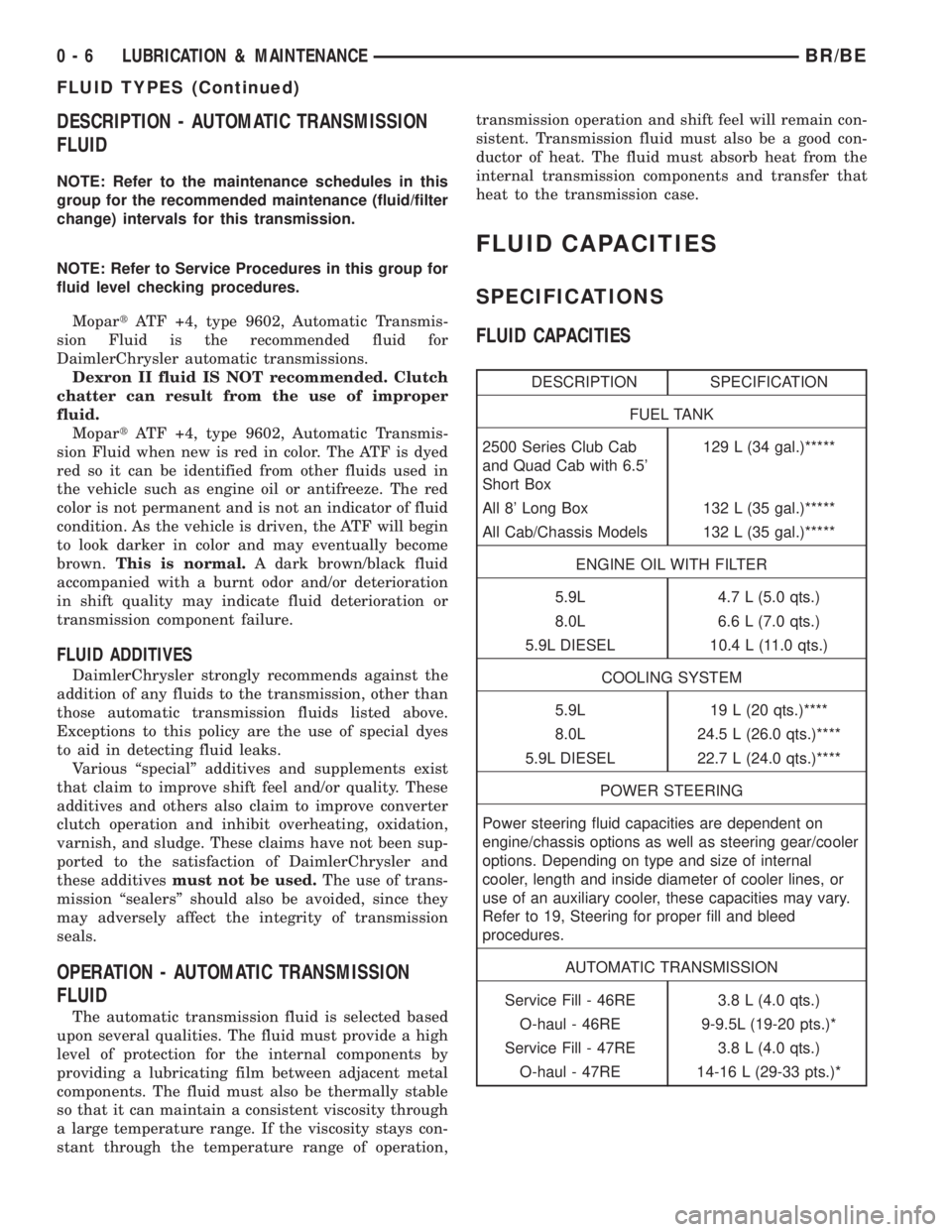
FLUID CAPACITIES
DESCRIPTION SPECIFICATION
FUEL TANK
2500 Series Club Cab
and Quad Cab with 6.5'
Short Box129 L (34 gal.)*****
All 8' Long Box 132 L (35 gal.)*****
All Cab/Chassis Models 132 L (35 gal.)*****
ENGINE OIL WITH FILTER
5.9L 4.7 L (5.0 qts.)
8.0L 6.6 L (7.0 qts.)
5.9L DIESEL 10.4 L (11.0 qts.)
COOLING SYSTEM
5.9L 19 L (20 qts.)****
8.0L 24.5 L (26.0 qts.)****
5.9L DIESEL 22.7 L (24.0 qts.)****
POWER STEERING
Power steering fluid capacities are dependent on
engine/chassis options as well as steering gear/cooler
options. Depending on type and size of internal
cooler, length and inside diameter of cooler lines, or
use of an auxiliary cooler, these capacities may vary.
Refer to 19, Steering for proper fill and bleed
procedures.
AUTOMATIC TRANSMISSION
Service Fill - 46RE 3.8 L (4.0 qts.)
O-haul - 46RE 9-9.5L (19-20 pts.)*
Service Fill - 47RE 3.8 L (4.0 qts.)
O-haul - 47RE 14-16 L (29-33 pts.)*
0 - 6 LUBRICATION & MAINTENANCEBR/BE
FLUID TYPES (Continued)
Page 26 of 2255
SUSPENSION
TABLE OF CONTENTS
page page
WHEEL ALIGNMENT......................1
FRONT - 2WD............................7FRONT - 4WD...........................14
REAR.................................25
WHEEL ALIGNMENT
TABLE OF CONTENTS
page page
WHEEL ALIGNMENT
DESCRIPTION..........................1
OPERATION............................2
DIAGNOSIS AND TESTING - PRE-ALIGNMENT . 2
STANDARD PROCEDURE
STANDARD PROCEDURES - ALIGNMENT
I.F.S. ................................3STANDARD PROCEDURE - CASTER
CORRECTION MEASUREMENT...........3
STANDARD PROCEDURE - ALIGNMENT
LINK/COIL SUSPENSION.................5
SPECIFICATIONS
ALIGNMENT..........................6
WHEEL ALIGNMENT
DESCRIPTION
Wheel alignment is the positioning of the wheels in
relation to the vehicle. This is accomplished through
suspension and steering linkage adjustments. An
alignment is essential for efficient steering, good
directional stability and to minimize tire wear. The
most important measurements of an alignment are
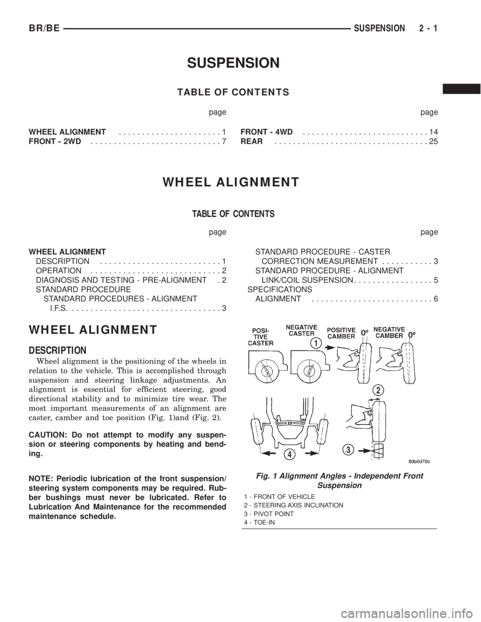
caster, camber and toe position (Fig. 1)and (Fig. 2).
CAUTION: Do not attempt to modify any suspen-
sion or steering components by heating and bend-
ing.
NOTE: Periodic lubrication of the front suspension/
steering system components may be required. Rub-
ber bushings must never be lubricated. Refer to
Lubrication And Maintenance for the recommended
maintenance schedule.
Fig. 1 Alignment Angles - Independent Front
Suspension
1 - FRONT OF VEHICLE
2 - STEERING AXIS INCLINATION
3 - PIVOT POINT
4 - TOE-IN
BR/BESUSPENSION 2 - 1
Page 72 of 2255
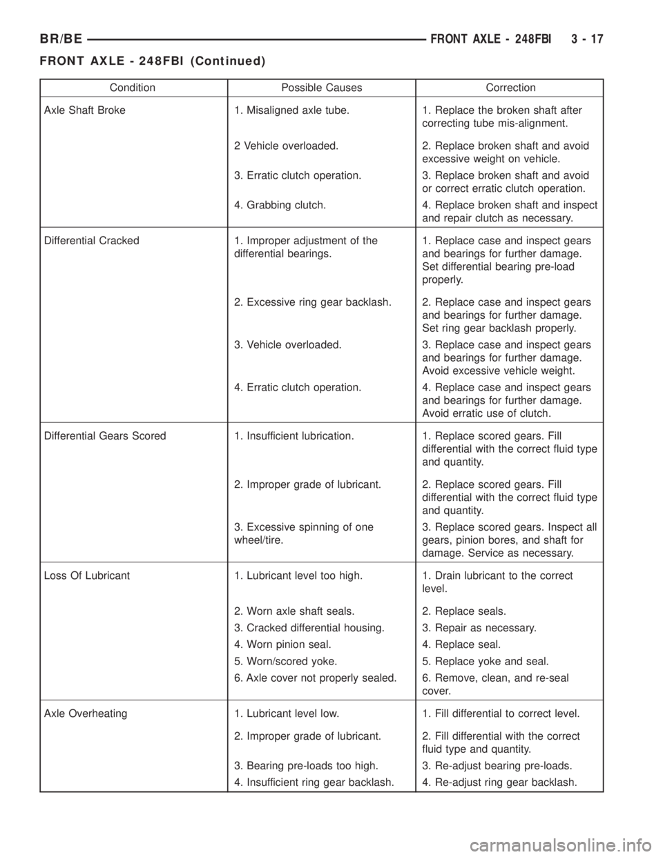
Condition Possible Causes Correction
Axle Shaft Broke 1. Misaligned axle tube. 1. Replace the broken shaft after
correcting tube mis-alignment.
2 Vehicle overloaded. 2. Replace broken shaft and avoid
excessive weight on vehicle.
3. Erratic clutch operation. 3. Replace broken shaft and avoid
or correct erratic clutch operation.
4. Grabbing clutch. 4. Replace broken shaft and inspect
and repair clutch as necessary.
Differential Cracked 1. Improper adjustment of the
differential bearings.1. Replace case and inspect gears
and bearings for further damage.
Set differential bearing pre-load
properly.
2. Excessive ring gear backlash. 2. Replace case and inspect gears
and bearings for further damage.
Set ring gear backlash properly.
3. Vehicle overloaded. 3. Replace case and inspect gears
and bearings for further damage.
Avoid excessive vehicle weight.
4. Erratic clutch operation. 4. Replace case and inspect gears
and bearings for further damage.
Avoid erratic use of clutch.
Differential Gears Scored 1. Insufficient lubrication. 1. Replace scored gears. Fill
differential with the correct fluid type
and quantity.
2. Improper grade of lubricant. 2. Replace scored gears. Fill
differential with the correct fluid type
and quantity.
3. Excessive spinning of one
wheel/tire.3. Replace scored gears. Inspect all
gears, pinion bores, and shaft for
damage. Service as necessary.
Loss Of Lubricant 1. Lubricant level too high. 1. Drain lubricant to the correct
level.
2. Worn axle shaft seals. 2. Replace seals.
3. Cracked differential housing. 3. Repair as necessary.
4. Worn pinion seal. 4. Replace seal.
5. Worn/scored yoke. 5. Replace yoke and seal.
6. Axle cover not properly sealed. 6. Remove, clean, and re-seal
cover.
Axle Overheating 1. Lubricant level low. 1. Fill differential to correct level.
2. Improper grade of lubricant. 2. Fill differential with the correct
fluid type and quantity.
3. Bearing pre-loads too high. 3. Re-adjust bearing pre-loads.
4. Insufficient ring gear backlash. 4. Re-adjust ring gear backlash.
BR/BEFRONT AXLE - 248FBI 3 - 17
FRONT AXLE - 248FBI (Continued)
Page 105 of 2255
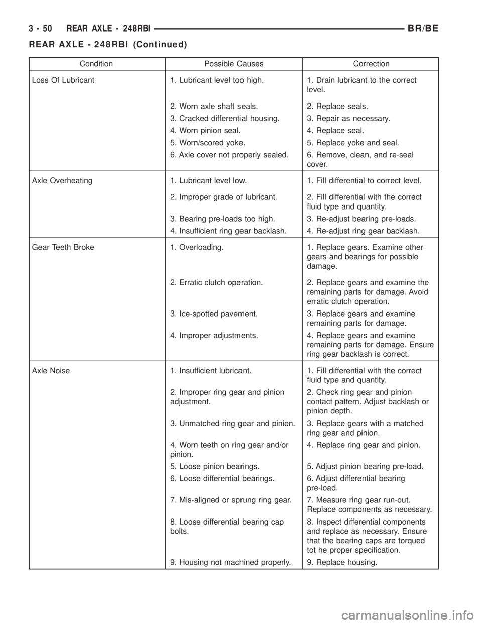
Condition Possible Causes Correction
Loss Of Lubricant 1. Lubricant level too high. 1. Drain lubricant to the correct
level.
2. Worn axle shaft seals. 2. Replace seals.
3. Cracked differential housing. 3. Repair as necessary.
4. Worn pinion seal. 4. Replace seal.
5. Worn/scored yoke. 5. Replace yoke and seal.
6. Axle cover not properly sealed. 6. Remove, clean, and re-seal
cover.
Axle Overheating 1. Lubricant level low. 1. Fill differential to correct level.
2. Improper grade of lubricant. 2. Fill differential with the correct
fluid type and quantity.
3. Bearing pre-loads too high. 3. Re-adjust bearing pre-loads.
4. Insufficient ring gear backlash. 4. Re-adjust ring gear backlash.
Gear Teeth Broke 1. Overloading. 1. Replace gears. Examine other
gears and bearings for possible
damage.
2. Erratic clutch operation. 2. Replace gears and examine the
remaining parts for damage. Avoid
erratic clutch operation.
3. Ice-spotted pavement. 3. Replace gears and examine
remaining parts for damage.
4. Improper adjustments. 4. Replace gears and examine
remaining parts for damage. Ensure
ring gear backlash is correct.
Axle Noise 1. Insufficient lubricant. 1. Fill differential with the correct
fluid type and quantity.
2. Improper ring gear and pinion
adjustment.2. Check ring gear and pinion
contact pattern. Adjust backlash or
pinion depth.
3. Unmatched ring gear and pinion. 3. Replace gears with a matched
ring gear and pinion.
4. Worn teeth on ring gear and/or
pinion.4. Replace ring gear and pinion.
5. Loose pinion bearings. 5. Adjust pinion bearing pre-load.
6. Loose differential bearings. 6. Adjust differential bearing
pre-load.
7. Mis-aligned or sprung ring gear. 7. Measure ring gear run-out.
Replace components as necessary.
8. Loose differential bearing cap
bolts.8. Inspect differential components
and replace as necessary. Ensure
that the bearing caps are torqued
tot he proper specification.
9. Housing not machined properly. 9. Replace housing.
3 - 50 REAR AXLE - 248RBIBR/BE
REAR AXLE - 248RBI (Continued)
Page 137 of 2255
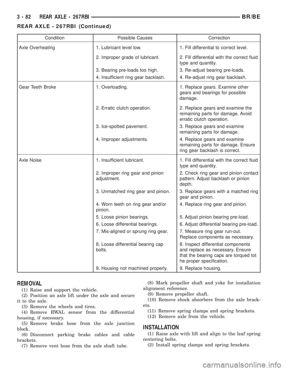
Condition Possible Causes Correction
Axle Overheating 1. Lubricant level low. 1. Fill differential to correct level.
2. Improper grade of lubricant. 2. Fill differential with the correct fluid
type and quantity.
3. Bearing pre-loads too high. 3. Re-adjust bearing pre-loads.
4. Insufficient ring gear backlash. 4. Re-adjust ring gear backlash.
Gear Teeth Broke 1. Overloading. 1. Replace gears. Examine other
gears and bearings for possible
damage.
2. Erratic clutch operation. 2. Replace gears and examine the
remaining parts for damage. Avoid
erratic clutch operation.
3. Ice-spotted pavement. 3. Replace gears and examine
remaining parts for damage.
4. Improper adjustments. 4. Replace gears and examine
remaining parts for damage. Ensure
ring gear backlash is correct.
Axle Noise 1. Insufficient lubricant. 1. Fill differential with the correct fluid
type and quantity.
2. Improper ring gear and pinion
adjustment.2. Check ring gear and pinion contact
pattern. Adjust backlash or pinion
depth.
3. Unmatched ring gear and pinion. 3. Replace gears with a matched ring
gear and pinion.
4. Worn teeth on ring gear and/or
pinion.4. Replace ring gear and pinion.
5. Loose pinion bearings. 5. Adjust pinion bearing pre-load.
6. Loose differential bearings. 6. Adjust differential bearing pre-load.
7. Mis-aligned or sprung ring gear. 7. Measure ring gear run-out.
Replace components as necessary.
8. Loose differential bearing cap
bolts.8. Inspect differential components
and replace as necessary. Ensure
that the bearing caps are torqued tot
he proper specification.
9. Housing not machined properly. 9. Replace housing.
REMOVAL
(1) Raise and support the vehicle.
(2) Position an axle lift under the axle and secure
it to the axle.
(3) Remove the wheels and tires.
(4) Remove RWAL sensor from the differential
housing, if necessary.
(5) Remove brake hose from the axle junction
block.
(6) Disconnect parking brake cables and cable
brackets.
(7) Remove vent hose from the axle shaft tube.(8) Mark propeller shaft and yoke for installation
alignment reference.
(9) Remove propeller shaft.
(10) Remove shock absorbers from the axle brack-
ets.
(11) Remove spring clamps and spring brackets.
(12) Remove axle from the vehicle.
INSTALLATION
(1) Raise axle with lift and align to the leaf spring
centering bolts.
(2) Install spring clamps and spring brackets.
3 - 82 REAR AXLE - 267RBIBR/BE
REAR AXLE - 267RBI (Continued)
Page 166 of 2255
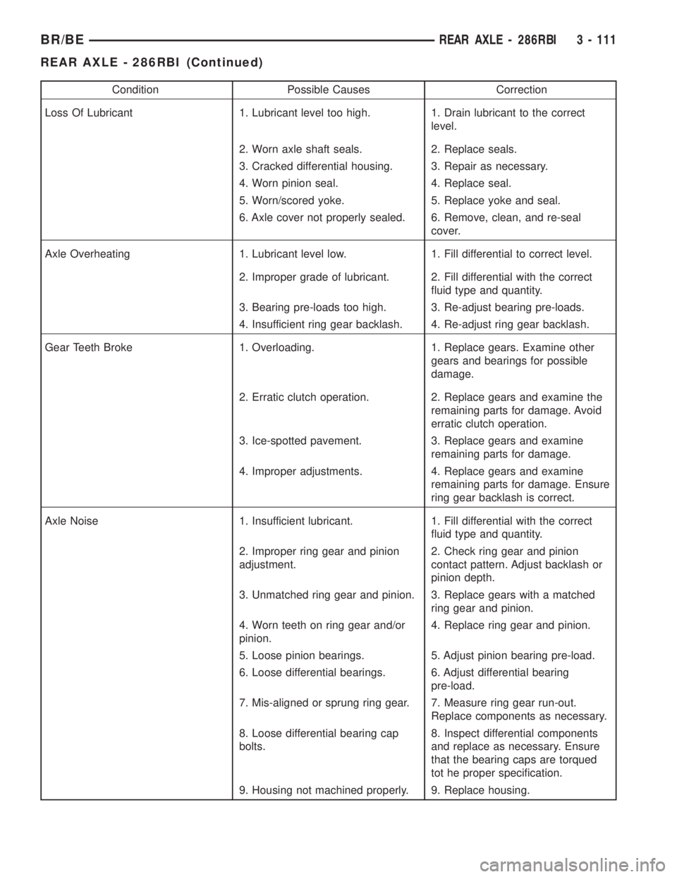
Condition Possible Causes Correction
Loss Of Lubricant 1. Lubricant level too high. 1. Drain lubricant to the correct
level.
2. Worn axle shaft seals. 2. Replace seals.
3. Cracked differential housing. 3. Repair as necessary.
4. Worn pinion seal. 4. Replace seal.
5. Worn/scored yoke. 5. Replace yoke and seal.
6. Axle cover not properly sealed. 6. Remove, clean, and re-seal
cover.
Axle Overheating 1. Lubricant level low. 1. Fill differential to correct level.
2. Improper grade of lubricant. 2. Fill differential with the correct
fluid type and quantity.
3. Bearing pre-loads too high. 3. Re-adjust bearing pre-loads.
4. Insufficient ring gear backlash. 4. Re-adjust ring gear backlash.
Gear Teeth Broke 1. Overloading. 1. Replace gears. Examine other
gears and bearings for possible
damage.
2. Erratic clutch operation. 2. Replace gears and examine the
remaining parts for damage. Avoid
erratic clutch operation.
3. Ice-spotted pavement. 3. Replace gears and examine
remaining parts for damage.
4. Improper adjustments. 4. Replace gears and examine
remaining parts for damage. Ensure
ring gear backlash is correct.
Axle Noise 1. Insufficient lubricant. 1. Fill differential with the correct
fluid type and quantity.
2. Improper ring gear and pinion
adjustment.2. Check ring gear and pinion
contact pattern. Adjust backlash or
pinion depth.
3. Unmatched ring gear and pinion. 3. Replace gears with a matched
ring gear and pinion.
4. Worn teeth on ring gear and/or
pinion.4. Replace ring gear and pinion.
5. Loose pinion bearings. 5. Adjust pinion bearing pre-load.
6. Loose differential bearings. 6. Adjust differential bearing
pre-load.
7. Mis-aligned or sprung ring gear. 7. Measure ring gear run-out.
Replace components as necessary.
8. Loose differential bearing cap
bolts.8. Inspect differential components
and replace as necessary. Ensure
that the bearing caps are torqued
tot he proper specification.
9. Housing not machined properly. 9. Replace housing.
BR/BEREAR AXLE - 286RBI 3 - 111
REAR AXLE - 286RBI (Continued)
Page 195 of 2255
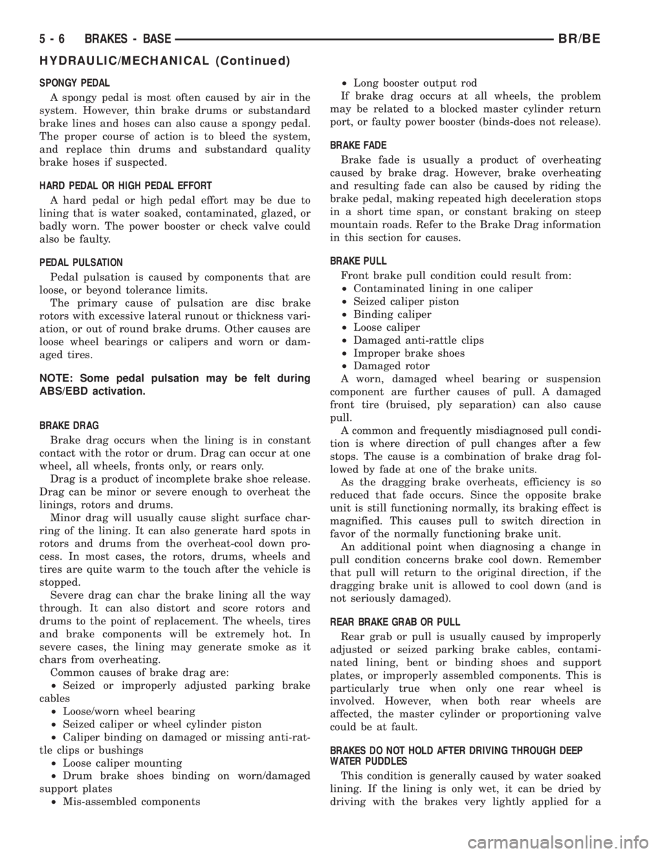
SPONGY PEDAL
A spongy pedal is most often caused by air in the
system. However, thin brake drums or substandard
brake lines and hoses can also cause a spongy pedal.
The proper course of action is to bleed the system,
and replace thin drums and substandard quality
brake hoses if suspected.
HARD PEDAL OR HIGH PEDAL EFFORT
A hard pedal or high pedal effort may be due to
lining that is water soaked, contaminated, glazed, or
badly worn. The power booster or check valve could
also be faulty.
PEDAL PULSATION
Pedal pulsation is caused by components that are
loose, or beyond tolerance limits.
The primary cause of pulsation are disc brake
rotors with excessive lateral runout or thickness vari-
ation, or out of round brake drums. Other causes are
loose wheel bearings or calipers and worn or dam-
aged tires.
NOTE: Some pedal pulsation may be felt during
ABS/EBD activation.
BRAKE DRAG
Brake drag occurs when the lining is in constant
contact with the rotor or drum. Drag can occur at one
wheel, all wheels, fronts only, or rears only.
Drag is a product of incomplete brake shoe release.
Drag can be minor or severe enough to overheat the
linings, rotors and drums.
Minor drag will usually cause slight surface char-
ring of the lining. It can also generate hard spots in
rotors and drums from the overheat-cool down pro-
cess. In most cases, the rotors, drums, wheels and
tires are quite warm to the touch after the vehicle is
stopped.
Severe drag can char the brake lining all the way
through. It can also distort and score rotors and
drums to the point of replacement. The wheels, tires
and brake components will be extremely hot. In
severe cases, the lining may generate smoke as it
chars from overheating.
Common causes of brake drag are:
²Seized or improperly adjusted parking brake
cables
²Loose/worn wheel bearing
²Seized caliper or wheel cylinder piston
²Caliper binding on damaged or missing anti-rat-
tle clips or bushings
²Loose caliper mounting
²Drum brake shoes binding on worn/damaged
support plates
²Mis-assembled components²Long booster output rod
If brake drag occurs at all wheels, the problem
may be related to a blocked master cylinder return
port, or faulty power booster (binds-does not release).
BRAKE FADE
Brake fade is usually a product of overheating
caused by brake drag. However, brake overheating
and resulting fade can also be caused by riding the
brake pedal, making repeated high deceleration stops
in a short time span, or constant braking on steep
mountain roads. Refer to the Brake Drag information
in this section for causes.
BRAKE PULL
Front brake pull condition could result from:
²Contaminated lining in one caliper
²Seized caliper piston
²Binding caliper
²Loose caliper
²Damaged anti-rattle clips
²Improper brake shoes
²Damaged rotor
A worn, damaged wheel bearing or suspension
component are further causes of pull. A damaged
front tire (bruised, ply separation) can also cause
pull.
A common and frequently misdiagnosed pull condi-
tion is where direction of pull changes after a few
stops. The cause is a combination of brake drag fol-
lowed by fade at one of the brake units.
As the dragging brake overheats, efficiency is so
reduced that fade occurs. Since the opposite brake
unit is still functioning normally, its braking effect is
magnified. This causes pull to switch direction in
favor of the normally functioning brake unit.
An additional point when diagnosing a change in
pull condition concerns brake cool down. Remember
that pull will return to the original direction, if the
dragging brake unit is allowed to cool down (and is
not seriously damaged).
REAR BRAKE GRAB OR PULL
Rear grab or pull is usually caused by improperly
adjusted or seized parking brake cables, contami-
nated lining, bent or binding shoes and support
plates, or improperly assembled components. This is
particularly true when only one rear wheel is
involved. However, when both rear wheels are
affected, the master cylinder or proportioning valve
could be at fault.
BRAKES DO NOT HOLD AFTER DRIVING THROUGH DEEP
WATER PUDDLES
This condition is generally caused by water soaked
lining. If the lining is only wet, it can be dried by
driving with the brakes very lightly applied for a
5 - 6 BRAKES - BASEBR/BE
HYDRAULIC/MECHANICAL (Continued)
Page 235 of 2255
IMPROPER RELEASE OR CLUTCH ENGAGEMENT
Clutch release or engagement problems are caused
by wear or damage to one or more clutch compo-
nents. A visual inspection of the release components
will usually reveal the problem part.
Release problems can result in hard shifting and
noise. Items to look for are: leaks at the clutch cylin-
ders and interconnecting line; loose slave cylinder
bolts; worn/loose release fork and pivot stud; dam-
aged release bearing; and a worn clutch disc, or pres-
sure plate.
Normal condensation in vehicles that are stored or
out of service for long periods of time can generate
enough corrosion to make the disc stick to the fly-
wheel, or pressure plate. If this condition is experi-
enced, correction only requires that the disc be
loosened manually through the inspection plate open-
ing.
Engagement problems usually result in slip, chat-
ter/shudder, and noisy operation. The primary causes
are clutch disc contamination; clutch disc wear; mis-
alignment, or distortion; flywheel damage; or a com-
bination of the foregoing. A visual inspection is
required to determine the part actually causing the
problem.
CLUTCH MISALIGNMENT
Clutch components must be in proper alignment
with the crankshaft and transmission input shaft.
Misalignment caused by excessive runout or warpage
of any clutch component will cause grab, chatter and
improper clutch release.
CLUTCH COVER AND DISC RUNOUT
Check the clutch disc before installation. Axial
(face) runout of anewdisc should not exceed 0.50
mm (0.020 in.). Measure runout about 6 mm (1/4 in.)
from the outer edge of the disc facing. Obtain
another disc if runout is excessive.
Check condition of the clutch before installation. A
warped cover or diaphragm spring will cause grab
and incomplete release or engagement. Be careful
when handling the cover and disc. Impact can distort
the cover, diaphragm spring, release fingers and the
hub of the clutch disc.
Use an alignment tool when positioning the disc on
the flywheel. The tool prevents accidental misalign-
ment which could result in cover distortion and disc
damage.
A frequent cause of clutch cover distortion (and
consequent misalignment) is improper bolt tighten-
ing.
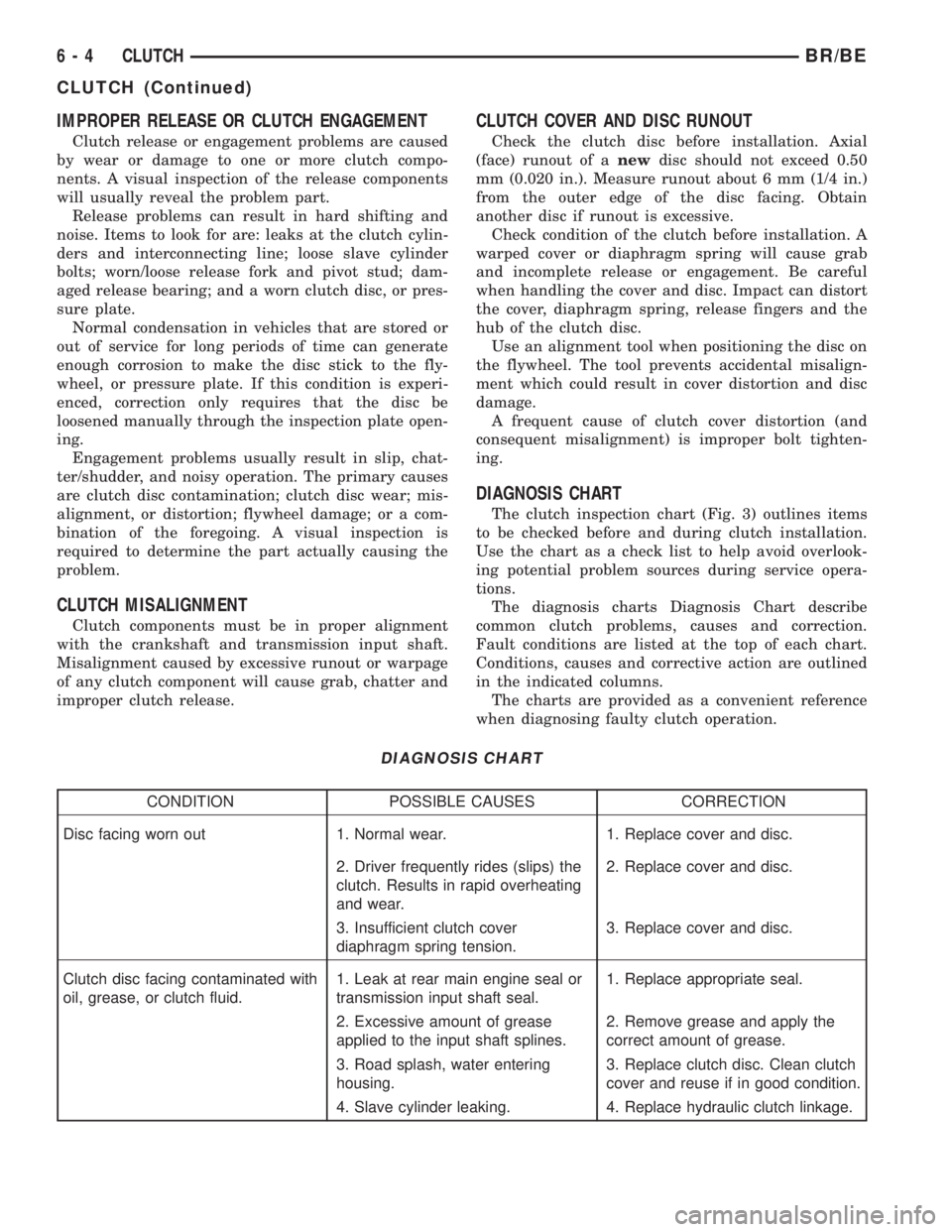
DIAGNOSIS CHART
The clutch inspection chart (Fig. 3) outlines items
to be checked before and during clutch installation.
Use the chart as a check list to help avoid overlook-
ing potential problem sources during service opera-
tions.
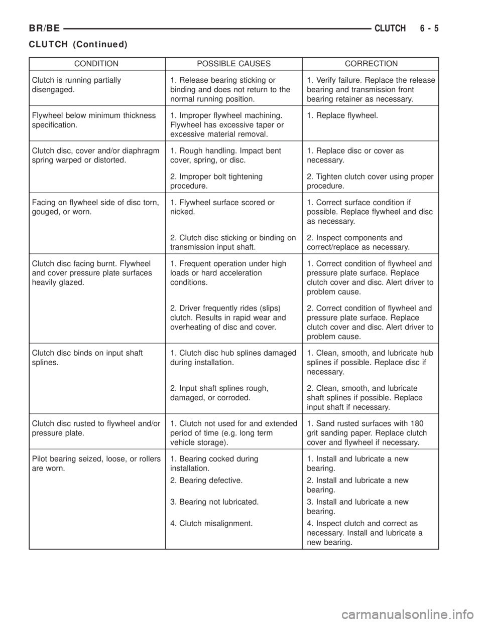
The diagnosis charts Diagnosis Chart describe
common clutch problems, causes and correction.
Fault conditions are listed at the top of each chart.
Conditions, causes and corrective action are outlined
in the indicated columns.
The charts are provided as a convenient reference
when diagnosing faulty clutch operation.
DIAGNOSIS CHART
CONDITION POSSIBLE CAUSES CORRECTION
Disc facing worn out 1. Normal wear. 1. Replace cover and disc.
2. Driver frequently rides (slips) the
clutch. Results in rapid overheating
and wear.2. Replace cover and disc.
3. Insufficient clutch cover
diaphragm spring tension.3. Replace cover and disc.
Clutch disc facing contaminated with
oil, grease, or clutch fluid.1. Leak at rear main engine seal or
transmission input shaft seal.1. Replace appropriate seal.
2. Excessive amount of grease
applied to the input shaft splines.2. Remove grease and apply the
correct amount of grease.
3. Road splash, water entering
housing.3. Replace clutch disc. Clean clutch
cover and reuse if in good condition.
4. Slave cylinder leaking. 4. Replace hydraulic clutch linkage.
6 - 4 CLUTCHBR/BE
CLUTCH (Continued)
Page 236 of 2255
CONDITION POSSIBLE CAUSES CORRECTION
Clutch is running partially
disengaged.1. Release bearing sticking or
binding and does not return to the
normal running position.1. Verify failure. Replace the release
bearing and transmission front
bearing retainer as necessary.
Flywheel below minimum thickness
specification.1. Improper flywheel machining.
Flywheel has excessive taper or
excessive material removal.1. Replace flywheel.
Clutch disc, cover and/or diaphragm
spring warped or distorted.1. Rough handling. Impact bent
cover, spring, or disc.1. Replace disc or cover as
necessary.
2. Improper bolt tightening
procedure.2. Tighten clutch cover using proper
procedure.
Facing on flywheel side of disc torn,
gouged, or worn.1. Flywheel surface scored or
nicked.1. Correct surface condition if
possible. Replace flywheel and disc
as necessary.
2. Clutch disc sticking or binding on
transmission input shaft.2. Inspect components and
correct/replace as necessary.
Clutch disc facing burnt. Flywheel
and cover pressure plate surfaces
heavily glazed.1. Frequent operation under high
loads or hard acceleration
conditions.1. Correct condition of flywheel and
pressure plate surface. Replace
clutch cover and disc. Alert driver to
problem cause.
2. Driver frequently rides (slips)
clutch. Results in rapid wear and
overheating of disc and cover.2. Correct condition of flywheel and
pressure plate surface. Replace
clutch cover and disc. Alert driver to
problem cause.
Clutch disc binds on input shaft
splines.1. Clutch disc hub splines damaged
during installation.1. Clean, smooth, and lubricate hub
splines if possible. Replace disc if
necessary.
2. Input shaft splines rough,
damaged, or corroded.2. Clean, smooth, and lubricate
shaft splines if possible. Replace
input shaft if necessary.
Clutch disc rusted to flywheel and/or
pressure plate.1. Clutch not used for and extended
period of time (e.g. long term
vehicle storage).1. Sand rusted surfaces with 180
grit sanding paper. Replace clutch
cover and flywheel if necessary.
Pilot bearing seized, loose, or rollers
are worn.1. Bearing cocked during
installation.1. Install and lubricate a new
bearing.
2. Bearing defective. 2. Install and lubricate a new
bearing.
3. Bearing not lubricated. 3. Install and lubricate a new
bearing.
4. Clutch misalignment. 4. Inspect clutch and correct as
necessary. Install and lubricate a
new bearing.
BR/BECLUTCH 6 - 5
CLUTCH (Continued)