recommended oil DODGE RAM 2002 Service Owner's Manual
[x] Cancel search | Manufacturer: DODGE, Model Year: 2002, Model line: RAM, Model: DODGE RAM 2002Pages: 2255, PDF Size: 62.07 MB
Page 1174 of 2255
holes and the oil drain-back passages in the cylinder
head, past the valve tappet area, and then returns to
the oil pan (Fig. 52).
DIAGNOSIS AND TESTING
DIAGNOSIS AND TESTINGÐENGINE OIL
LEAKS
Begin with a through visual inspection of the
engine, particularly at the area of the suspected leak.
If an oil leak source is not readily identifiable, the
following steps should be followed:
(1) Do not clean or degrease the engine at this
time because some solvents may cause rubber to
swell, temporarily stopping the leak.
(2) Add an oil-soluble dye (use as recommended by
manufacturer). Start the engine and let idle for
approximately 15 minutes. Check the oil dipstick to
be sure the dye is thoroughly mixed as indicated
with a bright yellow color under a black light source.
(3) Using a black light, inspect the entire engine
for fluorescent dye, particularly at the suspected area
of oil leak. If the oil leak is found and identified,
repair per service manual instructions.
(4) If dye is not observed, drive the vehicle at var-
ious speeds for approximately 24km (15 miles), and
repeat previous step.
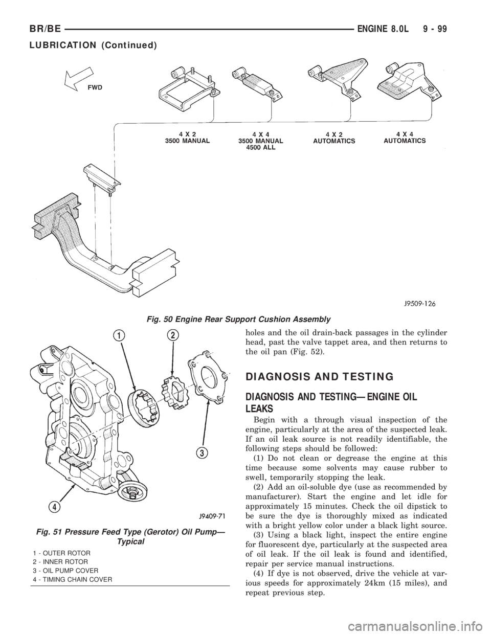
Fig. 50 Engine Rear Support Cushion Assembly
Fig. 51 Pressure Feed Type (Gerotor) Oil PumpÐ
Typical
1 - OUTER ROTOR
2 - INNER ROTOR
3 - OIL PUMP COVER
4 - TIMING CHAIN COVER
BR/BEENGINE 8.0L 9 - 99
LUBRICATION (Continued)
Page 1197 of 2255
STANDARD PROCEDURE
STANDARD PROCEDURE - FORM-IN-PLACE
GASKETS AND SEALERS
There are numerous places where form-in-place
gaskets are used on the engine. Care must be taken
when applying form-in-place gaskets to assure
obtaining the desired results.Do not use form-in-
place gasket material unless specified.Bead size,
continuity, and location are of great importance. Too
thin a bead can result in leakage while too much can
result in spill-over which can break off and obstruct
fluid feed lines. A continuous bead of the proper
width is essential to obtain a leak-free gasket.
There are numerous types of form-in-place gasket
materials that are used in the engine area. Mopart
Engine RTV GEN II, MopartATF-RTV, and Mopart
Gasket Maker gasket materials, each have different
properties and can not be used in place of the other.
MOPARtENGINE RTV GEN II
MopartEngine RTV GEN II is used to seal com-
ponents exposed to engine oil. This material is a spe-
cially designed black silicone rubber RTV that
retains adhesion and sealing properties when
exposed to engine oil. Moisture in the air causes the
material to cure. This material is available in three
ounce tubes and has a shelf life of one year. After one
year this material will not properly cure. Always
inspect the package for the expiration date before
use.
MOPARtATF RTV
MopartATF RTV is a specifically designed black
silicone rubber RTV that retains adhesion and seal-
ing properties to seal components exposed to auto-
matic transmission fluid, engine coolants, and
moisture. This material is available in three ounce
tubes and has a shelf life of one year. After one year
this material will not properly cure. Always inspect
the package for the expiration date before use.
MOPARtGASKET MAKER
MopartGasket Maker is an anaerobic type gasket
material. The material cures in the absence of air
when squeezed between two metallic surfaces. It will
not cure if left in the uncovered tube. The anaerobic
material is for use between two machined surfaces.
Do not use on flexible metal flanges.
MOPARtGASKET SEALANT
MopartGasket Sealant is a slow drying, perma-
nently soft sealer. This material is recommended for
sealing threaded fittings and gaskets against leakage
of oil and coolant. Can be used on threaded and
machined parts under all temperatures. This mate-
rial is used on engines with multi-layer steel (MLS)
cylinder head gaskets. This material also will pre-
vent corrosion. MopartGasket Sealant is available in
a 13 oz. aerosol can or 4oz./16 oz. can w/applicator.
FORM-IN-PLACE GASKET AND SEALER
APPLICATION
Assembling parts using a form-in-place gasket
requires care but it's easier then using precut gas-
kets.
MopartGasket Maker material should be applied
sparingly 1 mm (0.040 in.) diameter or less of sealant
to one gasket surface. Be certain the material sur-
rounds each mounting hole. Excess material can eas-
ily be wiped off. Components should be torqued in
place within 15 minutes. The use of a locating dowel
is recommended during assembly to prevent smear-
ing material off the location.
MopartEngine RTV GEN II or ATF RTV gasket
material should be applied in a continuous bead
approximately 3 mm (0.120 in.) in diameter. All
mounting holes must be circled. For corner sealing, a
3.17 or 6.35 mm (1/8 or 1/4 in.) drop is placed in the
center of the gasket contact area. Uncured sealant
may be removed with a shop towel. Components
should be torqued in place while the sealant is still
wet to the touch (within 10 minutes). The usage of a
locating dowel is recommended during assembly to
prevent smearing material off the location.
MopartGasket Sealant in an aerosol can should be
applied using a thin, even coat sprayed completely
over both surfaces to be joined, and both sides of a
gasket. Then proceed with assembly. Material in a
can w/applicator can be brushed on evenly over the
sealing surfaces. Material in an aerosol can should be
used on engines with multi-layer steel gaskets.
STANDARD PROCEDURE - REPAIR DAMAGED
OR WORN THREADS
CAUTION: Be sure that the tapped holes maintain
the original center line.
Damaged or worn threads can be repaired. Essen-
tially, this repair consists of:
²Drilling out worn or damaged threads.
²Tapping the hole with a special Heli-Coil Tap, or
equivalent.
²Installing an insert into the tapped hole to bring
the hole back to its original thread size.
STANDARD PROCEDUREÐHYDROSTATIC
LOCK
CAUTION: DO NOT use the starter motor to rotate
the crankshaft. Severe damage could occur.
When an engine is suspected of hydrostatic lock
(regardless of what caused the problem), follow the
steps below.
9 - 122 ENGINE 5.9L DIESELBR/BE
Page 1200 of 2255
REMOVALÐCRANKCASE BREATHER VAPOR
CANISTER
NOTE: It is recommended to empty the contents of
the vapor canister at each oil and filter service
interval.
(1) Loosen cap from top of vapor canister.
(2) Remove nut retaining canister to engine front
cover.
(3) Slide clamp upwards on hose, then remove
hose from crankcase breather.
INSTALLATION
INSTALLATIONÐENGINE
(1) Install the engine with the cylinder head cover
and the #5 and 6 rocker arm assemblies removed.
(2) Lower the engine into the compartment and
install the engine mount through bolts and nuts.
(3) Tighten the mount through bolts and nuts to
88 N´m (65 ft. lbs.) torque.
(4) Remove the engine lifting device.
(5) Install the #5 and #6 rocker arms and pedes-
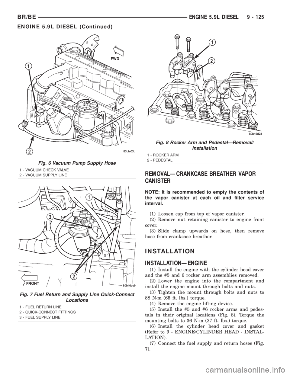
tals in their original locations (Fig. 8). Torque the
mounting bolts to 36 N´m (27 ft. lbs.) torque.
(6) Install the cylinder head cover and gasket
(Refer to 9 - ENGINE/CYLINDER HEAD - INSTAL-
LATION).
(7) Connect the fuel supply and return hoses (Fig.
7).
Fig. 6 Vacuum Pump Supply Hose
1 - VACUUM CHECK VALVE
2 - VACUUM SUPPLY LINE
Fig. 7 Fuel Return and Supply Line Quick-Connect
Locations
1 - FUEL RETURN LINE
2 - QUICK-CONNECT FITTINGS
3 - FUEL SUPPLY LINE
Fig. 8 Rocker Arm and PedestalÐRemoval/
Installation
1 - ROCKER ARM
2 - PEDESTAL
BR/BEENGINE 5.9L DIESEL 9 - 125
ENGINE 5.9L DIESEL (Continued)
Page 1364 of 2255
(c) Check condition of o-ring.
(d) Inspect the 2 WIF sensor probes. Carefully
clean contaminants from sensor probes with a cloth
if necessary. Replace sensor if probes are covered
with contaminants and will not clean up.
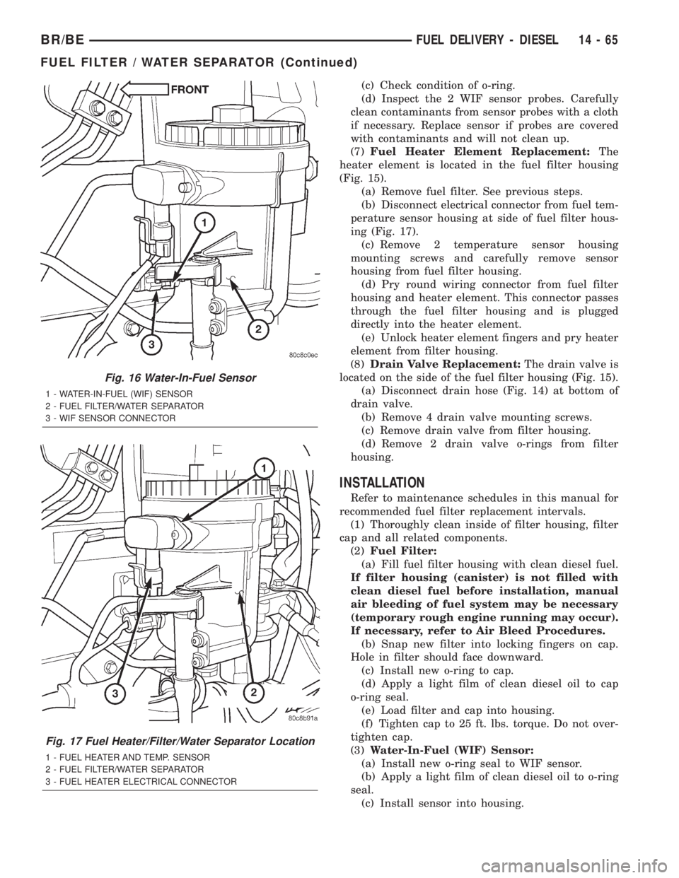
(7)Fuel Heater Element Replacement:The
heater element is located in the fuel filter housing
(Fig. 15).
(a) Remove fuel filter. See previous steps.
(b) Disconnect electrical connector from fuel tem-
perature sensor housing at side of fuel filter hous-
ing (Fig. 17).
(c) Remove 2 temperature sensor housing
mounting screws and carefully remove sensor
housing from fuel filter housing.
(d) Pry round wiring connector from fuel filter
housing and heater element. This connector passes
through the fuel filter housing and is plugged
directly into the heater element.
(e) Unlock heater element fingers and pry heater
element from filter housing.
(8)Drain Valve Replacement:The drain valve is
located on the side of the fuel filter housing (Fig. 15).
(a) Disconnect drain hose (Fig. 14) at bottom of
drain valve.
(b) Remove 4 drain valve mounting screws.
(c) Remove drain valve from filter housing.
(d) Remove 2 drain valve o-rings from filter
housing.
INSTALLATION
Refer to maintenance schedules in this manual for
recommended fuel filter replacement intervals.
(1) Thoroughly clean inside of filter housing, filter
cap and all related components.
(2)Fuel Filter:
(a) Fill fuel filter housing with clean diesel fuel.
If filter housing (canister) is not filled with
clean diesel fuel before installation, manual
air bleeding of fuel system may be necessary
(temporary rough engine running may occur).
If necessary, refer to Air Bleed Procedures.
(b) Snap new filter into locking fingers on cap.
Hole in filter should face downward.
(c) Install new o-ring to cap.
(d) Apply a light film of clean diesel oil to cap
o-ring seal.
(e) Load filter and cap into housing.
(f) Tighten cap to 25 ft. lbs. torque. Do not over-
tighten cap.
(3)Water-In-Fuel (WIF) Sensor:
(a) Install new o-ring seal to WIF sensor.
(b) Apply a light film of clean diesel oil to o-ring
seal.
(c) Install sensor into housing.
Fig. 16 Water-In-Fuel Sensor
1 - WATER-IN-FUEL (WIF) SENSOR
2 - FUEL FILTER/WATER SEPARATOR
3 - WIF SENSOR CONNECTOR
Fig. 17 Fuel Heater/Filter/Water Separator Location
1 - FUEL HEATER AND TEMP. SENSOR
2 - FUEL FILTER/WATER SEPARATOR
3 - FUEL HEATER ELECTRICAL CONNECTOR
BR/BEFUEL DELIVERY - DIESEL 14 - 65
FUEL FILTER / WATER SEPARATOR (Continued)
Page 1456 of 2255
GEAR RATIOS
GEAR RATIO
FIRST 5.61:1
SECOND 3.04:1
THIRD 1.67:1
FOURTH 1.00:1
FIFTH 0.75:1
REVERSE 5.04:1
IDENTIFICATION
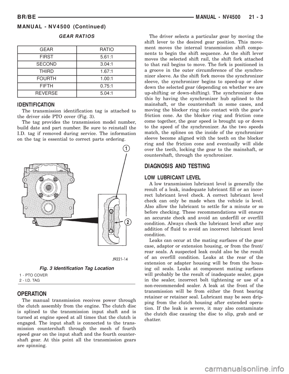
The transmission identification tag is attached to
the driver side PTO cover (Fig. 3).
The tag provides the transmission model number,
build date and part number. Be sure to reinstall the
I.D. tag if removed during service. The information
on the tag is essential to correct parts ordering.
OPERATION
The manual transmission receives power through
the clutch assembly from the engine. The clutch disc
is splined to the transmission input shaft and is
turned at engine speed at all times that the clutch is
engaged. The input shaft is connected to the trans-
mission countershaft through the mesh of fourth
speed gear on the input shaft and the fourth counter-
shaft gear. At this point all the transmission gears
are spinning.The driver selects a particular gear by moving the
shift lever to the desired gear position. This move-
ment moves the internal transmission shift compo-
nents to begin the shift sequence. As the shift lever
moves the selected shift rail, the shift fork attached
to that rail begins to move. The fork is positioned in
a groove in the outer circumference of the synchro-
nizer sleeve. As the shift fork moves the synchronizer
sleeve, the synchronizer begins to speed-up or slow
down the selected gear (depending on whether we are
up-shifting or down-shifting). The synchronizer does
this by having the synchronizer hub splined to the
mainshaft, or the countershaft in some cases, and
moving the blocker ring into contact with the gear's
friction cone. As the blocker ring and friction cone
come together, the gear speed is brought up or down
to the speed of the synchronizer. As the two speeds
match, the splines on the inside of the synchronizer
sleeve become aligned with the teeth on the blocker
ring and the friction cone and eventually will slide
over the teeth, locking the gear to the mainshaft, or
countershaft, through the synchronizer.
DIAGNOSIS AND TESTING
LOW LUBRICANT LEVEL
A low transmission lubricant level is generally the
result of a leak, inadequate lubricant fill or an incor-
rect lubricant level check. A correct lubricant level
check can only be made when the vehicle is level.
Also allow the lubricant to settle for a minute or so
before checking. These recommendations will ensure
an accurate check and avoid an underfill or overfill
condition. Always check the lubricant level after any
addition of fluid to avoid an incorrect lubricant level
condition.
Leaks can occur at the mating surfaces of the gear
case, adaptor or extension housing, or from the front/
rear seals. A suspected leak could also be the result
of an overfill condition. Leaks at the rear of the
extension or adapter housing will be from the hous-
ing oil seals. Leaks at component mating surfaces
will probably be the result of inadequate sealer, gaps
in the sealer, incorrect bolt tightening or use of a
non-recommended sealer. A leak at the front of the
transmission will be from either the front bearing
retainer or retainer seal. Lubricant may be seen drip-
ping from the clutch housing after extended opera-
tion. If the leak is severe, it may also contaminate
the clutch disc causing the disc to slip, grab and or
chatter.
Fig. 3 Identification Tag Location
1 - PTO COVER
2 - I.D. TAG
BR/BEMANUAL - NV4500 21 - 3
MANUAL - NV4500 (Continued)
Page 1501 of 2255
OPERATION
The driver selects a particular gear by moving the
shift lever to the desired gear position. As the shift
lever moves the selected shift rail, the shift fork
attached to that rail begins to move. The fork is posi-
tioned in a groove in the outer circumference of the
synchronizer sleeve. As the shift fork moves the syn-
chronizer sleeve, the synchronizer begins to speed-up
or slow down the selected gear (depending on
whether we are up-shifting or down-shifting). The
synchronizer does this by having the synchronizer
hub splined to the mainshaft or the countershaft in
some cases, and moving the blocker ring into contact
with the gear's friction cone. As the blocker ring and
friction cone come together, the gear speed is brought
up or down to the speed of the synchronizer. As the
two speeds match, the splines on the inside of the
synchronizer sleeve become aligned with the teeth on
the blocker ring and friction cone and eventually willslide over the teeth, locking the gear to the main-
shaft or countershaft through the synchronizer.
DIAGNOSIS AND TESTING
LOW LUBRICANT LEVEL
A low transmission lubricant level is generally the
result of a leak, inadequate lubricant fill or an incor-
rect lubricant level check. A correct lubricant level
check can only be made when the vehicle is level.
Also allow the lubricant to settle for a minute or so
before checking. These recommendations will ensure
an accurate check and avoid an underfill or overfill
condition. Always check the lubricant level after any
addition of fluid to avoid an incorrect lubricant level
condition.
Leaks can occur at the mating surfaces of the gear
case, adaptor or extension housing, or from the front/
rear seals. A suspected leak could also be the result
of an overfill condition. Leaks at the rear of the
extension or adapter housing will be from the hous-
ing oil seals. Leaks at component mating surfaces
will probably be the result of inadequate sealer, gaps
in the sealer, incorrect bolt tightening or use of a
non-recommended sealer. A leak at the front of the
transmission will be from either the front bearing
retainer or retainer seal. Lubricant may be seen drip-
ping from the clutch housing after extended opera-
tion. If the leak is severe, it may also contaminate
the clutch disc causing the disc to slip, grab and or
chatter.
HARD SHIFTING
Hard shifting is usually caused by a low lubricant
level, improper or contaminated lubricants. The con-
sequence of using non-recommended lubricants is
noise, excessive wear, internal bind and hard shift-
ing. Substantial lubricant leaks can result in gear,
shift rail, synchro, and bearing damage. If a leak
goes undetected for an extended period, the first indi-
cations of component damage are usually hard shift-
ing and noise.
Component damage, incorrect clutch adjustment or
damaged clutch pressure plate or disc are additional
probable causes of increased shift effort. Incorrect
adjustment or a worn/damaged pressure plate or disc
can cause incorrect release. If clutch problem is
advanced, gear clash during shifts can result. Worn
or damaged synchro rings can cause gear clash when
shifting into any forward gear. In some new or
rebuilt transmissions, new synchro rings may tend to
stick slightly causing hard or noisy shifts. In most
cases this condition will decline as the rings wear-in.
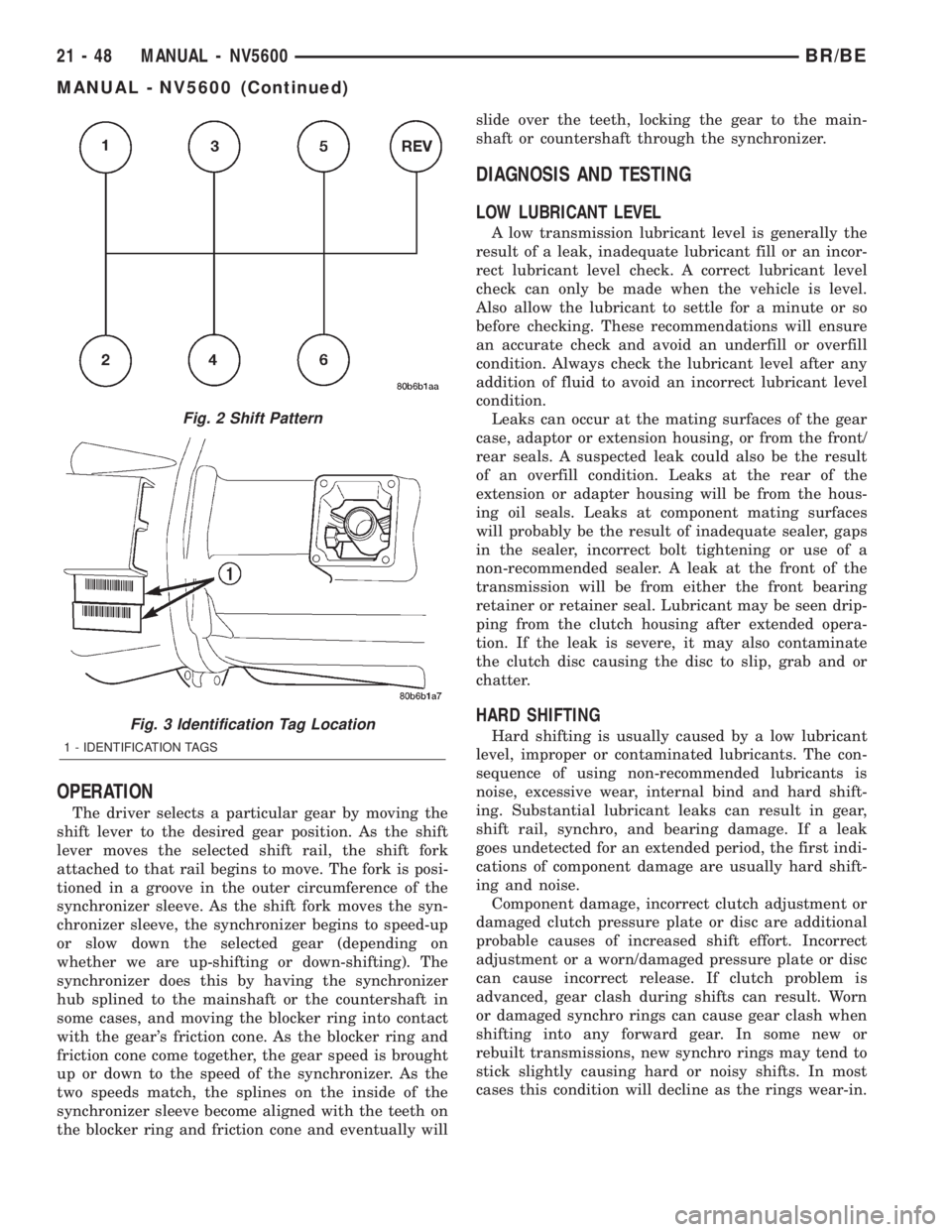
Fig. 2 Shift Pattern
Fig. 3 Identification Tag Location
1 - IDENTIFICATION TAGS
21 - 48 MANUAL - NV5600BR/BE
MANUAL - NV5600 (Continued)
Page 1575 of 2255
CLEANING
Clean the case in a solvent tank. Flush the case
bores and fluid passages thoroughly with solvent.
Dry the case and all fluid passages with compressed
air. Be sure all solvent is removed from the case and
that all fluid passages are clear.
NOTE: Do not use shop towels or rags to dry the
case (or any other transmission component) unless
they are made from lint-free materials. Lint will stick
to case surfaces and transmission components and
circulate throughout the transmission after assem-
bly. A sufficient quantity of lint can block fluid pas-
sages and interfere with valve body operation.
Lubricate transmission parts with MopartATF +4,
type 9602, transmission fluid during overhaul and
assembly. Use petroleum jelly, MopartDoor Ease, or
Ru-GlydeŸ to prelubricate seals, O-rings, and thrust
washers. Petroleum jelly can also be used to hold
parts in place during reassembly.
INSPECTION
Inspect the case for cracks, porous spots, worn
bores, or damaged threads. Damaged threads can be
repaired with Helicoil thread inserts. However, the
case will have to be replaced if it exhibits any type of
damage or wear.
Lubricate the front band adjusting screw threads
with petroleum jelly and thread the screw part-way
into the case. Be sure the screw turns freely.Inspect the transmission bushings during overhaul.
Bushing condition is important as worn, scored bush-
ings contribute to low pressures, clutch slip and
accelerated wear of other components. However, do
not replace bushings as a matter of course. Replace
bushings only when they are actually worn, or
scored.
Use recommended tools to replace bushings. The
tools are sized and designed to remove, install, and
seat bushings correctly. The bushing replacement
tools are included in Bushing Tool Set C-3887-B.
Pre-sized service bushings are available for
replacement purposes. Only the sun gear bushings
are not serviced.
The use of crocus cloth is permissible where neces-
sary, providing it is used carefully. When used on
shafts, or valves, use extreme care to avoid rounding
off sharp edges. Sharp edges are vital as they pre-
vent foreign matter from getting between the valve
and valve bore.
Do not reuse oil seals, gaskets, seal rings, or
O-rings during overhaul. Replace these parts as a
matter of course. Also do not reuse snap rings or
E-clips that are bent or distorted. Replace these parts
as well.
ASSEMBLY
Do not allow dirt, grease, or foreign material to
enter the case or transmission components during
assembly. Keep the transmission case and compo-
nents clean. Also make sure the tools and workbench
area used for reassembly operations are equally
clean.
Shop towels used for wiping off tools and your
hands must be made fromlint freematerials. Lint
will stick to transmission parts and could interfere
with valve operation or even restrict fluid passages.
Lubricate transmission clutch and gear compo-
nents with MopartATF +4, type 9602, during reas-
sembly. Soak clutch discs in transmission fluid before
installation.
Use MopartDoor Ease, or Ru-GlydeŸ on piston
seals and O-rings to ease installation. Petroleum jelly
can also be used to lubricate and hold thrust washers
and plates in position during assembly.
Do not use chassis grease, bearing grease,
white grease, or similar lubricants on any part.
These types of lubricants can eventually block or
restrict fluid passages and valve operation. Use
petroleum jelly only.
Do not force parts into place. The transmission
components and sub-assemblies are easily installed
by hand when properly aligned. If a part seems dif-
ficult to install, it is either misaligned or incorrectly
assembled. Verify that thrust washers, thrust plates
and seal rings are correctly positioned.
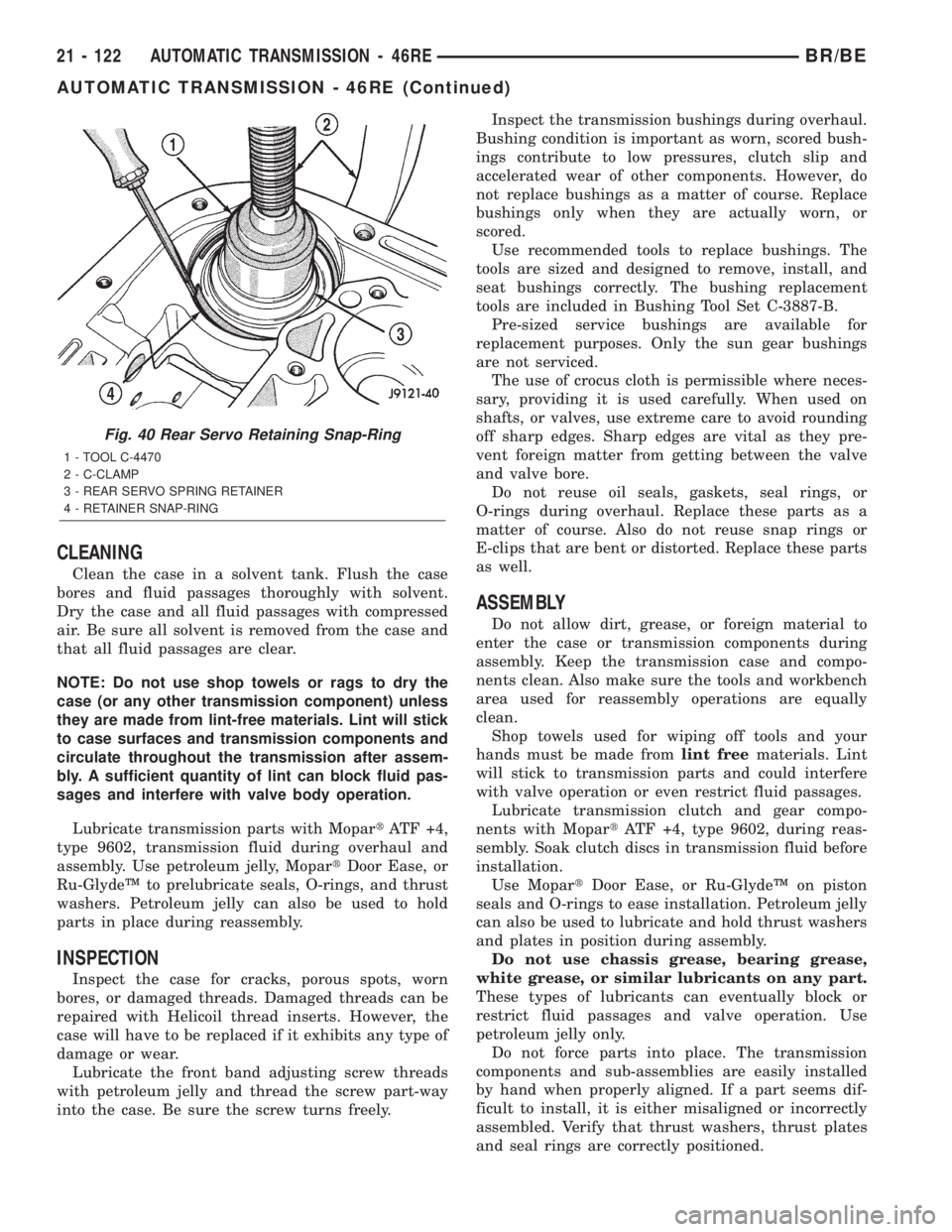
Fig. 40 Rear Servo Retaining Snap-Ring
1 - TOOL C-4470
2 - C-CLAMP
3 - REAR SERVO SPRING RETAINER
4 - RETAINER SNAP-RING
21 - 122 AUTOMATIC TRANSMISSION - 46REBR/BE
AUTOMATIC TRANSMISSION - 46RE (Continued)
Page 1583 of 2255
(a) Loosen locknut on each band adjusting screw
4-5 turns.
(b) Tighten both adjusting screws to 8 N´m (72
in. lbs.).
(c) Back off front band adjusting screw 2-7/8
turns.
(d) Back off rear band adjusting screw 2 turns.
(e) Hold each adjusting screw in position and
tighten locknut to 34 N´m (25 ft. lbs.) torque.
(2) Install magnet in oil pan. Magnet seats on
small protrusion at corner of pan.
(3) Position new oil pan gasket on case and install
oil pan. Tighten pan bolts to 13.6 N´m (125 in. lbs.).
(4) Install throttle valve and shift selector levers
on valve body manual lever shaft.
(5) Apply small quantity of dielectric grease to ter-
minal pins of solenoid case connector and neutral
switch.
(6) Fill transmission with recommended fluid.
Refer to Service Procedures section of this group.
INSTALLATION
(1) Check torque converter hub and hub drive
notches for sharp edges burrs, scratches, or nicks.
Polish the hub and notches with 320/400 grit paper
and crocus cloth if necessary. The hub must be
smooth to avoid damaging pump seal at installation.
(2) Lubricate pocket in the rear oil pump seal lip
with transmission fluid.(3) Lubricate converter pilot hub of the crankshaft
with a light coating of MopartHigh Temp Grease.
(4) Align and install converter in oil pump.
(5) Carefully insert converter in oil pump. Then
rotate converter back and forth until fully seated in
pump gears.
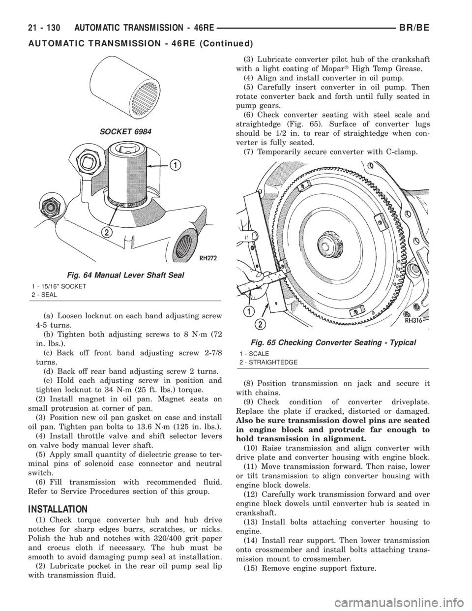
(6) Check converter seating with steel scale and
straightedge (Fig. 65). Surface of converter lugs
should be 1/2 in. to rear of straightedge when con-
verter is fully seated.
(7) Temporarily secure converter with C-clamp.
(8) Position transmission on jack and secure it
with chains.
(9) Check condition of converter driveplate.
Replace the plate if cracked, distorted or damaged.
Also be sure transmission dowel pins are seated
in engine block and protrude far enough to
hold transmission in alignment.
(10) Raise transmission and align converter with
drive plate and converter housing with engine block.
(11) Move transmission forward. Then raise, lower
or tilt transmission to align converter housing with
engine block dowels.
(12) Carefully work transmission forward and over
engine block dowels until converter hub is seated in
crankshaft.
(13) Install bolts attaching converter housing to
engine.
(14) Install rear support. Then lower transmission
onto crossmember and install bolts attaching trans-
mission mount to crossmember.
(15) Remove engine support fixture.
SOCKET 6984
Fig. 64 Manual Lever Shaft Seal
1 - 15/16©© SOCKET
2 - SEAL
Fig. 65 Checking Converter Seating - Typical
1 - SCALE
2 - STRAIGHTEDGE
21 - 130 AUTOMATIC TRANSMISSION - 46REBR/BE
AUTOMATIC TRANSMISSION - 46RE (Continued)
Page 1652 of 2255

INSPECTION
Inspect the planetary gear sets and annulus gears.
The planetary pinions, shafts, washers, and retaining
pins are serviceable. However, if a pinion carrier is
damaged, the entire planetary gear set must be
replaced as an assembly.
Replace the annulus gears if the teeth are chipped,
broken, or worn, or the gear is cracked. Replace the
planetary thrust plates and the tabbed thrust wash-
ers if cracked, scored or worn.
Inspect the machined surfaces of the intermediate
shaft. Be sure the oil passages are open and clear.
Replace the shaft if scored, pitted, or damaged.
Inspect the sun gear and driving shell. If either
component is worn or damaged, remove the sun gear
rear retaining ring and separate the sun gear andthrust plate from the driving shell. Then replace the
necessary component.
Replace the sun gear as an assembly if the gear
teeth are chipped or worn. Also replace the gear as
an assembly if the bushings are scored or worn. The
sun gear bushings are not serviceable. Replace the
thrust plate if worn, or severely scored. Replace the
driving shell if distorted, cracked, or damaged in any
way.
Replace all snap-rings during geartrain assembly.
Reusing snap-rings is not recommended.
ASSEMBLY
(1) Lubricate sun gear and planetary gears with
transmission fluid during assembly. Use petroleum
jelly to lubricate intermediate shaft bushing surfaces,
thrust washers and thrust plates and to hold these
parts in place during assembly.
Fig. 206 Sun Gear And Driving Shell Removal
1 - INTERMEDIATE SHAFT
2 - DRIVING SHELL
3 - SUN GEAR
Fig. 207 Rear Planetary Thrust Washer Removal
1 - SUN GEAR
2 - REAR PLANETARY THRUST WASHER
3 - DRIVING SHELL
Fig. 208 Rear Planetary And Annulus Gear Removal
1 - INTERMEDIATE SHAFT
2 - REAR ANNULUS GEAR
3 - REAR PLANETARY GEAR
Fig. 209 Rear Annulus Thrust Plate Removal
1 - REAR ANNULUS GEAR
2 - THRUST PLATE
BR/BEAUTOMATIC TRANSMISSION - 46RE 21 - 199
PLANETARY GEARTRAIN/OUTPUT SHAFT (Continued)
Page 1670 of 2255
CAUTION: Verify that transmission is secure on the
lifting device or work surface, the center of gravity
of the transmission will shift when the torque con-
verter is removed creating an unstable condition.
The torque converter is a heavy unit. Use caution
when separating the torque converter from the
transmission.
(3) Pull the torque converter forward until the cen-
ter hub clears the oil pump seal.
(4) Separate the torque converter from the trans-
mission.
INSTALLATION
Check converter hub and drive notches for sharp
edges, burrs, scratches, or nicks. Polish the hub and
notches with 320/400 grit paper or crocus cloth if nec-
essary. The hub must be smooth to avoid damaging
the pump seal at installation.
(1) Lubricate oil pump seal lip with transmission
fluid.
(2) Place torque converter in position on transmis-
sion.
CAUTION: Do not damage oil pump seal or bushing
while inserting torque converter into the front of the
transmission.
(3) Align torque converter to oil pump seal open-
ing.
(4) Insert torque converter hub into oil pump.
(5) While pushing torque converter inward, rotate
converter until converter is fully seated in the oil
pump gears.
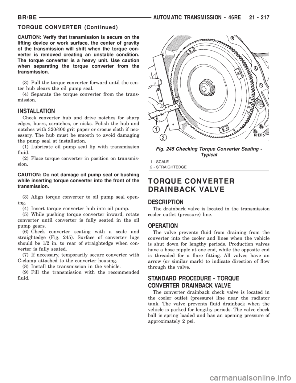
(6) Check converter seating with a scale and
straightedge (Fig. 245). Surface of converter lugs
should be 1/2 in. to rear of straightedge when con-
verter is fully seated.
(7) If necessary, temporarily secure converter with
C-clamp attached to the converter housing.
(8) Install the transmission in the vehicle.
(9) Fill the transmission with the recommended
fluid.
TORQUE CONVERTER
DRAINBACK VALVE
DESCRIPTION
The drainback valve is located in the transmission
cooler outlet (pressure) line.
OPERATION
The valve prevents fluid from draining from the
converter into the cooler and lines when the vehicle
is shut down for lengthy periods. Production valves
have a hose nipple at one end, while the opposite end
is threaded for a flare fitting. All valves have an
arrow (or similar mark) to indicate direction of flow
through the valve.
STANDARD PROCEDURE - TORQUE
CONVERTER DRAINBACK VALVE
The converter drainback check valve is located in
the cooler outlet (pressure) line near the radiator
tank. The valve prevents fluid drainback when the
vehicle is parked for lengthy periods. The valve check
ball is spring loaded and has an opening pressure of
approximately 2 psi.
Fig. 245 Checking Torque Converter Seating -
Typical
1 - SCALE
2 - STRAIGHTEDGE
BR/BEAUTOMATIC TRANSMISSION - 46RE 21 - 217
TORQUE CONVERTER (Continued)