engine DODGE RAM 2002 Service Repair Manual
[x] Cancel search | Manufacturer: DODGE, Model Year: 2002, Model line: RAM, Model: DODGE RAM 2002Pages: 2255, PDF Size: 62.07 MB
Page 1839 of 2255
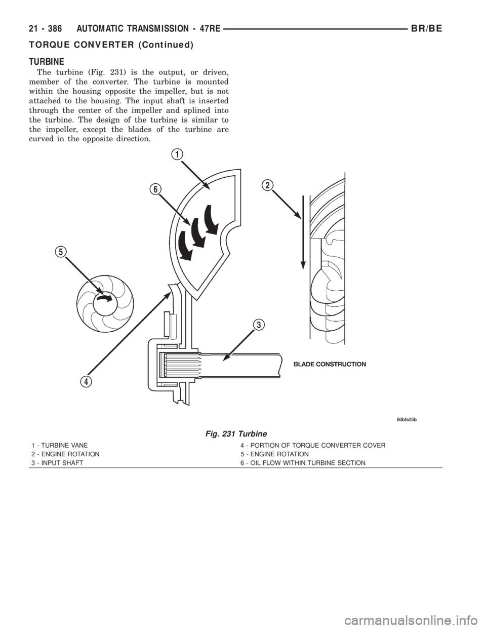
TURBINE
The turbine (Fig. 231) is the output, or driven,
member of the converter. The turbine is mounted
within the housing opposite the impeller, but is not
attached to the housing. The input shaft is inserted
through the center of the impeller and splined into
the turbine. The design of the turbine is similar to
the impeller, except the blades of the turbine are
curved in the opposite direction.
Fig. 231 Turbine
1 - TURBINE VANE 4 - PORTION OF TORQUE CONVERTER COVER
2 - ENGINE ROTATION 5 - ENGINE ROTATION
3 - INPUT SHAFT 6 - OIL FLOW WITHIN TURBINE SECTION
21 - 386 AUTOMATIC TRANSMISSION - 47REBR/BE
TORQUE CONVERTER (Continued)
Page 1841 of 2255
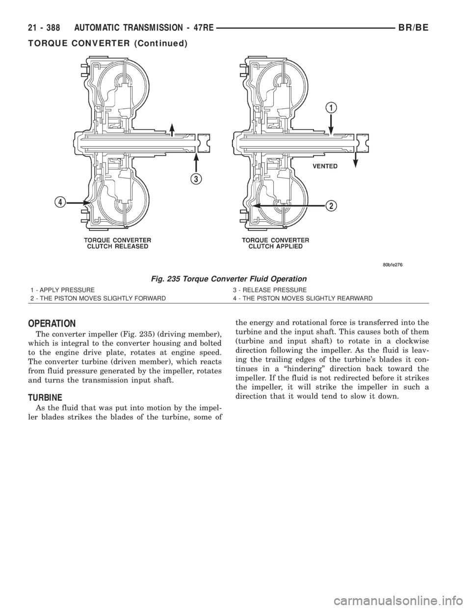
OPERATION
The converter impeller (Fig. 235) (driving member),
which is integral to the converter housing and bolted
to the engine drive plate, rotates at engine speed.
The converter turbine (driven member), which reacts
from fluid pressure generated by the impeller, rotates
and turns the transmission input shaft.
TURBINE
As the fluid that was put into motion by the impel-
ler blades strikes the blades of the turbine, some ofthe energy and rotational force is transferred into the
turbine and the input shaft. This causes both of them
(turbine and input shaft) to rotate in a clockwise
direction following the impeller. As the fluid is leav-
ing the trailing edges of the turbine's blades it con-
tinues in a ªhinderingº direction back toward the
impeller. If the fluid is not redirected before it strikes
the impeller, it will strike the impeller in such a
direction that it would tend to slow it down.
Fig. 235 Torque Converter Fluid Operation
1 - APPLY PRESSURE 3 - RELEASE PRESSURE
2 - THE PISTON MOVES SLIGHTLY FORWARD 4 - THE PISTON MOVES SLIGHTLY REARWARD
21 - 388 AUTOMATIC TRANSMISSION - 47REBR/BE
TORQUE CONVERTER (Continued)
Page 1842 of 2255
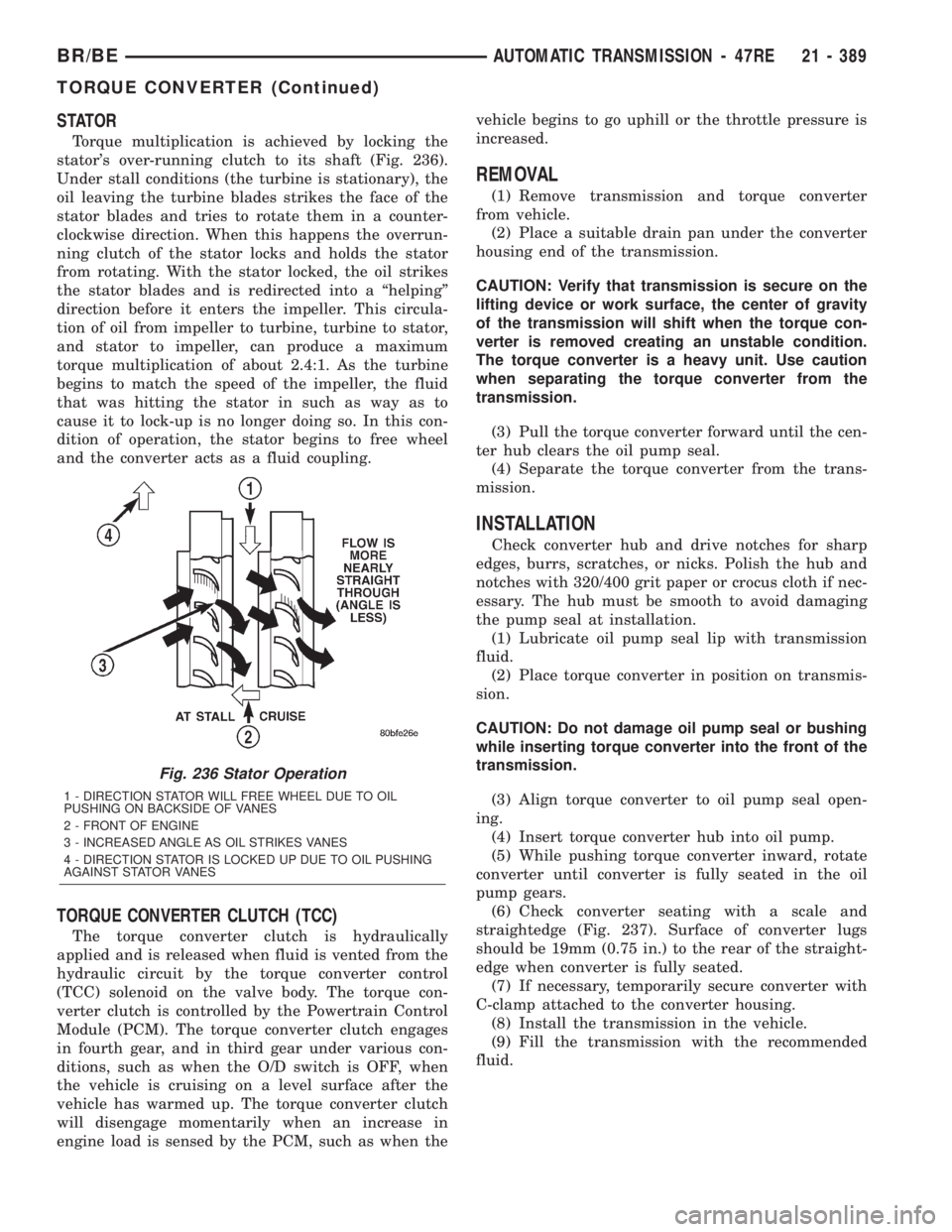
STATOR
Torque multiplication is achieved by locking the
stator's over-running clutch to its shaft (Fig. 236).
Under stall conditions (the turbine is stationary), the
oil leaving the turbine blades strikes the face of the
stator blades and tries to rotate them in a counter-
clockwise direction. When this happens the overrun-
ning clutch of the stator locks and holds the stator
from rotating. With the stator locked, the oil strikes
the stator blades and is redirected into a ªhelpingº
direction before it enters the impeller. This circula-
tion of oil from impeller to turbine, turbine to stator,
and stator to impeller, can produce a maximum
torque multiplication of about 2.4:1. As the turbine
begins to match the speed of the impeller, the fluid
that was hitting the stator in such as way as to
cause it to lock-up is no longer doing so. In this con-
dition of operation, the stator begins to free wheel
and the converter acts as a fluid coupling.
TORQUE CONVERTER CLUTCH (TCC)
The torque converter clutch is hydraulically
applied and is released when fluid is vented from the
hydraulic circuit by the torque converter control
(TCC) solenoid on the valve body. The torque con-
verter clutch is controlled by the Powertrain Control
Module (PCM). The torque converter clutch engages
in fourth gear, and in third gear under various con-
ditions, such as when the O/D switch is OFF, when
the vehicle is cruising on a level surface after the
vehicle has warmed up. The torque converter clutch
will disengage momentarily when an increase in
engine load is sensed by the PCM, such as when thevehicle begins to go uphill or the throttle pressure is
increased.
REMOVAL
(1) Remove transmission and torque converter
from vehicle.
(2) Place a suitable drain pan under the converter
housing end of the transmission.
CAUTION: Verify that transmission is secure on the
lifting device or work surface, the center of gravity
of the transmission will shift when the torque con-
verter is removed creating an unstable condition.
The torque converter is a heavy unit. Use caution
when separating the torque converter from the
transmission.
(3) Pull the torque converter forward until the cen-
ter hub clears the oil pump seal.
(4) Separate the torque converter from the trans-
mission.
INSTALLATION
Check converter hub and drive notches for sharp
edges, burrs, scratches, or nicks. Polish the hub and
notches with 320/400 grit paper or crocus cloth if nec-
essary. The hub must be smooth to avoid damaging
the pump seal at installation.
(1) Lubricate oil pump seal lip with transmission
fluid.
(2) Place torque converter in position on transmis-
sion.
CAUTION: Do not damage oil pump seal or bushing
while inserting torque converter into the front of the
transmission.
(3) Align torque converter to oil pump seal open-
ing.
(4) Insert torque converter hub into oil pump.
(5) While pushing torque converter inward, rotate
converter until converter is fully seated in the oil
pump gears.
(6) Check converter seating with a scale and
straightedge (Fig. 237). Surface of converter lugs
should be 19mm (0.75 in.) to the rear of the straight-
edge when converter is fully seated.
(7) If necessary, temporarily secure converter with
C-clamp attached to the converter housing.
(8) Install the transmission in the vehicle.
(9) Fill the transmission with the recommended
fluid.
Fig. 236 Stator Operation
1 - DIRECTION STATOR WILL FREE WHEEL DUE TO OIL
PUSHING ON BACKSIDE OF VANES
2 - FRONT OF ENGINE
3 - INCREASED ANGLE AS OIL STRIKES VANES
4 - DIRECTION STATOR IS LOCKED UP DUE TO OIL PUSHING
AGAINST STATOR VANES
BR/BEAUTOMATIC TRANSMISSION - 47RE 21 - 389
TORQUE CONVERTER (Continued)
Page 1849 of 2255
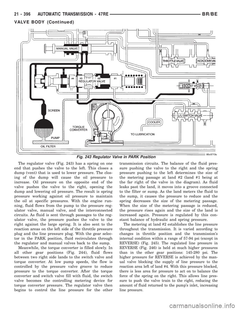
The regulator valve (Fig. 243) has a spring on one
end that pushes the valve to the left. This closes a
dump (vent) that is used to lower pressure. The clos-
ing of the dump will cause the oil pressure to
increase. Oil pressure on the opposite end of the
valve pushes the valve to the right, opening the
dump and lowering oil pressure. The result is spring
pressure working against oil pressure to maintain
the oil at specific pressures. With the engine run-
ning, fluid flows from the pump to the pressure reg-
ulator valve, manual valve, and the interconnected
circuits. As fluid is sent through passages to the reg-
ulator valve, the pressure pushes the valve to the
right against the large spring. It is also sent to the
reaction areas on the left side of the throttle pressure
plug and the line pressure plug. With the gear selec-
tor in the PARK position, fluid recirculates through
the regulator and manual valves back to the sump.
Meanwhile, the torque converter is filled slowly. In
all other gear positions (Fig. 244), fluid flows
between two right side lands to the switch valve and
torque converter. At low pump speeds, the flow is
controlled by the pressure valve groove to reduce
pressure to the torque converter. After the torque
converter and switch valve fill with fluid, the switch
valve becomes the controlling metering device for
torque converter pressure. The regulator valve then
begins to control the line pressure for the othertransmission circuits. The balance of the fluid pres-
sure pushing the valve to the right and the spring
pressure pushing to the left determines the size of
the metering passage at land #2 (land #1 being at
the far right of the valve in the diagram). As fluid
leaks past the land, it moves into a groove connected
to the filter or sump. As the land meters the fluid to
the sump, it causes the pressure to reduce and the
spring decreases the size of the metering passage.
When the size of the metering passage is reduced,
the pressure rises again and the size of the land is
increased again. Pressure is regulated by this con-
stant balance of hydraulic and spring pressure.
The metering at land #2 establishes the line pressure
throughout the transmission. It is varied according to
changes in throttle position and the transmission's
internal condition within a range of 57-94 psi (except in
REVERSE) (Fig. 245). The regulated line pressure in
REVERSE (Fig. 246) is held at much higher pressures
than in the other gear positions: 145-280 psi. The
higher pressure for REVERSE is achieved by the man-
ual valve blocking the supply of line pressure to the
reaction area left of land #4. With this pressure blocked,
there is less area for pressure to act on to balance the
force of the spring on the right. This allows line pres-
sure to push the valve train to the right, reducing the
amount of fluid returned to the pump's inlet, increasing
line pressure.
Fig. 243 Regulator Valve in PARK Position
21 - 396 AUTOMATIC TRANSMISSION - 47REBR/BE
VALVE BODY (Continued)
Page 1857 of 2255
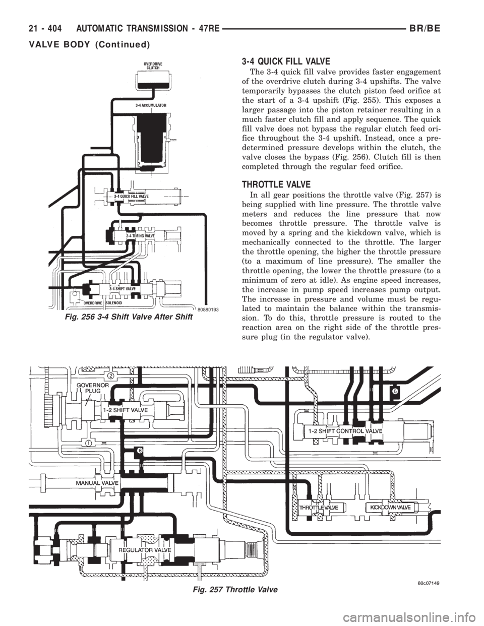
3-4 QUICK FILL VALVE
The 3-4 quick fill valve provides faster engagement
of the overdrive clutch during 3-4 upshifts. The valve
temporarily bypasses the clutch piston feed orifice at
the start of a 3-4 upshift (Fig. 255). This exposes a
larger passage into the piston retainer resulting in a
much faster clutch fill and apply sequence. The quick
fill valve does not bypass the regular clutch feed ori-
fice throughout the 3-4 upshift. Instead, once a pre-
determined pressure develops within the clutch, the
valve closes the bypass (Fig. 256). Clutch fill is then
completed through the regular feed orifice.
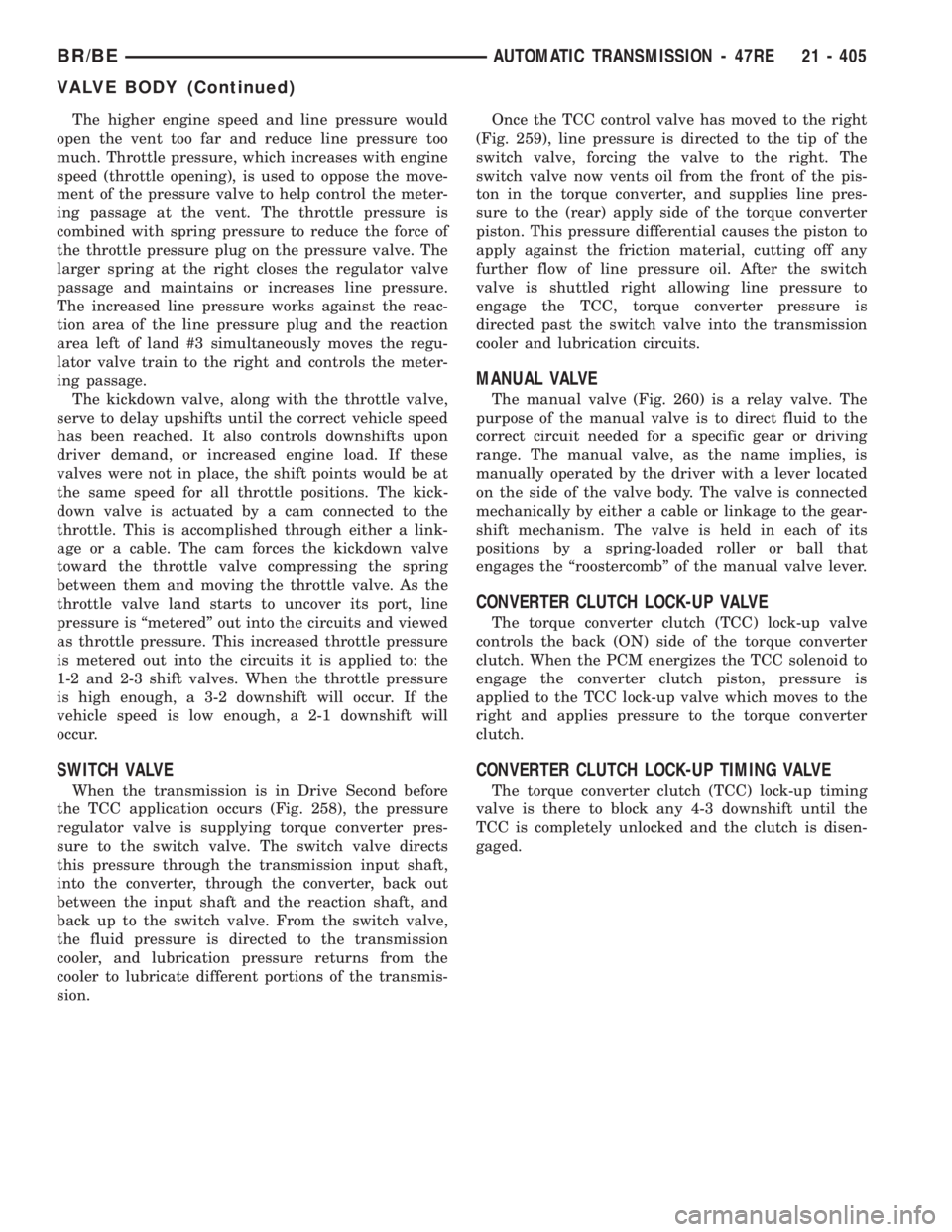
THROTTLE VALVE
In all gear positions the throttle valve (Fig. 257) is
being supplied with line pressure. The throttle valve
meters and reduces the line pressure that now
becomes throttle pressure. The throttle valve is
moved by a spring and the kickdown valve, which is
mechanically connected to the throttle. The larger
the throttle opening, the higher the throttle pressure
(to a maximum of line pressure). The smaller the
throttle opening, the lower the throttle pressure (to a
minimum of zero at idle). As engine speed increases,
the increase in pump speed increases pump output.
The increase in pressure and volume must be regu-
lated to maintain the balance within the transmis-
sion. To do this, throttle pressure is routed to the
reaction area on the right side of the throttle pres-
sure plug (in the regulator valve).
Fig. 257 Throttle Valve
Fig. 256 3-4 Shift Valve After Shift
21 - 404 AUTOMATIC TRANSMISSION - 47REBR/BE
VALVE BODY (Continued)
Page 1858 of 2255
The higher engine speed and line pressure would
open the vent too far and reduce line pressure too
much. Throttle pressure, which increases with engine
speed (throttle opening), is used to oppose the move-
ment of the pressure valve to help control the meter-
ing passage at the vent. The throttle pressure is
combined with spring pressure to reduce the force of
the throttle pressure plug on the pressure valve. The
larger spring at the right closes the regulator valve
passage and maintains or increases line pressure.
The increased line pressure works against the reac-
tion area of the line pressure plug and the reaction
area left of land #3 simultaneously moves the regu-
lator valve train to the right and controls the meter-
ing passage.
The kickdown valve, along with the throttle valve,
serve to delay upshifts until the correct vehicle speed
has been reached. It also controls downshifts upon
driver demand, or increased engine load. If these
valves were not in place, the shift points would be at
the same speed for all throttle positions. The kick-
down valve is actuated by a cam connected to the
throttle. This is accomplished through either a link-
age or a cable. The cam forces the kickdown valve
toward the throttle valve compressing the spring
between them and moving the throttle valve. As the
throttle valve land starts to uncover its port, line
pressure is ªmeteredº out into the circuits and viewed
as throttle pressure. This increased throttle pressure
is metered out into the circuits it is applied to: the
1-2 and 2-3 shift valves. When the throttle pressure
is high enough, a 3-2 downshift will occur. If the
vehicle speed is low enough, a 2-1 downshift will
occur.
SWITCH VALVE
When the transmission is in Drive Second before
the TCC application occurs (Fig. 258), the pressure
regulator valve is supplying torque converter pres-
sure to the switch valve. The switch valve directs
this pressure through the transmission input shaft,
into the converter, through the converter, back out
between the input shaft and the reaction shaft, and
back up to the switch valve. From the switch valve,
the fluid pressure is directed to the transmission
cooler, and lubrication pressure returns from the
cooler to lubricate different portions of the transmis-
sion.Once the TCC control valve has moved to the right
(Fig. 259), line pressure is directed to the tip of the
switch valve, forcing the valve to the right. The
switch valve now vents oil from the front of the pis-
ton in the torque converter, and supplies line pres-
sure to the (rear) apply side of the torque converter
piston. This pressure differential causes the piston to
apply against the friction material, cutting off any
further flow of line pressure oil. After the switch
valve is shuttled right allowing line pressure to
engage the TCC, torque converter pressure is
directed past the switch valve into the transmission
cooler and lubrication circuits.
MANUAL VALVE
The manual valve (Fig. 260) is a relay valve. The
purpose of the manual valve is to direct fluid to the
correct circuit needed for a specific gear or driving
range. The manual valve, as the name implies, is
manually operated by the driver with a lever located
on the side of the valve body. The valve is connected
mechanically by either a cable or linkage to the gear-
shift mechanism. The valve is held in each of its
positions by a spring-loaded roller or ball that
engages the ªroostercombº of the manual valve lever.
CONVERTER CLUTCH LOCK-UP VALVE
The torque converter clutch (TCC) lock-up valve
controls the back (ON) side of the torque converter
clutch. When the PCM energizes the TCC solenoid to
engage the converter clutch piston, pressure is
applied to the TCC lock-up valve which moves to the
right and applies pressure to the torque converter
clutch.
CONVERTER CLUTCH LOCK-UP TIMING VALVE
The torque converter clutch (TCC) lock-up timing
valve is there to block any 4-3 downshift until the
TCC is completely unlocked and the clutch is disen-
gaged.
BR/BEAUTOMATIC TRANSMISSION - 47RE 21 - 405
VALVE BODY (Continued)
Page 1883 of 2255
TRANSFER CASE - NV241LD
TABLE OF CONTENTS
page page
TRANSFER CASE - NV241LD
DESCRIPTION........................430
OPERATION..........................430
DIAGNOSIS AND TESTING - TRANSFER
CASE..............................431
REMOVAL............................432
DISASSEMBLY........................432
CLEANING...........................441
INSPECTION.........................442
ASSEMBLY...........................445
INSTALLATION........................458
SPECIFICATIONS
TRANSFER CASE....................458
SPECIAL TOOLS
TRANSFER CASE - NV241LD...........459EXTENSION HOUSING BUSHING AND SEAL
REMOVAL............................460
INSTALLATION........................460
FLUID
STANDARD PROCEDURE - FLUID DRAIN AND
REFILL............................460
FRONT OUTPUT SHAFT SEAL
REMOVAL............................461
INSTALLATION........................461
SHIFT LEVER
REMOVAL............................462
INSTALLATION........................462
ADJUSTMENTS
ADJUSTMENT - SHIFT LEVER..........463
TRANSFER CASE - NV241LD
DESCRIPTION
The NV241LD transfer case is a part-time transfer
case with a low-range gear system. It provides three
operating ranges plus a NEUTRAL position. The low
range position provides a gear reduction ratio of
2.72:1 for increased low speed torque capability.
The synchronizer mechanism consists of a brass
stop ring, synchro hub, and the sliding clutch. The
synchronizer components allow the transfer case to
be shifted between the 2H and 4H operating ranges
while the vehicle is in motion.
The gear cases, retainer and extension are all of
aluminum. Drive sprockets and an interconnecting
drive chain are used to transmit engine torque to the
front/rear propeller shafts. The mainshaft, input gear
and front output shaft are supported by ball and nee-
dle bearings.
IDENTIFICATION
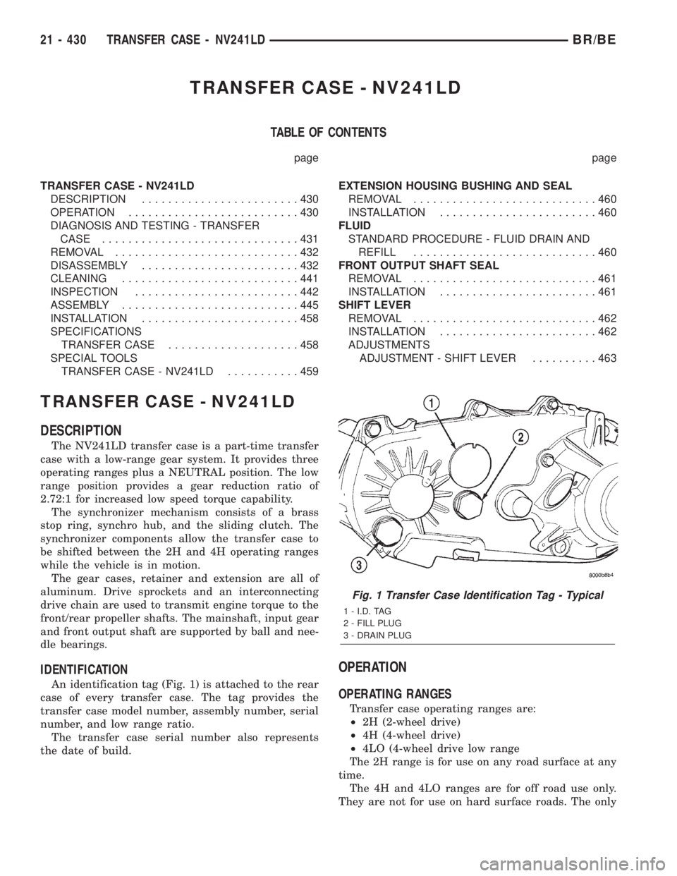
An identification tag (Fig. 1) is attached to the rear
case of every transfer case. The tag provides the
transfer case model number, assembly number, serial
number, and low range ratio.
The transfer case serial number also represents
the date of build.
OPERATION
OPERATING RANGES
Transfer case operating ranges are:
²2H (2-wheel drive)
²4H (4-wheel drive)
²4LO (4-wheel drive low range
The 2H range is for use on any road surface at any
time.
The 4H and 4LO ranges are for off road use only.
They are not for use on hard surface roads. The only
Fig. 1 Transfer Case Identification Tag - Typical
1 - I.D. TAG
2 - FILL PLUG
3 - DRAIN PLUG
21 - 430 TRANSFER CASE - NV241LDBR/BE
Page 1918 of 2255
TRANSFER CASE - NV241HD
TABLE OF CONTENTS
page page
TRANSFER CASE - NV241HD
DESCRIPTION........................465
OPERATION..........................467
DIAGNOSIS AND TESTING - TRANSFER
CASE..............................467
REMOVAL............................469
DISASSEMBLY........................469
CLEANING...........................476
INSPECTION.........................476
ASSEMBLY...........................480
INSTALLATION........................494
SPECIFICATIONS
TRANSFER CASE....................495
SPECIAL TOOLS
TRANSFER CASE - NV241HD...........495EXTENSION HOUSING BUSHING AND SEAL
REMOVAL............................497
INSTALLATION........................497
FLUID
STANDARD PROCEDURE - FLUID DRAIN/
REFILL............................497
FRONT OUTPUT SHAFT SEAL
REMOVAL............................498
INSTALLATION........................498
SHIFT LEVER
REMOVAL............................499
INSTALLATION........................500
ADJUSTMENTS
ADJUSTMENT - SHIFT LEVER..........500
TRANSFER CASE - NV241HD
DESCRIPTION
The NV241HD is a part-time transfer case with a
low-range gear system. The transfer case provides
three operating ranges plus a NEUTRAL position.
The low range position provides a gear reduction
ratio of 2.72:1 for increased low speed torque capabil-
ity. Operating ranges are: 2H, 4H, and 4LO.
The synchronizer mechanism consists of a brass
stop ring, synchronizer hub, and the sliding clutch
(Fig. 1). The synchronizer components allow the
transfer case to be shifted between the 2H and 4H
operating ranges while the vehicle is in motion.The gear cases, retainer and extension are all of
aluminum. Drive sprockets and an interconnecting
drive chain are used to transmit engine torque to the
front/rear propeller shafts. The mainshaft, input gear
and front output shaft are supported by ball and nee-
dle bearings.
PTO CAPABILITY
The NV241HD transfer case has power take-off
capability. A PTO gear permanently attached to the
planetary carrier, and a removable PTO cover are
provided for this purpose.
BR/BETRANSFER CASE - NV241HD 21 - 465
Page 1961 of 2255
TIRES
DESCRIPTION
DESCRIPTION - SPARE TIRE - TEMPORARY
The temporary spare tire is designed for emer-
gency use only. The original tire should be repaired
or replaced at the first opportunity, then reinstalled.
Do not exceed speeds of 50 M.P.H. when using the
temporary spare tire. Refer to Owner's Manual for
complete details.
DESCRIPTION - TIRES
Tires are designed and engineered for each specific
vehicle. They provide the best overall performance
for normal operation. The ride and handling charac-
teristics match the vehicle's requirements. With
proper care they will give excellent reliability, trac-
tion, skid resistance, and tread life.
Driving habits have more effect on tire life than
any other factor. Careful drivers will obtain in most
cases, much greater mileage than severe use or care-
less drivers. A few of the driving habits which will
shorten the life of any tire are:
²Rapid acceleration
²Severe brake applications
²High speed driving
²Excessive speeds on turns
²Striking curbs and other obstacles
Radial-ply tires are more prone to irregular tread
wear. It is important to follow the tire rotation inter-
val shown in the section on Tire Rotation, (Refer to
22 - TIRES/WHEELS - STANDARD PROCEDURE).
This will help to achieve a greater tread life.
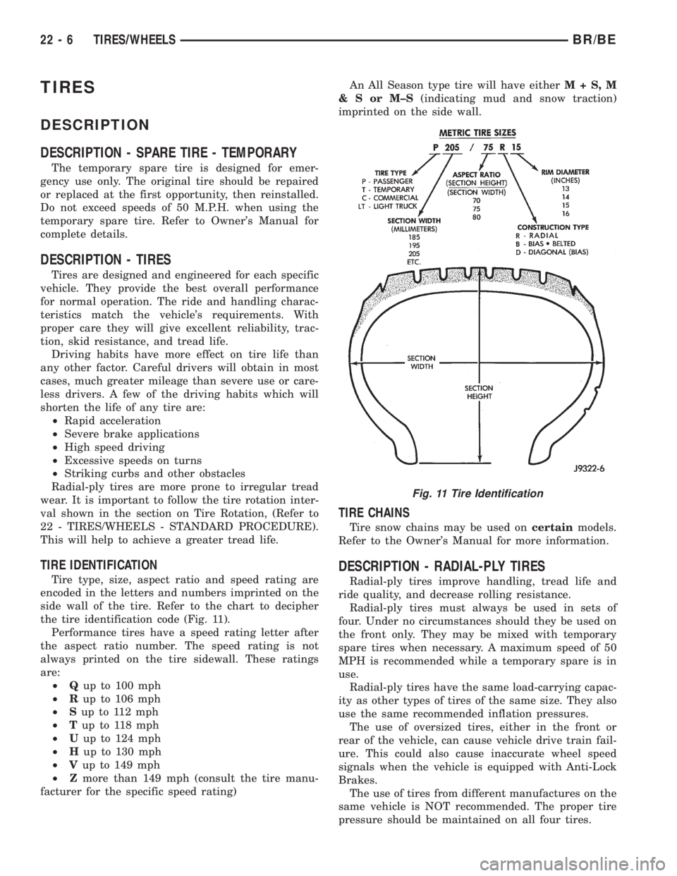
TIRE IDENTIFICATION
Tire type, size, aspect ratio and speed rating are
encoded in the letters and numbers imprinted on the
side wall of the tire. Refer to the chart to decipher
the tire identification code (Fig. 11).
Performance tires have a speed rating letter after
the aspect ratio number. The speed rating is not
always printed on the tire sidewall. These ratings
are:
²Qup to 100 mph
²Rup to 106 mph
²Sup to 112 mph
²Tup to 118 mph
²Uup to 124 mph
²Hup to 130 mph
²Vup to 149 mph
²Zmore than 149 mph (consult the tire manu-
facturer for the specific speed rating)An All Season type tire will have eitherM+S,M
&SorM±S(indicating mud and snow traction)
imprinted on the side wall.
TIRE CHAINS
Tire snow chains may be used oncertainmodels.
Refer to the Owner's Manual for more information.
DESCRIPTION - RADIAL-PLY TIRES
Radial-ply tires improve handling, tread life and
ride quality, and decrease rolling resistance.
Radial-ply tires must always be used in sets of
four. Under no circumstances should they be used on
the front only. They may be mixed with temporary
spare tires when necessary. A maximum speed of 50
MPH is recommended while a temporary spare is in
use.
Radial-ply tires have the same load-carrying capac-
ity as other types of tires of the same size. They also
use the same recommended inflation pressures.
The use of oversized tires, either in the front or
rear of the vehicle, can cause vehicle drive train fail-
ure. This could also cause inaccurate wheel speed
signals when the vehicle is equipped with Anti-Lock
Brakes.
The use of tires from different manufactures on the
same vehicle is NOT recommended. The proper tire
pressure should be maintained on all four tires.
Fig. 11 Tire Identification
22 - 6 TIRES/WHEELSBR/BE
Page 1964 of 2255
DIAGNOSIS AND TESTING - TIRE NOISE OR
VIBRATION
Radial-ply tires are sensitive to force impulses
caused by improper mounting, vibration, wheel
defects, or possibly tire imbalance.
To find out if tires are causing the noise or vibra-
tion, drive the vehicle over a smooth road at varying
speeds. Note the noise level during acceleration and
deceleration. The engine, differential and exhaust
noises will change as speed varies, while the tire
noise will usually remain constant.
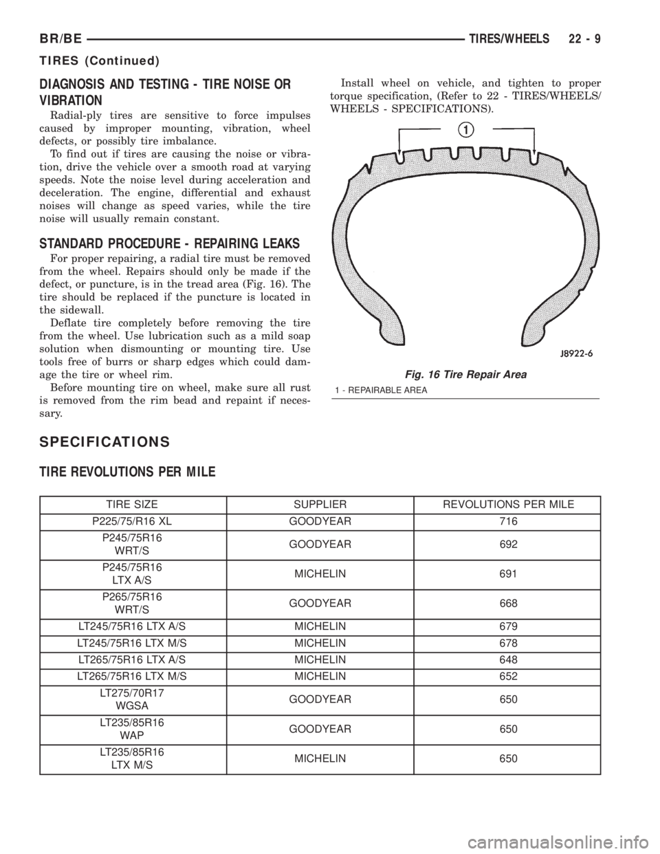
STANDARD PROCEDURE - REPAIRING LEAKS
For proper repairing, a radial tire must be removed
from the wheel. Repairs should only be made if the
defect, or puncture, is in the tread area (Fig. 16). The
tire should be replaced if the puncture is located in
the sidewall.
Deflate tire completely before removing the tire
from the wheel. Use lubrication such as a mild soap
solution when dismounting or mounting tire. Use
tools free of burrs or sharp edges which could dam-
age the tire or wheel rim.
Before mounting tire on wheel, make sure all rust
is removed from the rim bead and repaint if neces-
sary.Install wheel on vehicle, and tighten to proper
torque specification, (Refer to 22 - TIRES/WHEELS/
WHEELS - SPECIFICATIONS).
SPECIFICATIONS
TIRE REVOLUTIONS PER MILE
TIRE SIZE SUPPLIER REVOLUTIONS PER MILE
P225/75/R16 XL GOODYEAR 716
P245/75R16
WRT/SGOODYEAR 692
P245/75R16
LTX A/SMICHELIN 691
P265/75R16
WRT/SGOODYEAR 668
LT245/75R16 LTX A/S MICHELIN 679
LT245/75R16 LTX M/S MICHELIN 678
LT265/75R16 LTX A/S MICHELIN 648
LT265/75R16 LTX M/S MICHELIN 652
LT275/70R17
WGSAGOODYEAR 650
LT235/85R16
WAPGOODYEAR 650
LT235/85R16
LTX M/SMICHELIN 650
Fig. 16 Tire Repair Area
1 - REPAIRABLE AREA
BR/BETIRES/WHEELS 22 - 9
TIRES (Continued)