Battery cables DODGE RAM 2002 Service Repair Manual
[x] Cancel search | Manufacturer: DODGE, Model Year: 2002, Model line: RAM, Model: DODGE RAM 2002Pages: 2255, PDF Size: 62.07 MB
Page 21 of 2255
TO JUMP START A DISABLED VEHICLE:
(1) Raise hood on disabled vehicle and visually
inspect engine compartment for:
²Battery cable clamp condition, clean if necessary.
²Frozen battery.
²Yellow or bright color test indicator, if equipped.
²Low battery fluid level.
²Generator drive belt condition and tension.
²Fuel fumes or leakage, correct if necessary.
CAUTION: If the cause of starting problem on dis-
abled vehicle is severe, damage to booster vehicle
charging system can result.
(2) When using another vehicle as a booster
source, park the booster vehicle within cable reach.
Turn off all accessories, set the parking brake, place
the automatic transmission in PARK or the manual
transmission in NEUTRAL and turn the ignition
OFF.
(3) On disabled vehicle, place gear selector in park
or neutral and set park brake. Turn off all accesso-
ries.
(4) Connect jumper cables to booster battery. RED
clamp to positive terminal (+). BLACK clamp to neg-
ative terminal (-). DO NOT allow clamps at opposite
end of cables to touch, electrical arc will result.
Review all warnings in this procedure.
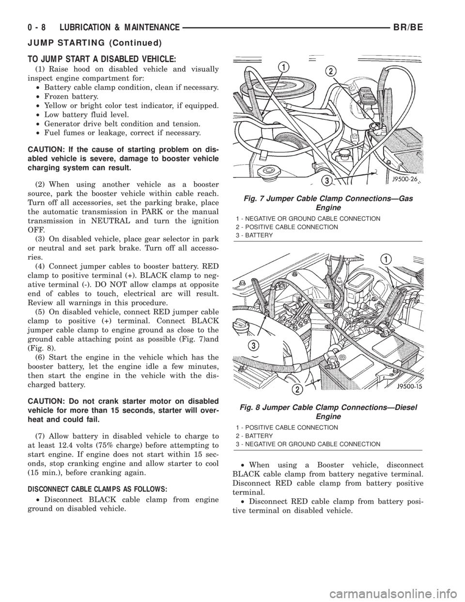
(5) On disabled vehicle, connect RED jumper cable
clamp to positive (+) terminal. Connect BLACK
jumper cable clamp to engine ground as close to the
ground cable attaching point as possible (Fig. 7)and
(Fig. 8).
(6) Start the engine in the vehicle which has the
booster battery, let the engine idle a few minutes,
then start the engine in the vehicle with the dis-
charged battery.
CAUTION: Do not crank starter motor on disabled
vehicle for more than 15 seconds, starter will over-
heat and could fail.
(7) Allow battery in disabled vehicle to charge to
at least 12.4 volts (75% charge) before attempting to
start engine. If engine does not start within 15 sec-
onds, stop cranking engine and allow starter to cool
(15 min.), before cranking again.
DISCONNECT CABLE CLAMPS AS FOLLOWS:
²Disconnect BLACK cable clamp from engine
ground on disabled vehicle.²When using a Booster vehicle, disconnect
BLACK cable clamp from battery negative terminal.
Disconnect RED cable clamp from battery positive
terminal.
²Disconnect RED cable clamp from battery posi-
tive terminal on disabled vehicle.
Fig. 7 Jumper Cable Clamp ConnectionsÐGas
Engine
1 - NEGATIVE OR GROUND CABLE CONNECTION
2 - POSITIVE CABLE CONNECTION
3 - BATTERY
Fig. 8 Jumper Cable Clamp ConnectionsÐDiesel
Engine
1 - POSITIVE CABLE CONNECTION
2 - BATTERY
3 - NEGATIVE OR GROUND CABLE CONNECTION
0 - 8 LUBRICATION & MAINTENANCEBR/BE
JUMP STARTING (Continued)
Page 225 of 2255
OPERATION
Battery voltage is supplied to the CAB when a
speed of 15 miles per hour is reached. The CAB per-
forms a system initialization procedure at this point.
Initialization consists of a static and dynamic self
check of system electrical components.
The static and dynamic checks occurs at ignition
start up. During the dynamic check, the CAB briefly
cycles the pump and solenoids to verify operation. An
audible noise may be heard during this self check.
This noise should be considered normal.
If an ABS component exhibits a fault during ini-
tialization, the CAB illuminates the amber warning
light and registers a fault code in the microprocessor
memory.
The CAB monitors wheel speed sensor inputs con-
tinuously while the vehicle is in motion. However,
the CAB will not activate any ABS components as
long as sensor inputs indicate normal braking.
During normal braking, the master cylinder, power
booster and wheel brake units all function as they
would in a vehicle without ABS. The HCU compo-
nents are not activated.
The purpose of the antilock system is to prevent
wheel lockup during periods of high wheel slip. Pre-
venting lockup helps maintain vehicle braking action
and steering control.
The antilock CAB activates the system whenever
sensor signals indicate periods of wheel slip. Periods
of wheel slip occur when brake stops involve high
pedal pressure and rate of vehicle deceleration.
The antilock system prevents lockup during a
wheel slip condition by modulating fluid apply pres-
sure to the wheel brake units.
Brake fluid apply pressure is modulated according
to wheel speed, degree of slip and rate of decelera-
tion. Sensors at each front wheel convert wheel speed
into electrical signals. These signals are transmitted
to the CAB for processing and determination of
wheel slip and deceleration rate.
The ABS system has three fluid pressure control
channels. The front brakes are controlled separately
and the rear brakes in tandem. A speed sensor input
signal indicating a wheel slip condition activates the
CAB antilock program.
There are Two solenoid valves (Isolation and Dump
valve) which are used in each antilock control chan-
nel. The valves are all located within the HCU valve
body and work in pairs to either increase, hold, or
decrease apply pressure as needed in the individual
control channels.
During an ABS stop the ISO valve actuates, Stop-
ping anymore pressure build Ðup to the calipers.
Then the Dump valve dumps off pressure until the
wheel unlocks. This will continue until the wheels
quit slipping altogether.
DIAGNOSIS AND TESTING - ANTILOCK
BRAKES
The ABS brake system performs several self-tests
every time the ignition switch is turned on and the
vehicle is driven. The CAB monitors the systems
input and output circuits to verify the system is oper-
ating correctly. If the on board diagnostic system
senses that a circuit is malfunctioning the system
will set a trouble code in its memory.
NOTE: An audible noise may be heard during the
self-test. This noise should be considered normal.
NOTE: The MDS or DRB III scan tool is used to
diagnose the ABS system. For additional informa-
tion refer to the Antilock Brake section in Group
8W. For test procedures refer to the Chassis Diag-
nostic Manual.
STANDARD PROCEDURE
STANDARD PROCEDURE - RWAL SERVICE
PRECAUTIONS
The RWAL uses an electronic control module, the
CAB. This module is designed to withstand normal
current draws associated with vehicle operation.
Care must be taken to avoid overloading the CAB
circuits.In testing for open or short circuits, do
not ground or apply voltage to any of the cir-
cuits unless instructed to do so for a diagnostic
procedure.These circuits should only be tested
using a high impedance multi-meter or the DRB
tester as described in this section. Power should
never be removed or applied to any control module
with the ignition in the ON position. Before removing
or connecting battery cables, fuses, or connectors,
always turn the ignition to the OFF position.
CAUTION: Use only factory wiring harnesses. Do
not cut or splice wiring to the brake circuits. The
addition of after-market electrical equipment (car
phone, radar detector, citizen band radio, trailer
lighting, trailer brakes, ect.) on a vehicle equipped
with antilock brakes may affect the function of the
antilock brake system.
STANDARD PROCEDURE - BLEEDING ABS
BRAKE SYSTEM
ABS system bleeding requires conventional bleed-
ing methods plus use of the DRB scan tool. The pro-
cedure involves performing a base brake bleeding,
followed by use of the scan tool to cycle and bleed the
5 - 36 BRAKES - ABSBR/BE
BRAKES - ABS (Continued)
Page 283 of 2255
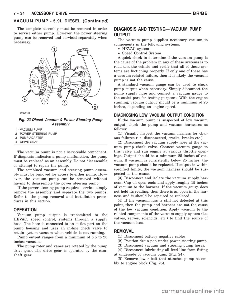
The complete assembly must be removed in order
to service either pump. However, the power steering
pump can be removed and serviced separately when
necessary.
The vacuum pump is not a serviceable component.
If diagnosis indicates a pump malfunction, the pump
must be replaced as an assembly. Do not disassemble
or attempt to repair the pump.
The combined vacuum and steering pump assem-
bly must be removed for access to either pump. How-
ever, the vacuum pump can be removed without
having to disassemble the power steering pump.
If the power steering pump requires service, simply
remove the assembly and separate the two pumps.
Refer to the pump removal and installation proce-
dures in this section.
OPERATION
Vacuum pump output is transmitted to the
HEVAC, speed control, systems through a supply
hose. The hose is connected to an outlet port on the
pump housing and uses an in-line check valve to
retain system vacuum when vehicle is not running.
Pump output ranges from a minimum of 8.5 to 25
inches vacuum.
The pump rotor and vanes are rotated by the pump
drive gear. The drive gear is operated by the cam-
shaft gear.
DIAGNOSIS AND TESTINGÐVACUUM PUMP
OUTPUT
The vacuum pump supplies necessary vacuum to
components in the following systems:
²HEVAC system
²Speed Control System
A quick check to determine if the vacuum pump is
the cause of the problem in any of these systems is to
road test the vehicle and verify that all of these sys-
tems are fuctioning properly. If only one of these has
a vacuum related failure, then it is likely the vacuum
pump is not the cause.
A standard vacuum gauge can be used to check
pump output when necessary. Simply disconnect the
pump supply hose and connect a vacuum gauge to
the outlet port for testing purposes. With the engine
running, vacuum output should be a minimum of 25
inches, depending on engine speed.
DIAGNOSING LOW VACUUM OUTPUT CONDITION
If the vacuum pump is suspected of low vacuum
output, check the pump and vacuum harnesses as
follows:
(1) Visually inspect the vacuum harness for obvi-
ous failures (i.e. disconnected, cracks, breaks etc.)
(2) Disconnect the vacuum supply hose at the vac-
uum pump check valve. Connect vacuum gauge to
this valve and run engine at various throttle open-
ings. Output should be a minimum 25 inches of vac-
uum. If vacuum is consistently below 25 inches, the
vacuum pump should be replaced. If output is within
specified limits, the vacuum harness should be sus-
pected as the cause.
(3) Disconnect and isolate the vacuum supply har-
ness. Cap off open ends and apply roughly 15 inches
of vacuum to the harness. If the vacuum gauge does
not hold its reading, then there is an open in the har-
ness and it should be repaired or replaced.
(4) If the vacuum loss is still not detected at this
point, then the pump and harness are not the cause
of the low vacuum condition. Apply vacuum to the
related components of the vacuum supply system (i.e.
valves, servos, solenoids, etc.) to find the source of
the vacuum loss.
REMOVAL
(1) Disconnect battery negative cables.
(2) Position drain pan under power steering pump.
(3) Disconnect vacuum and steering pump hoses.
(4) Disconnect lubricating oil feed line from fitting
at underside of vacuum pump (Fig. 24).
(5) Remove lower bolt that attaches pump assem-
bly to engine block (Fig. 25).
Fig. 23 Diesel Vacuum & Power Steering Pump
Assembly
1 - VACUUM PUMP
2 - POWER STEERING PUMP
3 - PUMP ADAPTER
4 - DRIVE GEAR
7 - 34 ACCESSORY DRIVEBR/BE
VACUUM PUMP - 5.9L DIESEL (Continued)
Page 286 of 2255
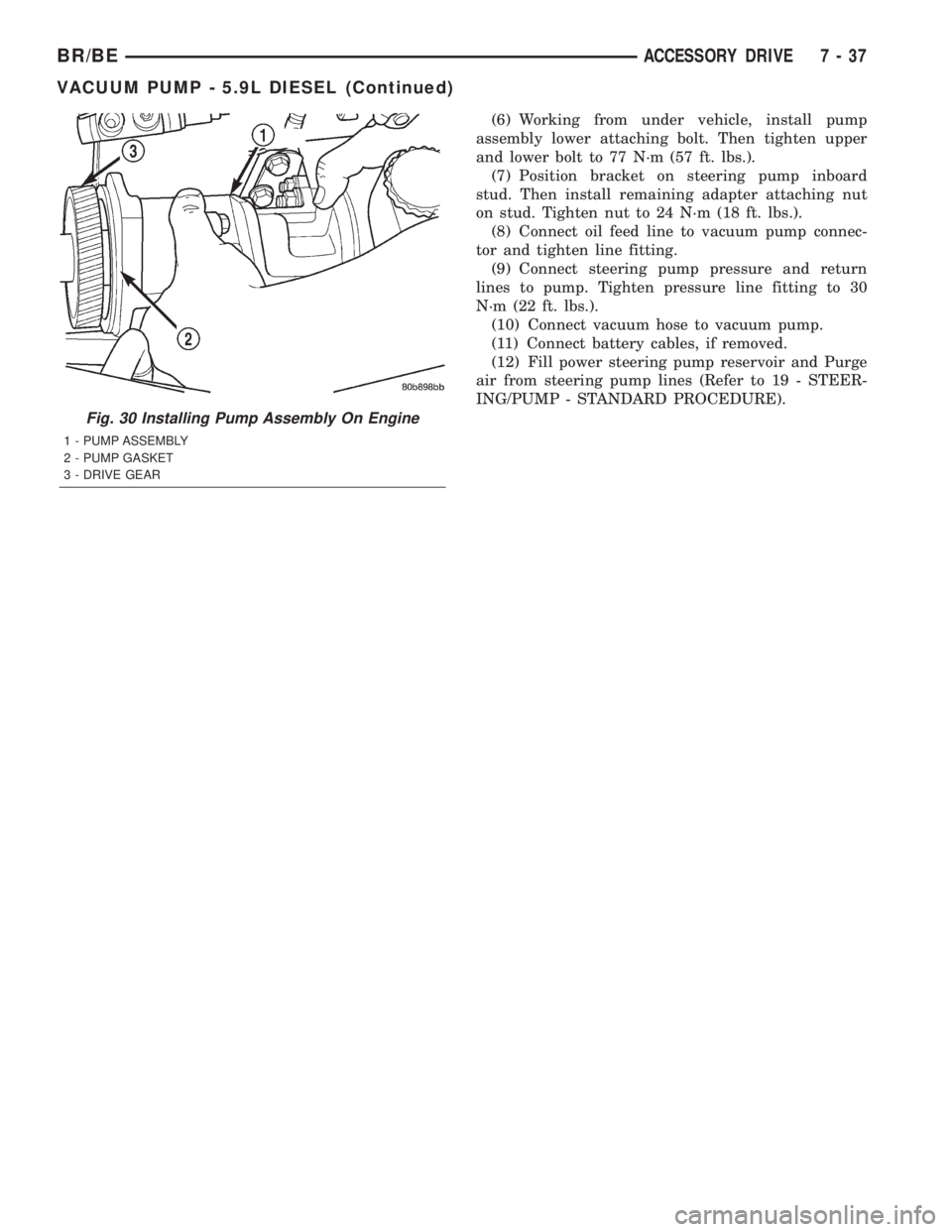
(6) Working from under vehicle, install pump
assembly lower attaching bolt. Then tighten upper
and lower bolt to 77 N´m (57 ft. lbs.).
(7) Position bracket on steering pump inboard
stud. Then install remaining adapter attaching nut
on stud. Tighten nut to 24 N´m (18 ft. lbs.).
(8) Connect oil feed line to vacuum pump connec-
tor and tighten line fitting.
(9) Connect steering pump pressure and return
lines to pump. Tighten pressure line fitting to 30
N´m (22 ft. lbs.).
(10) Connect vacuum hose to vacuum pump.
(11) Connect battery cables, if removed.
(12) Fill power steering pump reservoir and Purge
air from steering pump lines (Refer to 19 - STEER-
ING/PUMP - STANDARD PROCEDURE).
Fig. 30 Installing Pump Assembly On Engine
1 - PUMP ASSEMBLY
2 - PUMP GASKET
3 - DRIVE GEAR
BR/BEACCESSORY DRIVE 7 - 37
VACUUM PUMP - 5.9L DIESEL (Continued)
Page 292 of 2255
(4) Install fan blade/viscous fan drive assembly to
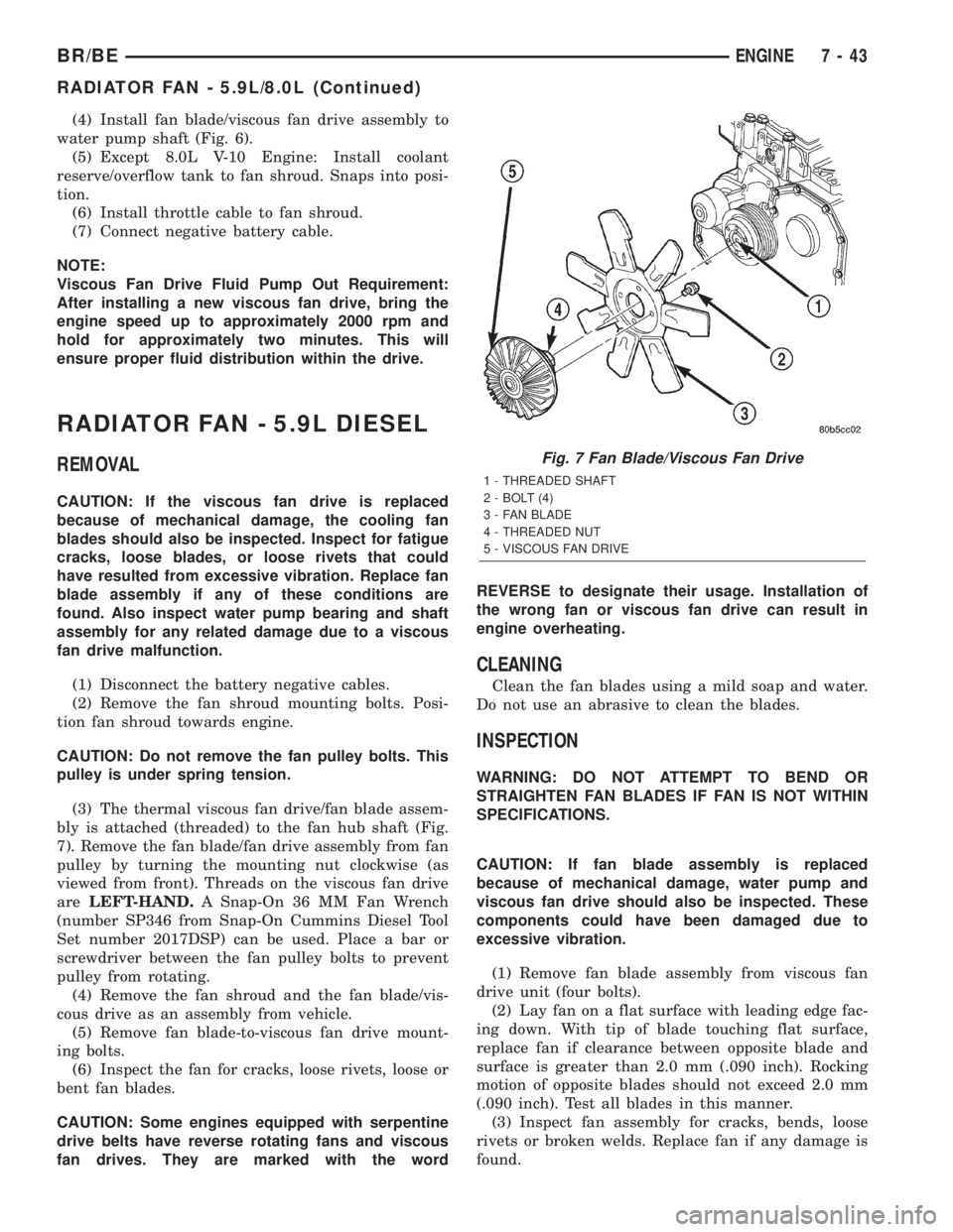
water pump shaft (Fig. 6).
(5) Except 8.0L V-10 Engine: Install coolant
reserve/overflow tank to fan shroud. Snaps into posi-
tion.
(6) Install throttle cable to fan shroud.
(7) Connect negative battery cable.
NOTE:
Viscous Fan Drive Fluid Pump Out Requirement:
After installing a new viscous fan drive, bring the
engine speed up to approximately 2000 rpm and
hold for approximately two minutes. This will
ensure proper fluid distribution within the drive.
RADIATOR FAN - 5.9L DIESEL
REMOVAL
CAUTION: If the viscous fan drive is replaced
because of mechanical damage, the cooling fan
blades should also be inspected. Inspect for fatigue
cracks, loose blades, or loose rivets that could
have resulted from excessive vibration. Replace fan
blade assembly if any of these conditions are
found. Also inspect water pump bearing and shaft
assembly for any related damage due to a viscous
fan drive malfunction.
(1) Disconnect the battery negative cables.
(2) Remove the fan shroud mounting bolts. Posi-
tion fan shroud towards engine.
CAUTION: Do not remove the fan pulley bolts. This
pulley is under spring tension.
(3) The thermal viscous fan drive/fan blade assem-
bly is attached (threaded) to the fan hub shaft (Fig.
7). Remove the fan blade/fan drive assembly from fan
pulley by turning the mounting nut clockwise (as
viewed from front). Threads on the viscous fan drive
areLEFT-HAND.A Snap-On 36 MM Fan Wrench
(number SP346 from Snap-On Cummins Diesel Tool
Set number 2017DSP) can be used. Place a bar or
screwdriver between the fan pulley bolts to prevent
pulley from rotating.
(4) Remove the fan shroud and the fan blade/vis-
cous drive as an assembly from vehicle.
(5) Remove fan blade-to-viscous fan drive mount-
ing bolts.
(6) Inspect the fan for cracks, loose rivets, loose or
bent fan blades.
CAUTION: Some engines equipped with serpentine
drive belts have reverse rotating fans and viscous
fan drives. They are marked with the wordREVERSE to designate their usage. Installation of
the wrong fan or viscous fan drive can result in
engine overheating.
CLEANING
Clean the fan blades using a mild soap and water.
Do not use an abrasive to clean the blades.
INSPECTION
WARNING: DO NOT ATTEMPT TO BEND OR
STRAIGHTEN FAN BLADES IF FAN IS NOT WITHIN
SPECIFICATIONS.
CAUTION: If fan blade assembly is replaced
because of mechanical damage, water pump and
viscous fan drive should also be inspected. These
components could have been damaged due to
excessive vibration.
(1) Remove fan blade assembly from viscous fan
drive unit (four bolts).
(2) Lay fan on a flat surface with leading edge fac-
ing down. With tip of blade touching flat surface,
replace fan if clearance between opposite blade and
surface is greater than 2.0 mm (.090 inch). Rocking
motion of opposite blades should not exceed 2.0 mm
(.090 inch). Test all blades in this manner.
(3) Inspect fan assembly for cracks, bends, loose
rivets or broken welds. Replace fan if any damage is
found.
Fig. 7 Fan Blade/Viscous Fan Drive
1 - THREADED SHAFT
2 - BOLT (4)
3 - FAN BLADE
4 - THREADED NUT
5 - VISCOUS FAN DRIVE
BR/BEENGINE 7 - 43
RADIATOR FAN - 5.9L/8.0L (Continued)
Page 293 of 2255
INSTALLATION
(1) Install fan blade assembly to viscous fan drive.
Tighten mounting bolts to 23 N´m (17 ft. lbs.) torque.
(2) Position the fan shroud and fan blade/viscous
fan drive to the vehicle as an assembly.
(3) Install viscous fan drive assembly on fan hub
shaft (Fig. 7). Tighten mounting nut to 57 N´m (42 ft.
lbs.) torque.
(4) Install fan shroud bolts into position and
tighten the mounting bolts to 6 N´m (50 in. lbs.)
torque.
(5) Connect the battery negative cables.
NOTE:
Viscous Fan Drive Fluid Pump Out Requirement:
After installing a new viscous fan drive, bring the
engine speed up to approximately 2000 rpm and
hold for approximately two minutes. This will
ensure proper fluid distribution within the drive.
ENGINE BLOCK HEATER - 5.9L
DESCRIPTION
WARNING: DO NOT OPERATE ENGINE UNLESS
BLOCK HEATER CORD HAS BEEN DISCONNECTED
FROM POWER SOURCE AND SECURED IN PLACE.
THE POWER CORD MUST BE SECURED IN ITS
RETAINING CLIPS AND ROUTED AWAY FROM
EXHAUST MANIFOLDS AND MOVING PARTS.
An optional engine block heater is available on all
models. The heater is equipped with a power cord.
The heater is mounted in a core hole of the engine
cylinder block (in place of a freeze plug) with the
heating element immersed in engine coolant. The
cord is attached to an engine compartment compo-
nent with tie-straps.
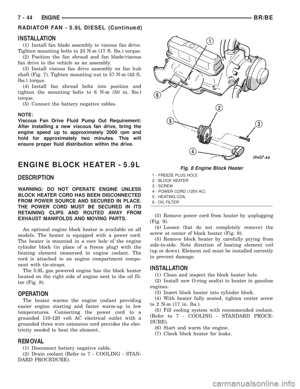
The 5.9L gas powered engine has the block heater
located on the right side of engine next to the oil fil-
ter (Fig. 8).
OPERATION
The heater warms the engine coolant providing
easier engine starting and faster warm-up in low
temperatures. Connecting the power cord to a
grounded 110-120 volt AC electrical outlet with a
grounded three wire extension cord provides the elec-
tricity needed to heat the element..
REMOVAL
(1) Disconnect battery negative cable.
(2) Drain coolant (Refer to 7 - COOLING - STAN-
DARD PROCEDURE).(3) Remove power cord from heater by unplugging
(Fig. 9).
(4) Loosen (but do not completely remove) the
screw at center of block heater (Fig. 9).
(5) Remove block heater by carefully prying from
side-to-side. Note direction of heating element coil
(up or down). Element coil must be installed correctly
to prevent damage.
INSTALLATION
(1) Clean and inspect the block heater hole.
(2) Install new O-ring seal(s) to heater in gasoline
engines.
(3) Insert block heater into cylinder block.
(4) With heater fully seated, tighten center screw
to 2 N´m (17 in. lbs.).
(5) Fill cooling system with recommended coolant.
(Refer to 7 - COOLING - STANDARD PROCE-
DURE).
(6) Start and warm the engine.
(7) Check block heater for leaks.
Fig. 8 Engine Block Heater
1 - FREEZE PLUG HOLE
2 - BLOCK HEATER
3 - SCREW
4 - POWER CORD (120V AC)
5 - HEATING COIL
6 - OIL FILTER
7 - 44 ENGINEBR/BE
RADIATOR FAN - 5.9L DIESEL (Continued)
Page 295 of 2255
(5) Fill cooling system with recommended coolant
(Refer to 7 - COOLING - STANDARD PROCE-
DURE).
(6) Start and warm the engine.
(7) Check block heater for leaks.
ENGINE BLOCK HEATER - 5.9L
DIESEL
DESCRIPTION
WARNING: DO NOT OPERATE ENGINE UNLESS
BLOCK HEATER CORD HAS BEEN DISCONNECTED
FROM POWER SOURCE AND SECURED IN PLACE.
THE POWER CORD MUST BE SECURED IN ITS
RETAINING CLIPS AND ROUTED AWAY FROM
EXHAUST MANIFOLDS AND MOVING PARTS.
An optional engine block heater is available on all
models. The heater is equipped with a power cord.
The heater is mounted in a threaded hole of the
engine cylinder block with the heating element
immersed in engine coolant. The cord is attached to
an engine compartment component with tie-straps.The 5.9L diesel engine has the block heater located
on the right side of the engine below the exhaust
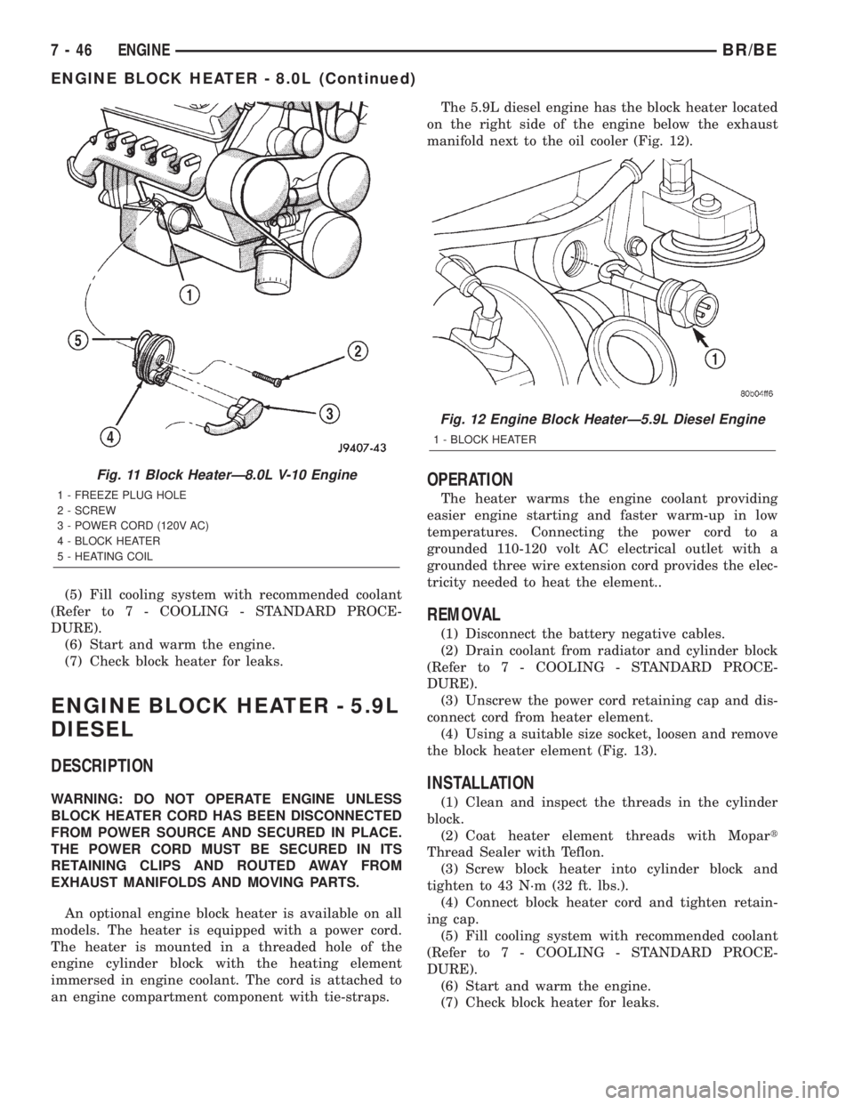
manifold next to the oil cooler (Fig. 12).
OPERATION
The heater warms the engine coolant providing
easier engine starting and faster warm-up in low
temperatures. Connecting the power cord to a
grounded 110-120 volt AC electrical outlet with a
grounded three wire extension cord provides the elec-
tricity needed to heat the element..
REMOVAL
(1) Disconnect the battery negative cables.
(2) Drain coolant from radiator and cylinder block
(Refer to 7 - COOLING - STANDARD PROCE-
DURE).
(3) Unscrew the power cord retaining cap and dis-
connect cord from heater element.
(4) Using a suitable size socket, loosen and remove
the block heater element (Fig. 13).
INSTALLATION
(1) Clean and inspect the threads in the cylinder
block.
(2) Coat heater element threads with Mopart
Thread Sealer with Teflon.
(3) Screw block heater into cylinder block and
tighten to 43 N´m (32 ft. lbs.).
(4) Connect block heater cord and tighten retain-
ing cap.
(5) Fill cooling system with recommended coolant
(Refer to 7 - COOLING - STANDARD PROCE-
DURE).
(6) Start and warm the engine.
(7) Check block heater for leaks.
Fig. 11 Block HeaterÐ8.0L V-10 Engine
1 - FREEZE PLUG HOLE
2 - SCREW
3 - POWER CORD (120V AC)
4 - BLOCK HEATER
5 - HEATING COIL
Fig. 12 Engine Block HeaterÐ5.9L Diesel Engine
1 - BLOCK HEATER
7 - 46 ENGINEBR/BE
ENGINE BLOCK HEATER - 8.0L (Continued)
Page 303 of 2255
(1) To determine if the thermostat is defective, it
must be removed from the vehicle (Refer to 7 -
COOLING/ENGINE/ENGINE COOLANT THERMO-
STAT - REMOVAL).
(2) After the thermostat has been removed, exam-
ine the thermostat and inside of thermostat housing
for contaminants. If contaminants are found, the
thermostat may already be in a ªstuck openº position.
Flush the cooling system before replacing thermostat
(Refer to 7 - COOLING - STANDARD PROCE-
DURE).
(3) Place the thermostat into a container filled
with water.
(4) Place the container on a hot plate or other suit-
able heating device.
(5) Place a commercially available radiator ther-
mometer into the water.
(6) Apply heat to the water while observing the
thermostat and thermometer.
(7) When the water temperature reaches 83ÉC
(181ÉF) the thermostat should start to open (valve
will start to move). If the valve starts to move before
this temperature is reached, it is opening too early.
Replace thermostat. The thermostat should be fully
open (valve will stop moving) at 95ÉC (203ÉF). If the
valve is still moving when the water temperature
reaches 203É, it is opening too late. Replace thermo-
stat. If the valve refuses to move at any time, replace
thermostat.
REMOVAL
WARNING: DO NOT LOOSEN THE RADIATOR
DRAINCOCK WITH THE SYSTEM HOT AND PRES-
SURIZED. SERIOUS BURNS FROM THE COOLANT
CAN OCCUR.
Do not waste reusable coolant. If the solution is
clean, drain the coolant into a clean container for
reuse.
(1) Disconnect the battery negative cables.
(2) Drain cooling system until coolant level is
below thermostat (Refer to 7 - COOLING - STAN-
DARD PROCEDURE).
WARNING: CONSTANT TENSION HOSE CLAMPS
ARE USED ON MOST COOLING SYSTEM HOSES.
WHEN REMOVING OR INSTALLING, USE ONLY
TOOLS DESIGNED FOR SERVICING THIS TYPE OF
CLAMP, SUCH AS SPECIAL CLAMP TOOL (NUMBER
6094). SNAP-ON CLAMP TOOL (NUMBER HPC-20)
MAY BE USED FOR LARGER CLAMPS. ALWAYS
WEAR SAFETY GLASSES WHEN SERVICING CON-
STANT TENSION CLAMPS.CAUTION: A number or letter is stamped into the
tongue of constant tension clamps. If replacement
is necessary, use only an original equipment clamp
with a matching number or letter.
(3) Remove radiator hose clamp and hose from
thermostat housing.
(4) Remove the three (3) water outlet-to-cylinder
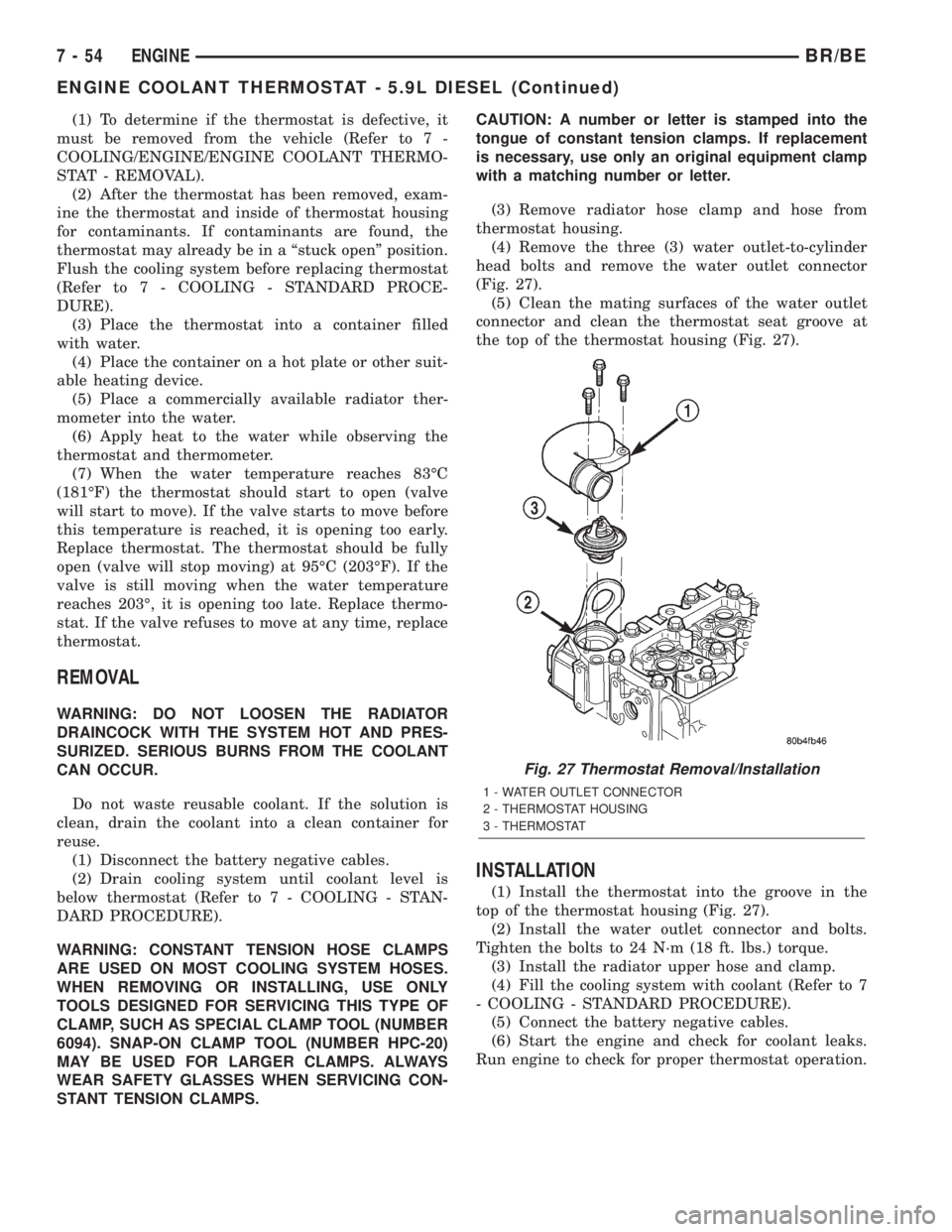
head bolts and remove the water outlet connector
(Fig. 27).
(5) Clean the mating surfaces of the water outlet
connector and clean the thermostat seat groove at
the top of the thermostat housing (Fig. 27).
INSTALLATION
(1) Install the thermostat into the groove in the
top of the thermostat housing (Fig. 27).
(2) Install the water outlet connector and bolts.
Tighten the bolts to 24 N´m (18 ft. lbs.) torque.
(3) Install the radiator upper hose and clamp.
(4) Fill the cooling system with coolant (Refer to 7
- COOLING - STANDARD PROCEDURE).
(5) Connect the battery negative cables.
(6) Start the engine and check for coolant leaks.
Run engine to check for proper thermostat operation.
Fig. 27 Thermostat Removal/Installation
1 - WATER OUTLET CONNECTOR
2 - THERMOSTAT HOUSING
3 - THERMOSTAT
7 - 54 ENGINEBR/BE
ENGINE COOLANT THERMOSTAT - 5.9L DIESEL (Continued)
Page 307 of 2255
CAUTION: Some engines equipped with serpentine
drive belts have reverse rotating fans and viscous
fan drives. They are marked with the word
REVERSE to designate their usage. Installation of
the wrong fan or viscous fan drive can result in
engine overheating.
CAUTION: If the viscous fan drive is replaced
because of mechanical damage, the cooling fan
blades should also be inspected. Inspect for fatigue
cracks, loose blades, or loose rivets that could
have resulted from excessive vibration. Replace fan
blade assembly if any of these conditions are
found. Also inspect water pump bearing and shaft
assembly for any related damage due to a viscous
fan drive malfunction.
RADIATOR - 5.9L
DESCRIPTION
The radiator is a aluminum cross-flow design with
horizontal tubes through the radiator core and verti-
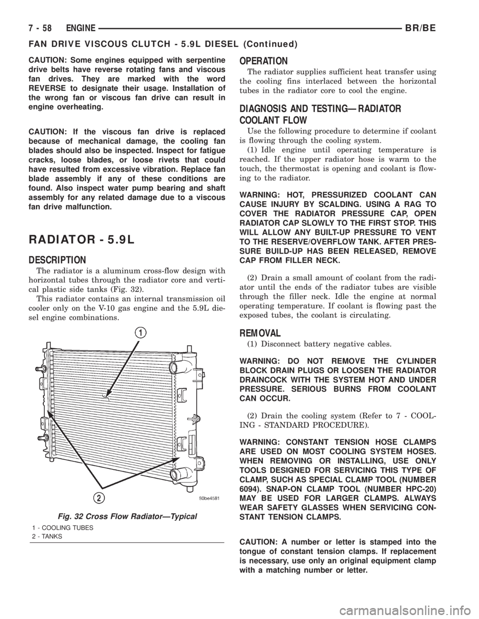
cal plastic side tanks (Fig. 32).
This radiator contains an internal transmission oil
cooler only on the V-10 gas engine and the 5.9L die-
sel engine combinations.
OPERATION
The radiator supplies sufficient heat transfer using
the cooling fins interlaced between the horizontal
tubes in the radiator core to cool the engine.
DIAGNOSIS AND TESTINGÐRADIATOR
COOLANT FLOW
Use the following procedure to determine if coolant
is flowing through the cooling system.
(1) Idle engine until operating temperature is
reached. If the upper radiator hose is warm to the
touch, the thermostat is opening and coolant is flow-
ing to the radiator.
WARNING: HOT, PRESSURIZED COOLANT CAN
CAUSE INJURY BY SCALDING. USING A RAG TO
COVER THE RADIATOR PRESSURE CAP, OPEN
RADIATOR CAP SLOWLY TO THE FIRST STOP. THIS
WILL ALLOW ANY BUILT-UP PRESSURE TO VENT
TO THE RESERVE/OVERFLOW TANK. AFTER PRES-
SURE BUILD-UP HAS BEEN RELEASED, REMOVE
CAP FROM FILLER NECK.
(2) Drain a small amount of coolant from the radi-
ator until the ends of the radiator tubes are visible
through the filler neck. Idle the engine at normal
operating temperature. If coolant is flowing past the
exposed tubes, the coolant is circulating.
REMOVAL
(1) Disconnect battery negative cables.
WARNING: DO NOT REMOVE THE CYLINDER
BLOCK DRAIN PLUGS OR LOOSEN THE RADIATOR
DRAINCOCK WITH THE SYSTEM HOT AND UNDER
PRESSURE. SERIOUS BURNS FROM COOLANT
CAN OCCUR.
(2) Drain the cooling system (Refer to 7 - COOL-
ING - STANDARD PROCEDURE).
WARNING: CONSTANT TENSION HOSE CLAMPS
ARE USED ON MOST COOLING SYSTEM HOSES.
WHEN REMOVING OR INSTALLING, USE ONLY
TOOLS DESIGNED FOR SERVICING THIS TYPE OF
CLAMP, SUCH AS SPECIAL CLAMP TOOL (NUMBER
6094). SNAP-ON CLAMP TOOL (NUMBER HPC-20)
MAY BE USED FOR LARGER CLAMPS. ALWAYS
WEAR SAFETY GLASSES WHEN SERVICING CON-
STANT TENSION CLAMPS.
CAUTION: A number or letter is stamped into the
tongue of constant tension clamps. If replacement
is necessary, use only an original equipment clamp
with a matching number or letter.
Fig. 32 Cross Flow RadiatorÐTypical
1 - COOLING TUBES
2 - TANKS
7 - 58 ENGINEBR/BE
FAN DRIVE VISCOUS CLUTCH - 5.9L DIESEL (Continued)
Page 309 of 2255
INSPECTION
Inspect the radiator side tanks for cracks, broken
or missing fittings also inspect the joint where the
tanks seam up to the radiator core for signs of leak-
age and/or deteriorating seals.
Inspect radiator core for corroded, bent or missing
cooling fins. Inspect the core for bent or damaged
cooling tubes.
INSTALLATION
(1) Position fan shroud over the fan blades rear-
ward towards engine.
(2) Install rubber insulators to alignment dowels
at lower part of radiator.
(3) Lower the radiator into position while guiding
the two alignment dowels into lower radiator sup-
port. Different alignment holes are provided in the
lower radiator support for each engine application.
(4) Install two upper radiator mounting bolts.
Tighten bolts to 11 N´m (95 in. lbs.) torque.
(5) Position the rubber shields to the sides of radi-
ator. Install the plastic clips retaining the rubber
shields to the sides of radiator.
(6) Connect both radiator hoses and install hose
clamps.
(7) Install windshield washer reservoir tank.
(8) Position fan shroud to flanges on sides of radi-
ator. Install fan shroud mounting bolts (Fig. 34).
Tighten bolts to 6 N´m (50 in. lbs.) torque.
(9) Install coolant reserve/overflow tank hose to
radiator filler neck nipple.
(10) Install coolant reserve/overflow tank to fan
shroud (fits into T-slots on shroud).
(11) Install battery negative cables.
(12) Position heater controls tofull heatposition.
(13) Fill cooling system with coolant (Refer to 7 -
COOLING - STANDARD PROCEDURE).
(14) Operate engine until it reaches normal tem-
perature. Check cooling system fluid levels.
RADIATOR - 8.0L
DESCRIPTION
The radiator is a aluminum cross-flow design with
horizontal tubes through the radiator core and verti-
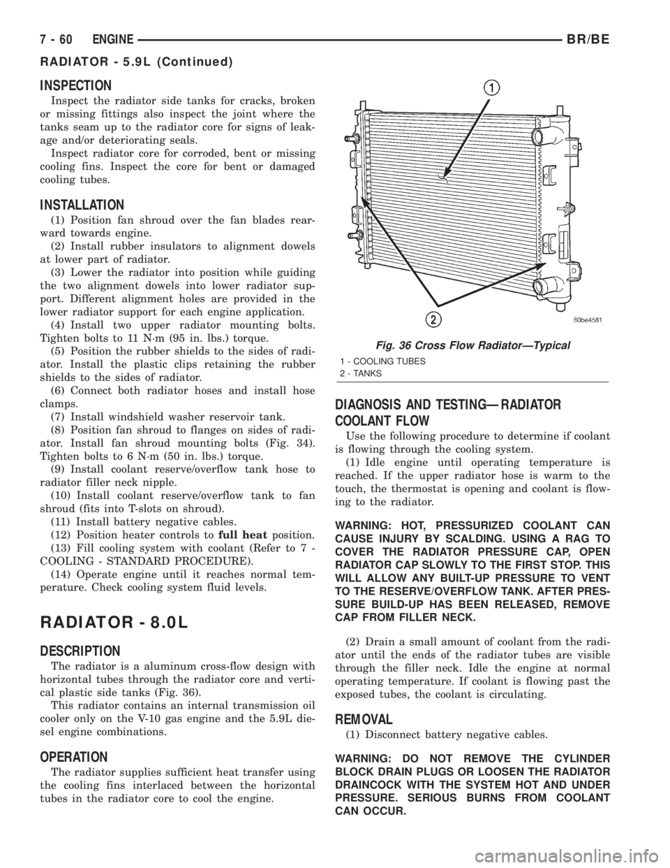
cal plastic side tanks (Fig. 36).
This radiator contains an internal transmission oil
cooler only on the V-10 gas engine and the 5.9L die-
sel engine combinations.
OPERATION
The radiator supplies sufficient heat transfer using
the cooling fins interlaced between the horizontal
tubes in the radiator core to cool the engine.
DIAGNOSIS AND TESTINGÐRADIATOR
COOLANT FLOW
Use the following procedure to determine if coolant
is flowing through the cooling system.
(1) Idle engine until operating temperature is
reached. If the upper radiator hose is warm to the
touch, the thermostat is opening and coolant is flow-
ing to the radiator.
WARNING: HOT, PRESSURIZED COOLANT CAN
CAUSE INJURY BY SCALDING. USING A RAG TO
COVER THE RADIATOR PRESSURE CAP, OPEN
RADIATOR CAP SLOWLY TO THE FIRST STOP. THIS
WILL ALLOW ANY BUILT-UP PRESSURE TO VENT
TO THE RESERVE/OVERFLOW TANK. AFTER PRES-
SURE BUILD-UP HAS BEEN RELEASED, REMOVE
CAP FROM FILLER NECK.
(2) Drain a small amount of coolant from the radi-
ator until the ends of the radiator tubes are visible
through the filler neck. Idle the engine at normal
operating temperature. If coolant is flowing past the
exposed tubes, the coolant is circulating.
REMOVAL
(1) Disconnect battery negative cables.
WARNING: DO NOT REMOVE THE CYLINDER
BLOCK DRAIN PLUGS OR LOOSEN THE RADIATOR
DRAINCOCK WITH THE SYSTEM HOT AND UNDER
PRESSURE. SERIOUS BURNS FROM COOLANT
CAN OCCUR.
Fig. 36 Cross Flow RadiatorÐTypical
1 - COOLING TUBES
2 - TANKS
7 - 60 ENGINEBR/BE
RADIATOR - 5.9L (Continued)