wheel alignment DODGE RAM 2002 Service Repair Manual
[x] Cancel search | Manufacturer: DODGE, Model Year: 2002, Model line: RAM, Model: DODGE RAM 2002Pages: 2255, PDF Size: 62.07 MB
Page 26 of 2255
SUSPENSION
TABLE OF CONTENTS
page page
WHEEL ALIGNMENT......................1
FRONT - 2WD............................7FRONT - 4WD...........................14
REAR.................................25
WHEEL ALIGNMENT
TABLE OF CONTENTS
page page
WHEEL ALIGNMENT
DESCRIPTION..........................1
OPERATION............................2
DIAGNOSIS AND TESTING - PRE-ALIGNMENT . 2
STANDARD PROCEDURE
STANDARD PROCEDURES - ALIGNMENT
I.F.S. ................................3STANDARD PROCEDURE - CASTER
CORRECTION MEASUREMENT...........3
STANDARD PROCEDURE - ALIGNMENT
LINK/COIL SUSPENSION.................5
SPECIFICATIONS
ALIGNMENT..........................6
WHEEL ALIGNMENT
DESCRIPTION
Wheel alignment is the positioning of the wheels in
relation to the vehicle. This is accomplished through
suspension and steering linkage adjustments. An
alignment is essential for efficient steering, good
directional stability and to minimize tire wear. The
most important measurements of an alignment are
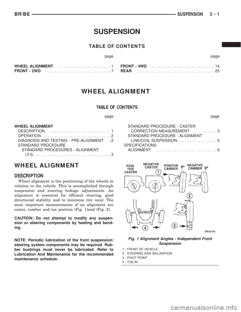
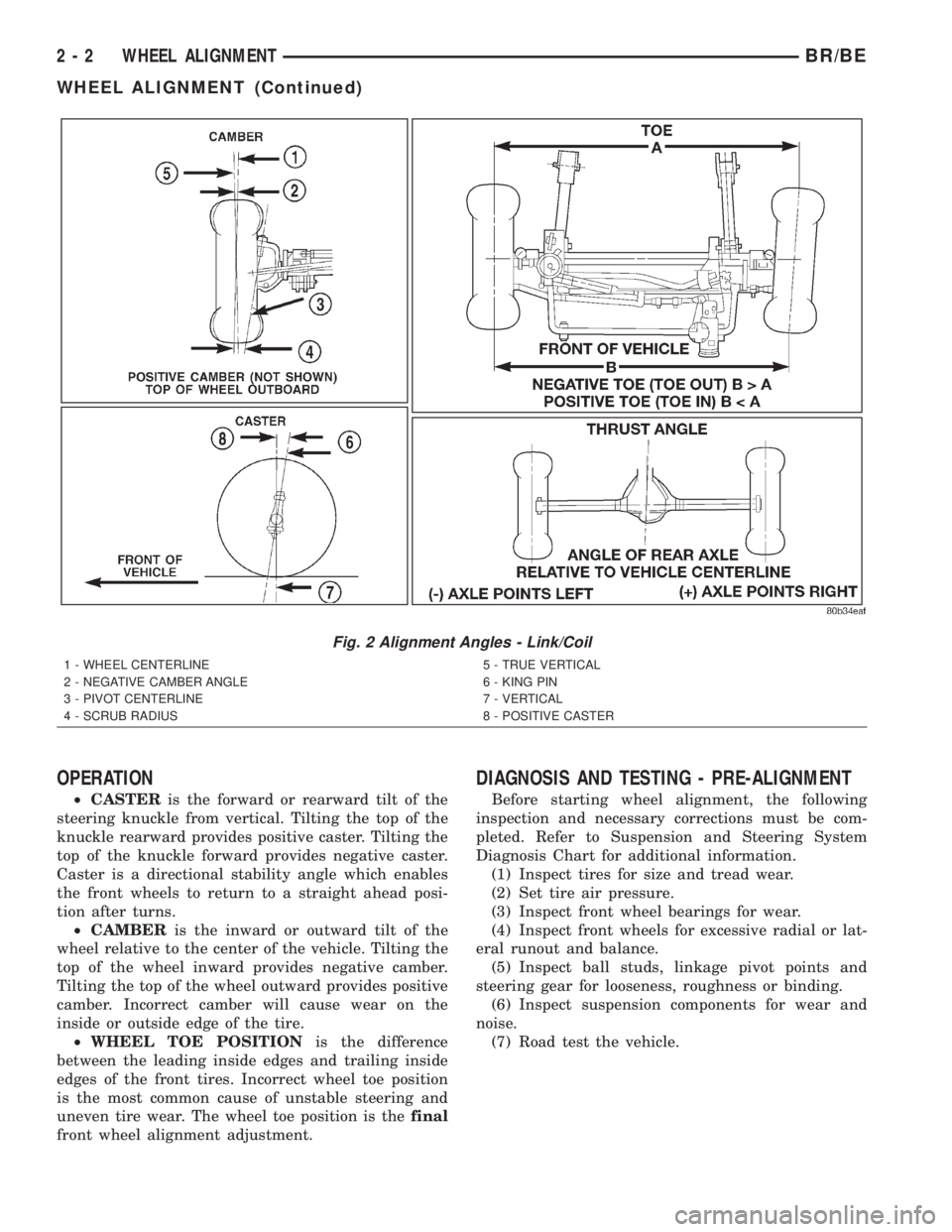
caster, camber and toe position (Fig. 1)and (Fig. 2).
CAUTION: Do not attempt to modify any suspen-
sion or steering components by heating and bend-
ing.
NOTE: Periodic lubrication of the front suspension/
steering system components may be required. Rub-
ber bushings must never be lubricated. Refer to
Lubrication And Maintenance for the recommended
maintenance schedule.
Fig. 1 Alignment Angles - Independent Front
Suspension
1 - FRONT OF VEHICLE
2 - STEERING AXIS INCLINATION
3 - PIVOT POINT
4 - TOE-IN
BR/BESUSPENSION 2 - 1
Page 27 of 2255
OPERATION
²CASTERis the forward or rearward tilt of the
steering knuckle from vertical. Tilting the top of the
knuckle rearward provides positive caster. Tilting the
top of the knuckle forward provides negative caster.
Caster is a directional stability angle which enables
the front wheels to return to a straight ahead posi-
tion after turns.
²CAMBERis the inward or outward tilt of the
wheel relative to the center of the vehicle. Tilting the
top of the wheel inward provides negative camber.
Tilting the top of the wheel outward provides positive
camber. Incorrect camber will cause wear on the
inside or outside edge of the tire.
²WHEEL TOE POSITIONis the difference
between the leading inside edges and trailing inside
edges of the front tires. Incorrect wheel toe position
is the most common cause of unstable steering and
uneven tire wear. The wheel toe position is thefinal
front wheel alignment adjustment.
DIAGNOSIS AND TESTING - PRE-ALIGNMENT
Before starting wheel alignment, the following
inspection and necessary corrections must be com-
pleted. Refer to Suspension and Steering System
Diagnosis Chart for additional information.
(1) Inspect tires for size and tread wear.
(2) Set tire air pressure.
(3) Inspect front wheel bearings for wear.
(4) Inspect front wheels for excessive radial or lat-
eral runout and balance.
(5) Inspect ball studs, linkage pivot points and
steering gear for looseness, roughness or binding.
(6) Inspect suspension components for wear and
noise.
(7) Road test the vehicle.
Fig. 2 Alignment Angles - Link/Coil
1 - WHEEL CENTERLINE
2 - NEGATIVE CAMBER ANGLE
3 - PIVOT CENTERLINE
4 - SCRUB RADIUS5 - TRUE VERTICAL
6 - KING PIN
7 - VERTICAL
8 - POSITIVE CASTER
2 - 2 WHEEL ALIGNMENTBR/BE
WHEEL ALIGNMENT (Continued)
Page 28 of 2255
STANDARD PROCEDURE
STANDARD PROCEDURES - ALIGNMENT I.F.S.
Before each alignment reading the vehicle should
be jounced (rear first, then front). Grasp each
bumper at the center and jounce the vehicle up and
down several times. Always release the bumper in
the down position.Set the front end alignment to
specifications while the vehicle is in its NOR-
MALLY LOADED CONDITION.
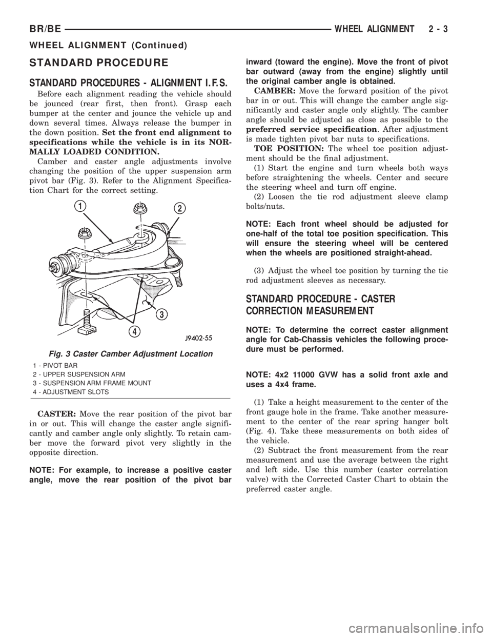
Camber and caster angle adjustments involve
changing the position of the upper suspension arm
pivot bar (Fig. 3). Refer to the Alignment Specifica-
tion Chart for the correct setting.
CASTER:Move the rear position of the pivot bar
in or out. This will change the caster angle signifi-
cantly and camber angle only slightly. To retain cam-
ber move the forward pivot very slightly in the
opposite direction.
NOTE: For example, to increase a positive caster
angle, move the rear position of the pivot barinward (toward the engine). Move the front of pivot
bar outward (away from the engine) slightly until
the original camber angle is obtained.
CAMBER:Move the forward position of the pivot
bar in or out. This will change the camber angle sig-
nificantly and caster angle only slightly. The camber
angle should be adjusted as close as possible to the
preferred service specification. After adjustment
is made tighten pivot bar nuts to specifications.
TOE POSITION:The wheel toe position adjust-
ment should be the final adjustment.
(1) Start the engine and turn wheels both ways
before straightening the wheels. Center and secure
the steering wheel and turn off engine.
(2) Loosen the tie rod adjustment sleeve clamp
bolts/nuts.
NOTE: Each front wheel should be adjusted for
one-half of the total toe position specification. This
will ensure the steering wheel will be centered
when the wheels are positioned straight-ahead.
(3) Adjust the wheel toe position by turning the tie
rod adjustment sleeves as necessary.
STANDARD PROCEDURE - CASTER
CORRECTION MEASUREMENT
NOTE: To determine the correct caster alignment
angle for Cab-Chassis vehicles the following proce-
dure must be performed.
NOTE: 4x2 11000 GVW has a solid front axle and
uses a 4x4 frame.
(1) Take a height measurement to the center of the
front gauge hole in the frame. Take another measure-
ment to the center of the rear spring hanger bolt
(Fig. 4). Take these measurements on both sides of
the vehicle.
(2) Subtract the front measurement from the rear
measurement and use the average between the right
and left side. Use this number (caster correlation
valve) with the Corrected Caster Chart to obtain the
preferred caster angle.
Fig. 3 Caster Camber Adjustment Location
1 - PIVOT BAR
2 - UPPER SUSPENSION ARM
3 - SUSPENSION ARM FRAME MOUNT
4 - ADJUSTMENT SLOTS
BR/BEWHEEL ALIGNMENT 2 - 3
WHEEL ALIGNMENT (Continued)
Page 29 of 2255
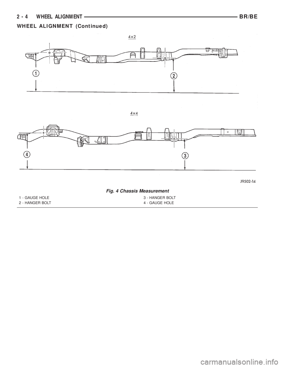
Fig. 4 Chassis Measurement
1 - GAUGE HOLE
2 - HANGER BOLT3 - HANGER BOLT
4 - GAUGE HOLE
2 - 4 WHEEL ALIGNMENTBR/BE
WHEEL ALIGNMENT (Continued)
Page 30 of 2255
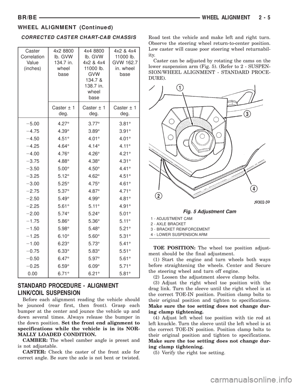
CORRECTED CASTER CHART-CAB CHASSIS
Caster
Correlation
Value
(inches)4x2 8800
lb. GVW
134.7 in.
wheel
base4x4 8800
lb. GVW
4x2 & 4x4
11000 lb.
GVW
134.7 &
138.7 in.
wheel
base4x2 & 4x4
11000 lb.
GVW 162.7
in. wheel
base
Caster 1
deg.Caster 1
deg.Caster 1
deg.
25.00 4.27É 3.77É 3.81É
24.75 4.39É 3.89É 3.91É
24.50 4.51É 4.01É 4.01É
24.25 4.64É 4.14É 4.11É
24.00 4.76É 4.26É 4.21É
23.75 4.88É 4.38É 4.31É
23.50 5.00É 4.50É 4.41É
23.25 5.12É 4.62É 4.51É
23.00 5.25É 4.75É 4.61É
22.75 5.37É 4.87É 4.71É
22.50 5.49É 4.99É 4.81É
22.25 5.61É 5.11É 4.91É
22.00 5.74É 5.24É 5.01É
21.75 5.86É 5.36É 5.11É
21.50 5.98É 5.48É 5.21É
21.25 6.10É 5.60É 5.31É
21.00 6.23É 5.73É 5.41É
20.75 6.33É 5.83É 5.51É
20.50 6.47É 5.97É 5.61É
20.25 6.59É 6.09É 5.71É
0.00 6.71É 6.21É 5.81É
STANDARD PROCEDURE - ALIGNMENT
LINK/COIL SUSPENSION
Before each alignment reading the vehicle should
be jounced (rear first, then front). Grasp each
bumper at the center and jounce the vehicle up and
down several times. Always release the bumper in
the down position.Set the front end alignment to
specifications while the vehicle is in its NOR-
MALLY LOADED CONDITION.
CAMBER:The wheel camber angle is preset and
is not adjustable.
CASTER:Check the caster of the front axle for
correct angle. Be sure the axle is not bent or twisted.Road test the vehicle and make left and right turn.
Observe the steering wheel return-to-center position.
Low caster will cause poor steering wheel returnabil-
ity.
Caster can be adjusted by rotating the cams on the
lower suspension arm (Fig. 5). (Refer to 2 - SUSPEN-
SION/WHEEL ALIGNMENT - STANDARD PROCE-
DURE).
TOE POSITION:The wheel toe position adjust-
ment should be the final adjustment.
(1) Start the engine and turn wheels both ways
before straightening the wheels. Center and Secure
the steering wheel and turn off engine.
(2) Loosen the adjustment sleeve clamp bolts.
(3) Adjust the right wheel toe position with the
drag link. Turn the sleeve until the right wheel is at
the correct TOE-IN position. Position clamp bolts to
their original position and tighten to specifications.
Make sure the toe setting does not change dur-
ing clamp tightening.
(4) Adjust left wheel toe position with tie rod at
left knuckle. Turn the sleeve until the left wheel is at
the correct TOE-IN position. Position clamp bolts to
their original position and tighten to specifications.
Make sure the toe setting does not change dur-
ing clamp tightening.
(5) Verify the right toe setting.
Fig. 5 Adjustment Cam
1 - ADJUSTMENT CAM
2 - AXLE BRACKET
3 - BRACKET REINFORCEMENT
4 - LOWER SUSPENSION ARM
BR/BEWHEEL ALIGNMENT 2 - 5
WHEEL ALIGNMENT (Continued)
Page 31 of 2255
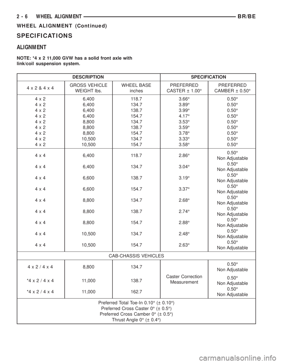
SPECIFICATIONS
ALIGNMENT
NOTE: *4x211,000 GVW has a solid front axle with
link/coil suspension system.
DESCRIPTION SPECIFICATION
4x2&4x4GROSS VEHICLE
WEIGHT lbs.WHEEL BASE
inchesPREFERRED
CASTER 1.00ÉPREFERRED
CAMBER 0.50É
4 x 2 6,400 118.7 3.66É 0.50É
4 x 2 6,400 134.7 3.89É 0.50É
4 x 2 6,400 138.7 3.99É 0.50É
4 x 2 6,400 154.7 4.17É 0.50É
4 x 2 8,800 134.7 3.53É 0.50É
4 x 2 8,800 138.7 3.59É 0.50É
4 x 2 8,800 154.7 3.78É 0.50É
4 x 2 10,500 134.7 3.33É 0.50É
4 x 2 10,500 154.7 3.58É 0.50É
4 x 4 6,400 118.7 2.86É0.50É
Non Adjustable
4 x 4 6,400 134.7 3.04É0.50É
Non Adjustable
4 x 4 6,600 138.7 3.19É0.50É
Non Adjustable
4 x 4 6,600 154.7 3.37É0.50É
Non Adjustable
4 x 4 8,800 134.7 2.68É0.50É
Non Adjustable
4 x 4 8,800 138.7 2.74É0.50É
Non Adjustable
4 x 4 8,800 154.7 2.88É0.50É
Non Adjustable
4 x 4 10,500 134.7 2.48É0.50É
Non Adjustable
4 x 4 10,500 154.7 2.63É0.50É
Non Adjustable
CAB-CHASSIS VEHICLES
4x2/4x48,800 134.7
Caster Correction
Measurement0.50É
Non Adjustable
*4x2/4x4 11,000 138.70.50É
Non Adjustable
*4x2/4x4 11,000 162.70.50É
Non Adjustable
Preferred Total Toe-In 0.10É ( 0.10É)
Preferred Cross Caster 0É ( 0.5É)
Preferred Cross Camber 0É ( 0.5É)
Thrust Angle 0É ( 0.4É)
2 - 6 WHEEL ALIGNMENTBR/BE
WHEEL ALIGNMENT (Continued)
Page 38 of 2255
UPPER CONTROL ARM
REMOVAL
(1) Raise and support vehicle.
(2) Remove tire and wheel assembly.
(3) Support lower suspension arm at outboard end
with jack stand.
(4) Remove upper ball joint cotter pin and nut.
(5) Separate ball joint from knuckle with remover
MB-990635.
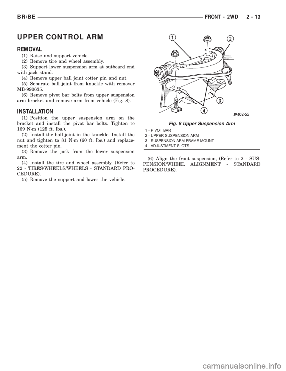
(6) Remove pivot bar bolts from upper suspension
arm bracket and remove arm from vehicle (Fig. 8).
INSTALLATION
(1) Position the upper suspension arm on the
bracket and install the pivot bar bolts. Tighten to
169 N´m (125 ft. lbs.).
(2) Install the ball joint in the knuckle. Install the
nut and tighten to 81 N´m (60 ft. lbs.) and replace-
ment the cotter pin.
(3) Remove the jack from the lower suspension
arm.
(4) Install the tire and wheel assembly, (Refer to
22 - TIRES/WHEELS/WHEELS - STANDARD PRO-
CEDURE).
(5) Remove the support and lower the vehicle.(6) Align the front suspension, (Refer to 2 - SUS-
PENSION/WHEEL ALIGNMENT - STANDARD
PROCEDURE).
Fig. 8 Upper Suspension Arm
1 - PIVOT BAR
2 - UPPER SUSPENSION ARM
3 - SUSPENSION ARM FRAME MOUNT
4 - ADJUSTMENT SLOTS
BR/BEFRONT - 2WD 2 - 13
Page 58 of 2255
(15) If the vibration remains unacceptable, apply
the same steps to the front end of the propeller shaft.
(16) Install the wheel and tires. Lower the vehicle.
RUNOUT
(1) Remove dirt, rust, paint and undercoating from
the propeller shaft surface where the dial indicator
will contact the shaft.
(2) The dial indicator must be installed perpendic-
ular to the shaft surface.
(3) Measure runout at the center and ends of the
shaft sufficiently far away from weld areas to ensure
that the effects of the weld process will not enter into
the measurements.
(4) Refer to Runout Specifications chart.
(5) If propeller shaft runout is out of specification,
remove the propeller shaft, index the shaft 180É and
re-install the propeller shaft. Measure shaft runout
again.
(6) If propeller shaft runout is now within specifi-
cations, mark the shaft and yokes for proper orienta-
tion.
(7) If the propeller shaft runout is not within spec-
ifications, verify that the runout of the transmission/
transfer case and axle are within specifications.
Correct as necessary and re-measure propeller shaft
runout.
(8) Replace the propeller shaft if the runout still
exceeds the limits.
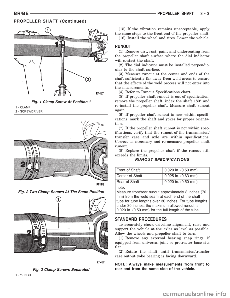
RUNOUT SPECIFICATIONS
Front of Shaft 0.020 in. (0.50 mm)
Center of Shaft 0.025 in. (0.63 mm)
Rear of Shaft 0.020 in. (0.50 mm)
note:
Measure front/rear runout approximately 3 inches (76
mm) from the weld seam at each end of the shaft
tube for tube lengths over 30 inches. For tube lengths
under 30 inches, the maximum allowed runout is
0.020 in. (0.50 mm) for the full length of the tube.
STANDARD PROCEDURES
To accurately check driveline alignment, raise and
support the vehicle at the axles as level as possible.
Allow the wheels and propeller shaft to turn.
(1) Remove any external bearing snap rings, if
equipped from universal joint so protractor base sits
flat.
(2) Rotate the shaft until transmission/transfer
case output yoke bearing is facing downward.
NOTE: Always make measurements from front to
rear and from the same side of the vehicle.
Fig. 1 Clamp Screw At Position 1
1 - CLAMP
2 - SCREWDRIVER
Fig. 2 Two Clamp Screws At The Same Position
Fig. 3 Clamp Screws Separated
1 - ó INCH
BR/BEPROPELLER SHAFT 3 - 3
PROPELLER SHAFT (Continued)
Page 71 of 2255
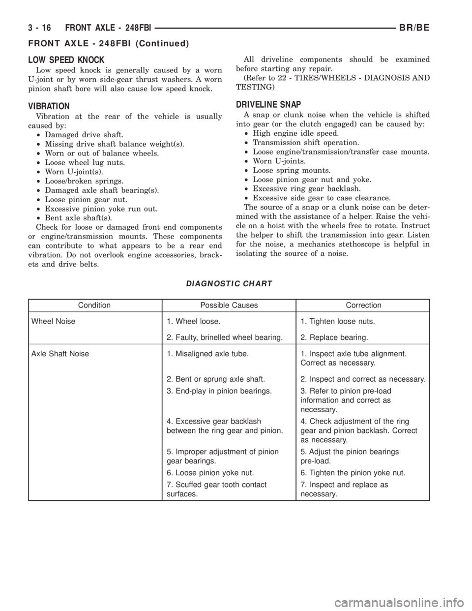
LOW SPEED KNOCK
Low speed knock is generally caused by a worn
U-joint or by worn side-gear thrust washers. A worn
pinion shaft bore will also cause low speed knock.
VIBRATION
Vibration at the rear of the vehicle is usually
caused by:
²Damaged drive shaft.
²Missing drive shaft balance weight(s).
²Worn or out of balance wheels.
²Loose wheel lug nuts.
²Worn U-joint(s).
²Loose/broken springs.
²Damaged axle shaft bearing(s).
²Loose pinion gear nut.
²Excessive pinion yoke run out.
²Bent axle shaft(s).
Check for loose or damaged front end components
or engine/transmission mounts. These components
can contribute to what appears to be a rear end
vibration. Do not overlook engine accessories, brack-
ets and drive belts.All driveline components should be examined
before starting any repair.
(Refer to 22 - TIRES/WHEELS - DIAGNOSIS AND
TESTING)
DRIVELINE SNAP
A snap or clunk noise when the vehicle is shifted
into gear (or the clutch engaged) can be caused by:
²High engine idle speed.
²Transmission shift operation.
²Loose engine/transmission/transfer case mounts.
²Worn U-joints.
²Loose spring mounts.
²Loose pinion gear nut and yoke.
²Excessive ring gear backlash.
²Excessive side gear to case clearance.
The source of a snap or a clunk noise can be deter-
mined with the assistance of a helper. Raise the vehi-
cle on a hoist with the wheels free to rotate. Instruct
the helper to shift the transmission into gear. Listen
for the noise, a mechanics stethoscope is helpful in
isolating the source of a noise.
DIAGNOSTIC CHART
Condition Possible Causes Correction
Wheel Noise 1. Wheel loose. 1. Tighten loose nuts.
2. Faulty, brinelled wheel bearing. 2. Replace bearing.
Axle Shaft Noise 1. Misaligned axle tube. 1. Inspect axle tube alignment.
Correct as necessary.
2. Bent or sprung axle shaft. 2. Inspect and correct as necessary.
3. End-play in pinion bearings. 3. Refer to pinion pre-load
information and correct as
necessary.
4. Excessive gear backlash
between the ring gear and pinion.4. Check adjustment of the ring
gear and pinion backlash. Correct
as necessary.
5. Improper adjustment of pinion
gear bearings.5. Adjust the pinion bearings
pre-load.
6. Loose pinion yoke nut. 6. Tighten the pinion yoke nut.
7. Scuffed gear tooth contact
surfaces.7. Inspect and replace as
necessary.
3 - 16 FRONT AXLE - 248FBIBR/BE
FRONT AXLE - 248FBI (Continued)
Page 72 of 2255
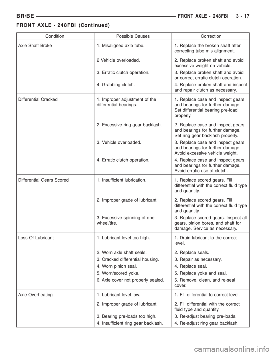
Condition Possible Causes Correction
Axle Shaft Broke 1. Misaligned axle tube. 1. Replace the broken shaft after
correcting tube mis-alignment.
2 Vehicle overloaded. 2. Replace broken shaft and avoid
excessive weight on vehicle.
3. Erratic clutch operation. 3. Replace broken shaft and avoid
or correct erratic clutch operation.
4. Grabbing clutch. 4. Replace broken shaft and inspect
and repair clutch as necessary.
Differential Cracked 1. Improper adjustment of the
differential bearings.1. Replace case and inspect gears
and bearings for further damage.
Set differential bearing pre-load
properly.
2. Excessive ring gear backlash. 2. Replace case and inspect gears
and bearings for further damage.
Set ring gear backlash properly.
3. Vehicle overloaded. 3. Replace case and inspect gears
and bearings for further damage.
Avoid excessive vehicle weight.
4. Erratic clutch operation. 4. Replace case and inspect gears
and bearings for further damage.
Avoid erratic use of clutch.
Differential Gears Scored 1. Insufficient lubrication. 1. Replace scored gears. Fill
differential with the correct fluid type
and quantity.
2. Improper grade of lubricant. 2. Replace scored gears. Fill
differential with the correct fluid type
and quantity.
3. Excessive spinning of one
wheel/tire.3. Replace scored gears. Inspect all
gears, pinion bores, and shaft for
damage. Service as necessary.
Loss Of Lubricant 1. Lubricant level too high. 1. Drain lubricant to the correct
level.
2. Worn axle shaft seals. 2. Replace seals.
3. Cracked differential housing. 3. Repair as necessary.
4. Worn pinion seal. 4. Replace seal.
5. Worn/scored yoke. 5. Replace yoke and seal.
6. Axle cover not properly sealed. 6. Remove, clean, and re-seal
cover.
Axle Overheating 1. Lubricant level low. 1. Fill differential to correct level.
2. Improper grade of lubricant. 2. Fill differential with the correct
fluid type and quantity.
3. Bearing pre-loads too high. 3. Re-adjust bearing pre-loads.
4. Insufficient ring gear backlash. 4. Re-adjust ring gear backlash.
BR/BEFRONT AXLE - 248FBI 3 - 17
FRONT AXLE - 248FBI (Continued)