seat adjustment DODGE RAM 2002 Service Repair Manual
[x] Cancel search | Manufacturer: DODGE, Model Year: 2002, Model line: RAM, Model: DODGE RAM 2002Pages: 2255, PDF Size: 62.07 MB
Page 63 of 2255
CENTER BEARING
REMOVAL
(1) Remove rear propeller shaft.
(2) Remove slip joint boot clamp and separate the
two half-shafts.
(3) Use hammer and punch to tap slinger away
from shaft to provide room for bearing splitter.
(4) Position Bearing Splitter Tool 1130 between
slinger and shaft.
CAUTION: Do not damage shaft spline during
removal of center bearing.
(5)
Set shaft in press and press bearing off the shaft.
INSTALLATION
NOTE: Two types of center bearings are used and
are not interchangeable. Install the same type as
the vehicle was built with.
(1) Install new slinger on shaft and drive into posi-
tion with appropriate installer tool.
(2) Install new center bearing on shaft with Bear-
ing Installer Tool 6052. Drive on shaft with hammer
until bearing is seated.
(3) Clean shaft splines and apply a coat of multi-
purpose grease.
(4) Align master splines and slide front and rear
half-shafts together. Reposition slip yoke boot and
install new clamp.
(5) Install propeller shaft in vehicle.
ADJUSTMENTS
ADJUSTMENT - CENTER BEARING
Launch shudder is a vibration that occurs at first
acceleration from a stop. Shudder vibration usually
peaks at the engines highest torque output. Shudder is
a symptom associated with vehicles using a two-piece
propeller shaft. To decrease shudder, lower the center
bearing in 1/8 inch increments. Use shim stock or fab-
ricated plates. Plate stock must be used to maintain
compression of the rubber insulator around the bearing.
Do not use washers. Replace the original bolts with the
appropriate increased length bolts.
SINGLE CARDAN UNIVERSAL
JOINTS
DISASSEMBLY
Individual components of cardan universal joints
are not serviceable. If worn or leaking, they must be
replaced as an assembly.
(1) Remove the propeller shaft.
(2) With a soft drift, tap the outside of the bearing
cap assembly to loosen snap ring.
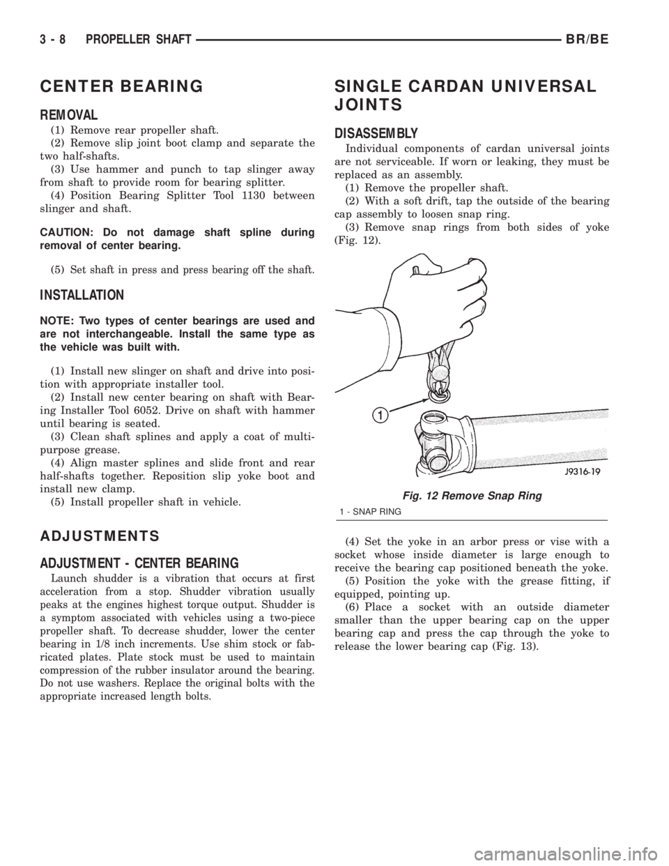
(3) Remove snap rings from both sides of yoke
(Fig. 12).
(4) Set the yoke in an arbor press or vise with a
socket whose inside diameter is large enough to
receive the bearing cap positioned beneath the yoke.
(5) Position the yoke with the grease fitting, if
equipped, pointing up.
(6) Place a socket with an outside diameter
smaller than the upper bearing cap on the upper
bearing cap and press the cap through the yoke to
release the lower bearing cap (Fig. 13).
Fig. 12 Remove Snap Ring
1 - SNAP RING
3 - 8 PROPELLER SHAFTBR/BE
Page 94 of 2255
INSTALLATION
NOTE: If replacement differential bearings or differ-
ential case are being installed, differential side
bearing shim requirements may change. Refer to
Adjustments (Differential Bearing Preload and Gear
Backlash) procedures to determine proper shim
selection.
(1) Position Spreader W-129-B with the tool dowel
pins seated in the locating holes. Install the hold
down clamps and tighten the tool turnbuckle finger-
tight.
(2) Install a Pilot Stud C-3288-B at the left side of
the differential housing and attach dial indicator to
the pilot stud. Load the indicator plunger against the
opposite side of the housing and zero the dial indica-
tor.
(3) Spread the housing enough to install the case
in the housing. Measure the distance with the dial
indicator.
CAUTION: Never spread the housing over 0.50 mm
(0.020 in). If housing is over-spread, it could be dis-
torted or damaged.
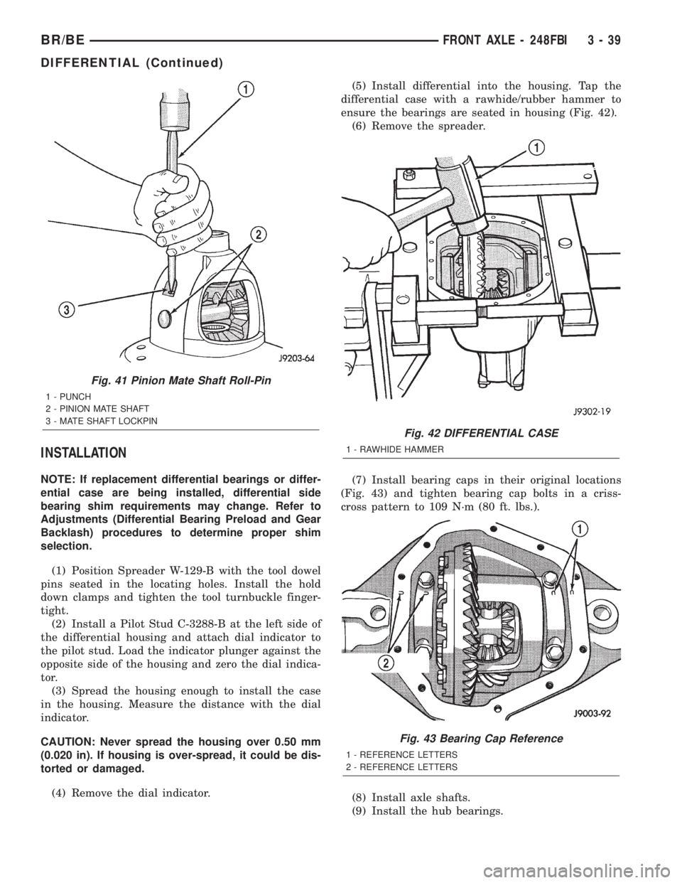
(4) Remove the dial indicator.(5) Install differential into the housing. Tap the
differential case with a rawhide/rubber hammer to
ensure the bearings are seated in housing (Fig. 42).
(6) Remove the spreader.
(7) Install bearing caps in their original locations
(Fig. 43) and tighten bearing cap bolts in a criss-
cross pattern to 109 N´m (80 ft. lbs.).
(8) Install axle shafts.
(9) Install the hub bearings.
Fig. 41 Pinion Mate Shaft Roll-Pin
1 - PUNCH
2 - PINION MATE SHAFT
3 - MATE SHAFT LOCKPIN
Fig. 42 DIFFERENTIAL CASE
1 - RAWHIDE HAMMER
Fig. 43 Bearing Cap Reference
1 - REFERENCE LETTERS
2 - REFERENCE LETTERS
BR/BEFRONT AXLE - 248FBI 3 - 39
DIFFERENTIAL (Continued)
Page 98 of 2255
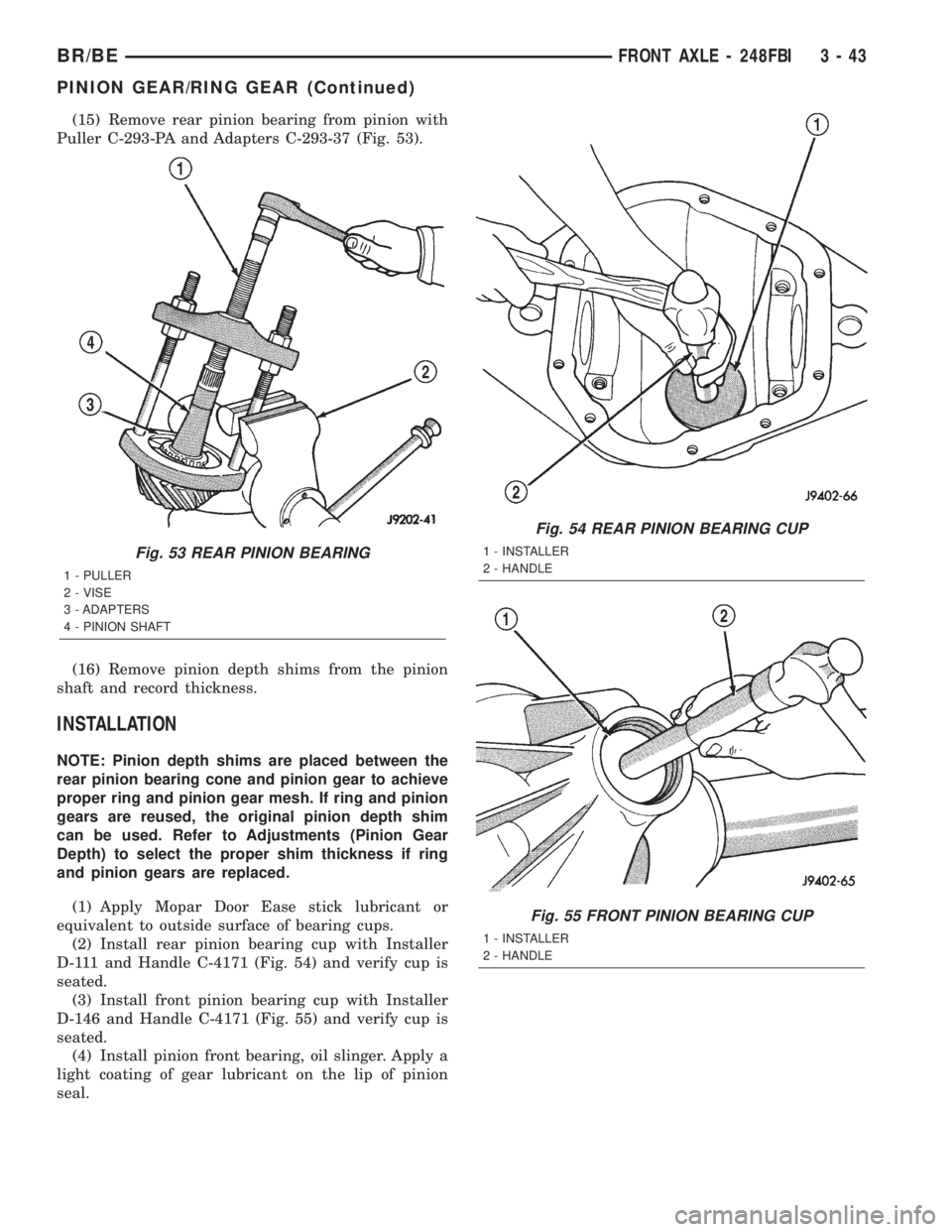
(15) Remove rear pinion bearing from pinion with
Puller C-293-PA and Adapters C-293-37 (Fig. 53).
(16) Remove pinion depth shims from the pinion
shaft and record thickness.
INSTALLATION
NOTE: Pinion depth shims are placed between the
rear pinion bearing cone and pinion gear to achieve
proper ring and pinion gear mesh. If ring and pinion
gears are reused, the original pinion depth shim
can be used. Refer to Adjustments (Pinion Gear
Depth) to select the proper shim thickness if ring
and pinion gears are replaced.
(1) Apply Mopar Door Ease stick lubricant or
equivalent to outside surface of bearing cups.
(2) Install rear pinion bearing cup with Installer
D-111 and Handle C-4171 (Fig. 54) and verify cup is
seated.
(3) Install front pinion bearing cup with Installer
D-146 and Handle C-4171 (Fig. 55) and verify cup is
seated.
(4) Install pinion front bearing, oil slinger. Apply a
light coating of gear lubricant on the lip of pinion
seal.
Fig. 53 REAR PINION BEARING
1 - PULLER
2 - VISE
3 - ADAPTERS
4 - PINION SHAFT
Fig. 54 REAR PINION BEARING CUP
1 - INSTALLER
2 - HANDLE
Fig. 55 FRONT PINION BEARING CUP
1 - INSTALLER
2 - HANDLE
BR/BEFRONT AXLE - 248FBI 3 - 43
PINION GEAR/RING GEAR (Continued)
Page 121 of 2255
(4) Remove the differential side gears and thrust
washers.
ASSEMBLY
(1) Install the differential side gears and thrust
washers.
(2) Install the pinion mate gears and thrust wash-
ers.
(3) Install the pinion gear mate shaft.
(4) Align the hole in the pinion gear mate shaft
with the hole in the differential case.
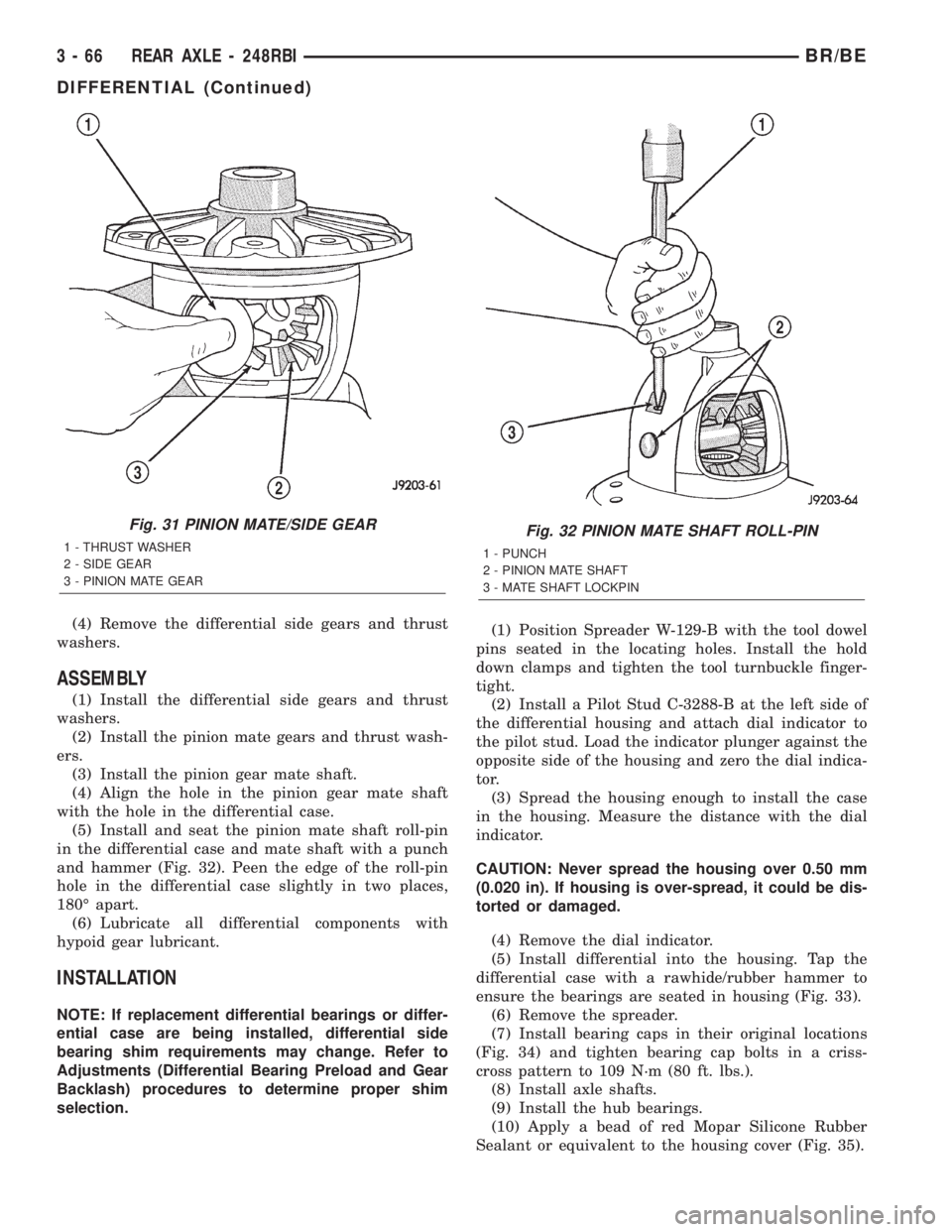
(5) Install and seat the pinion mate shaft roll-pin
in the differential case and mate shaft with a punch
and hammer (Fig. 32). Peen the edge of the roll-pin
hole in the differential case slightly in two places,
180É apart.
(6) Lubricate all differential components with
hypoid gear lubricant.
INSTALLATION
NOTE: If replacement differential bearings or differ-
ential case are being installed, differential side
bearing shim requirements may change. Refer to
Adjustments (Differential Bearing Preload and Gear
Backlash) procedures to determine proper shim
selection.(1) Position Spreader W-129-B with the tool dowel
pins seated in the locating holes. Install the hold
down clamps and tighten the tool turnbuckle finger-
tight.
(2) Install a Pilot Stud C-3288-B at the left side of
the differential housing and attach dial indicator to
the pilot stud. Load the indicator plunger against the
opposite side of the housing and zero the dial indica-
tor.
(3) Spread the housing enough to install the case
in the housing. Measure the distance with the dial
indicator.
CAUTION: Never spread the housing over 0.50 mm
(0.020 in). If housing is over-spread, it could be dis-
torted or damaged.
(4) Remove the dial indicator.
(5) Install differential into the housing. Tap the
differential case with a rawhide/rubber hammer to
ensure the bearings are seated in housing (Fig. 33).
(6) Remove the spreader.
(7) Install bearing caps in their original locations
(Fig. 34) and tighten bearing cap bolts in a criss-
cross pattern to 109 N´m (80 ft. lbs.).
(8) Install axle shafts.
(9) Install the hub bearings.
(10) Apply a bead of red Mopar Silicone Rubber
Sealant or equivalent to the housing cover (Fig. 35).
Fig. 31 PINION MATE/SIDE GEAR
1 - THRUST WASHER
2 - SIDE GEAR
3 - PINION MATE GEARFig. 32 PINION MATE SHAFT ROLL-PIN
1 - PUNCH
2 - PINION MATE SHAFT
3 - MATE SHAFT LOCKPIN
3 - 66 REAR AXLE - 248RBIBR/BE
DIFFERENTIAL (Continued)
Page 130 of 2255
INSTALLATION
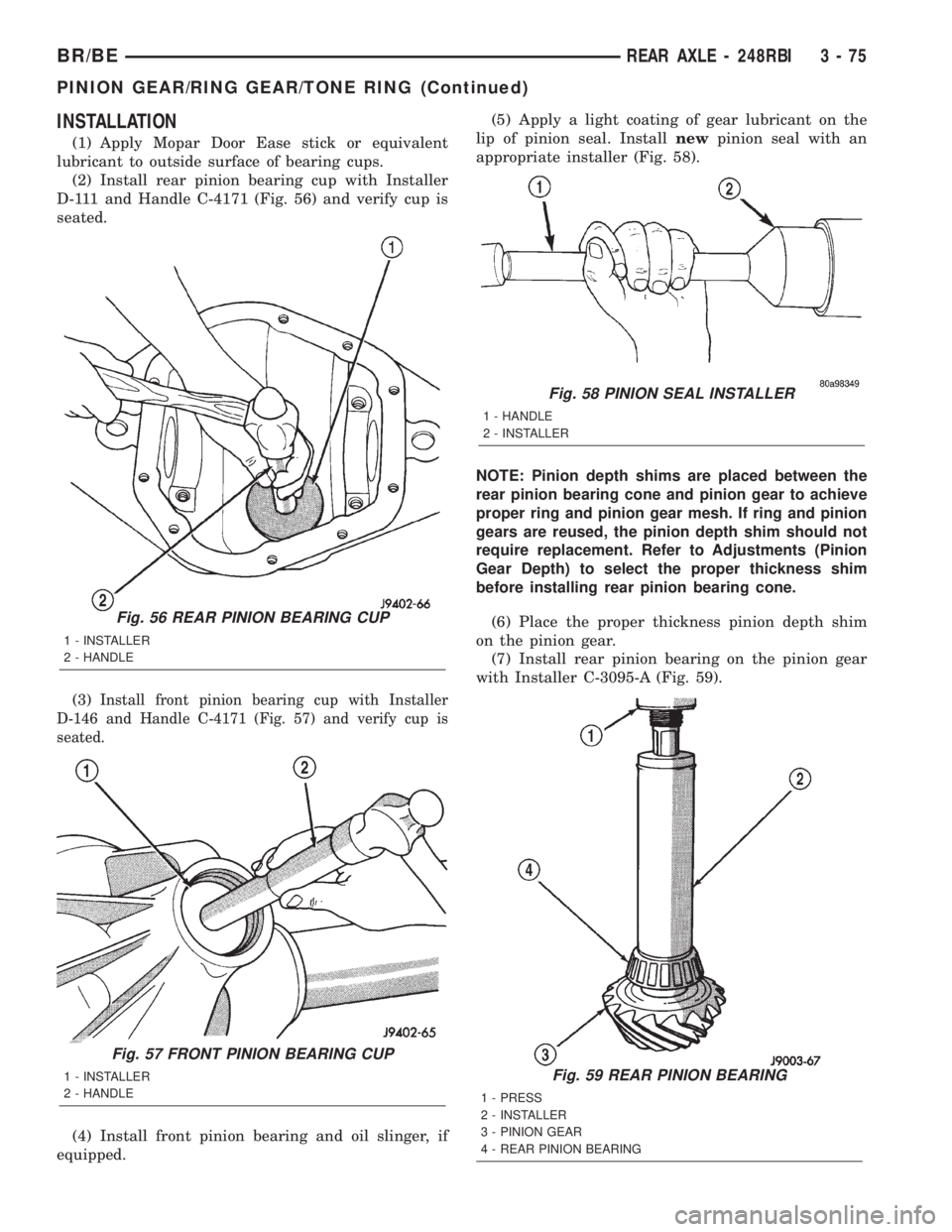
(1) Apply Mopar Door Ease stick or equivalent
lubricant to outside surface of bearing cups.
(2) Install rear pinion bearing cup with Installer
D-111 and Handle C-4171 (Fig. 56) and verify cup is
seated.
(3)
Install front pinion bearing cup with Installer
D-146 and Handle C-4171 (Fig. 57) and verify cup is
seated.
(4) Install front pinion bearing and oil slinger, if
equipped.(5) Apply a light coating of gear lubricant on the
lip of pinion seal. Installnewpinion seal with an
appropriate installer (Fig. 58).
NOTE: Pinion depth shims are placed between the
rear pinion bearing cone and pinion gear to achieve
proper ring and pinion gear mesh. If ring and pinion
gears are reused, the pinion depth shim should not
require replacement. Refer to Adjustments (Pinion
Gear Depth) to select the proper thickness shim
before installing rear pinion bearing cone.
(6) Place the proper thickness pinion depth shim
on the pinion gear.
(7) Install rear pinion bearing on the pinion gear
with Installer C-3095-A (Fig. 59).
Fig. 59 REAR PINION BEARING
1 - PRESS
2 - INSTALLER
3 - PINION GEAR
4 - REAR PINION BEARING
Fig. 56 REAR PINION BEARING CUP
1 - INSTALLER
2 - HANDLE
Fig. 57 FRONT PINION BEARING CUP
1 - INSTALLER
2 - HANDLE
Fig. 58 PINION SEAL INSTALLER
1 - HANDLE
2 - INSTALLER
BR/BEREAR AXLE - 248RBI 3 - 75
PINION GEAR/RING GEAR/TONE RING (Continued)
Page 152 of 2255
DISASSEMBLY
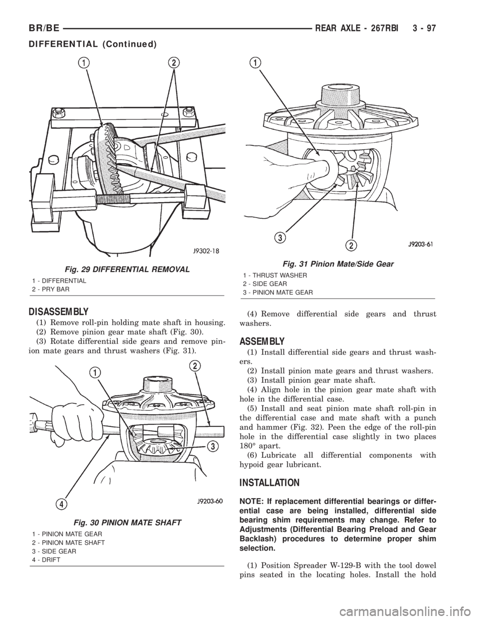
(1) Remove roll-pin holding mate shaft in housing.
(2) Remove pinion gear mate shaft (Fig. 30).
(3) Rotate differential side gears and remove pin-
ion mate gears and thrust washers (Fig. 31).(4) Remove differential side gears and thrust
washers.
ASSEMBLY
(1) Install differential side gears and thrust wash-
ers.
(2) Install pinion mate gears and thrust washers.
(3) Install pinion gear mate shaft.
(4) Align hole in the pinion gear mate shaft with
hole in the differential case.
(5) Install and seat pinion mate shaft roll-pin in
the differential case and mate shaft with a punch
and hammer (Fig. 32). Peen the edge of the roll-pin
hole in the differential case slightly in two places
180É apart.
(6) Lubricate all differential components with
hypoid gear lubricant.
INSTALLATION
NOTE: If replacement differential bearings or differ-
ential case are being installed, differential side
bearing shim requirements may change. Refer to
Adjustments (Differential Bearing Preload and Gear
Backlash) procedures to determine proper shim
selection.
(1) Position Spreader W-129-B with the tool dowel
pins seated in the locating holes. Install the hold
Fig. 29 DIFFERENTIAL REMOVAL
1 - DIFFERENTIAL
2-PRYBAR
Fig. 30 PINION MATE SHAFT
1 - PINION MATE GEAR
2 - PINION MATE SHAFT
3 - SIDE GEAR
4 - DRIFT
Fig. 31 Pinion Mate/Side Gear
1 - THRUST WASHER
2 - SIDE GEAR
3 - PINION MATE GEAR
BR/BEREAR AXLE - 267RBI 3 - 97
DIFFERENTIAL (Continued)
Page 160 of 2255
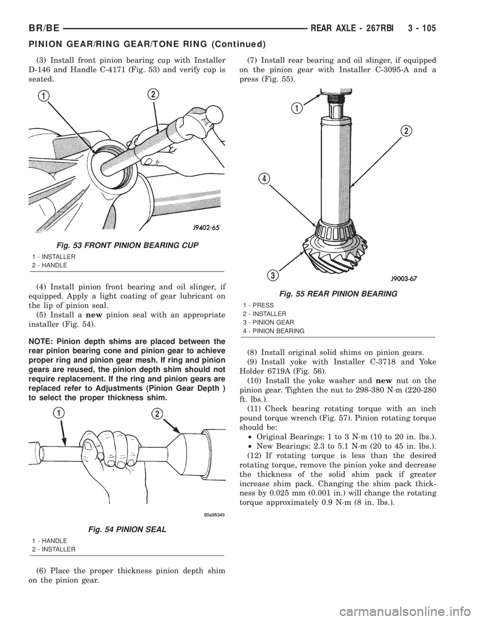
(3) Install front pinion bearing cup with Installer
D-146 and Handle C-4171 (Fig. 53) and verify cup is
seated.
(4) Install pinion front bearing and oil slinger, if
equipped. Apply a light coating of gear lubricant on
the lip of pinion seal.
(5) Install anewpinion seal with an appropriate
installer (Fig. 54).
NOTE: Pinion depth shims are placed between the
rear pinion bearing cone and pinion gear to achieve
proper ring and pinion gear mesh. If ring and pinion
gears are reused, the pinion depth shim should not
require replacement. If the ring and pinion gears are
replaced refer to Adjustments (Pinion Gear Depth )
to select the proper thickness shim.
(6) Place the proper thickness pinion depth shim
on the pinion gear.(7) Install rear bearing and oil slinger, if equipped
on the pinion gear with Installer C-3095-A and a
press (Fig. 55).
(8) Install original solid shims on pinion gears.
(9) Install yoke with Installer C-3718 and Yoke
Holder 6719A (Fig. 56).
(10) Install the yoke washer andnewnut on the
pinion gear. Tighten the nut to 298-380 N´m (220-280
ft. lbs.).
(11) Check bearing rotating torque with an inch
pound torque wrench (Fig. 57). Pinion rotating torque
should be:
²Original Bearings: 1 to 3 N´m (10 to 20 in. lbs.).
²New Bearings: 2.3 to 5.1 N´m (20 to 45 in. lbs.).
(12) If rotating torque is less than the desired
rotating torque, remove the pinion yoke and decrease
the thickness of the solid shim pack if greater
increase shim pack. Changing the shim pack thick-
ness by 0.025 mm (0.001 in.) will change the rotating
torque approximately 0.9 N´m (8 in. lbs.).
Fig. 53 FRONT PINION BEARING CUP
1 - INSTALLER
2 - HANDLE
Fig. 54 PINION SEAL
1 - HANDLE
2 - INSTALLER
Fig. 55 REAR PINION BEARING
1 - PRESS
2 - INSTALLER
3 - PINION GEAR
4 - PINION BEARING
BR/BEREAR AXLE - 267RBI 3 - 105
PINION GEAR/RING GEAR/TONE RING (Continued)
Page 181 of 2255
(14) Remove the case from housing. Tag bearing
cups to indicate their location.
DISASSEMBLY
(1) Remove roll-pin holding mate shaft in housing.
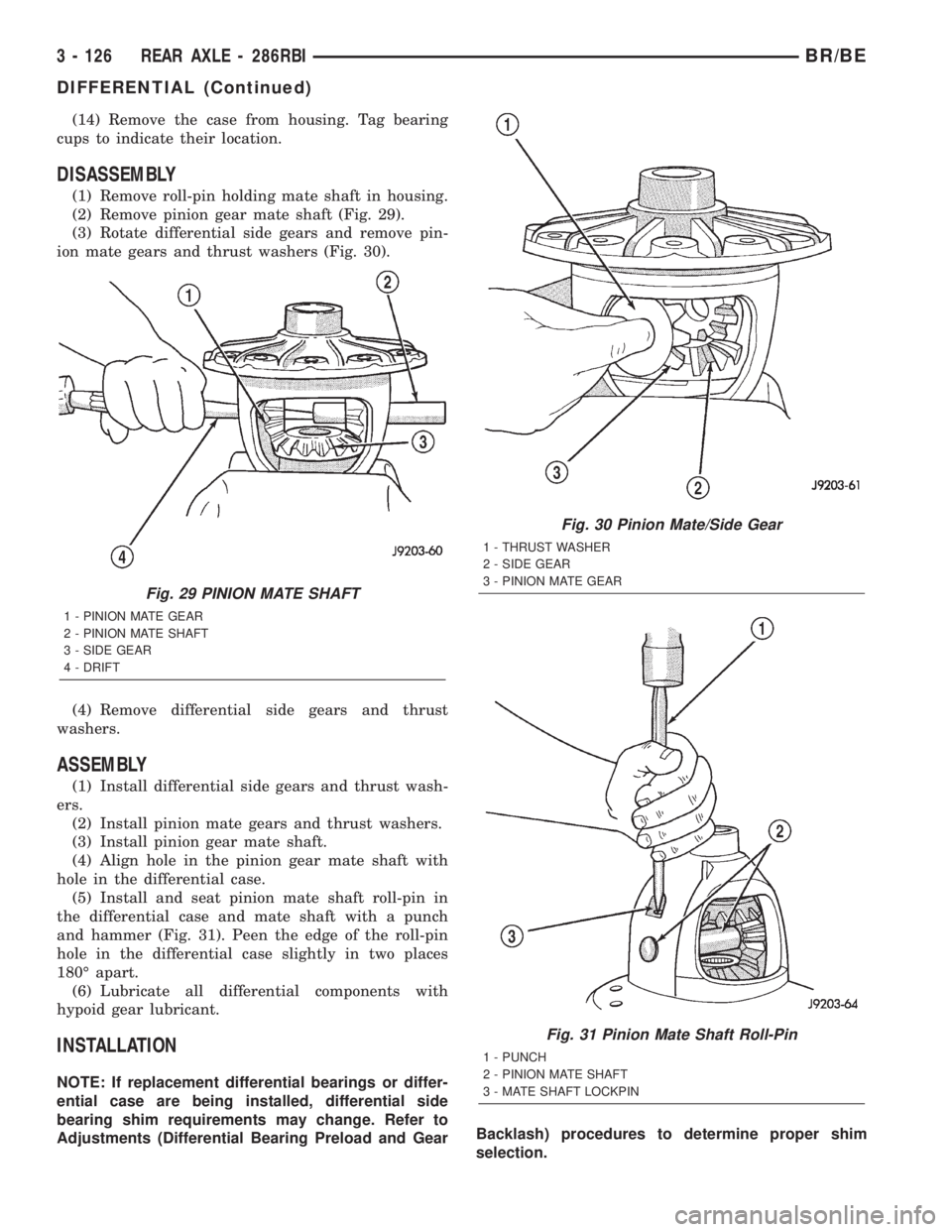
(2) Remove pinion gear mate shaft (Fig. 29).
(3) Rotate differential side gears and remove pin-
ion mate gears and thrust washers (Fig. 30).
(4) Remove differential side gears and thrust
washers.
ASSEMBLY
(1) Install differential side gears and thrust wash-
ers.
(2) Install pinion mate gears and thrust washers.
(3) Install pinion gear mate shaft.
(4) Align hole in the pinion gear mate shaft with
hole in the differential case.
(5) Install and seat pinion mate shaft roll-pin in
the differential case and mate shaft with a punch
and hammer (Fig. 31). Peen the edge of the roll-pin
hole in the differential case slightly in two places
180É apart.
(6) Lubricate all differential components with
hypoid gear lubricant.
INSTALLATION
NOTE: If replacement differential bearings or differ-
ential case are being installed, differential side
bearing shim requirements may change. Refer to
Adjustments (Differential Bearing Preload and GearBacklash) procedures to determine proper shim
selection.
Fig. 29 PINION MATE SHAFT
1 - PINION MATE GEAR
2 - PINION MATE SHAFT
3 - SIDE GEAR
4 - DRIFT
Fig. 30 Pinion Mate/Side Gear
1 - THRUST WASHER
2 - SIDE GEAR
3 - PINION MATE GEAR
Fig. 31 Pinion Mate Shaft Roll-Pin
1 - PUNCH
2 - PINION MATE SHAFT
3 - MATE SHAFT LOCKPIN
3 - 126 REAR AXLE - 286RBIBR/BE
DIFFERENTIAL (Continued)
Page 219 of 2255
(3) Remove the front cable from the cable connec-
tor.
(4) Compress cable end fitting at underbody
bracket and remove the cable from the bracket.
(5) Lower vehicle.
(6) Push ball end of cable out of pedal clevis with
small screwdriver.
(7) Compress cable end fitting at the pedal bracket
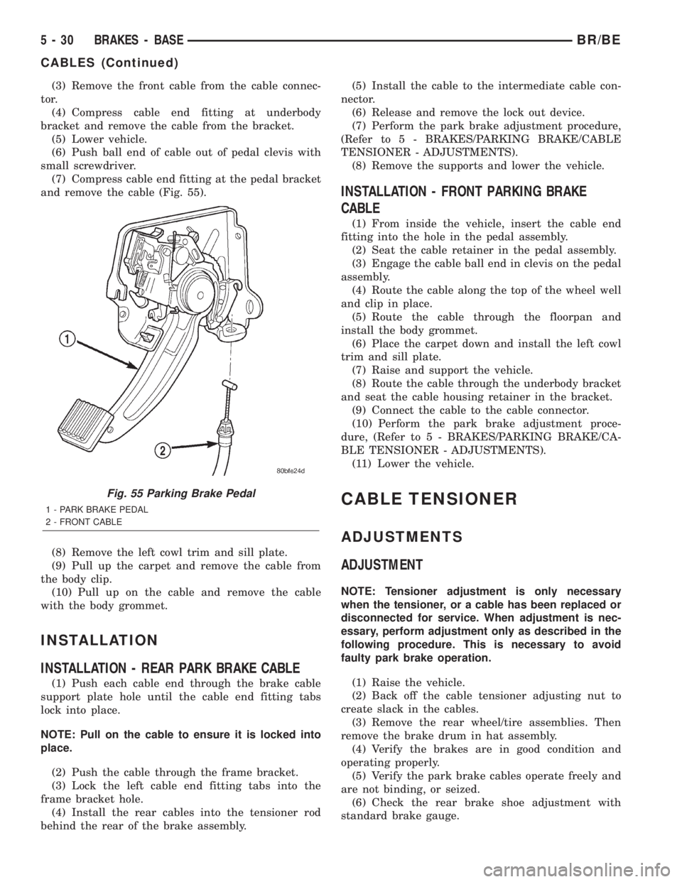
and remove the cable (Fig. 55).
(8) Remove the left cowl trim and sill plate.
(9) Pull up the carpet and remove the cable from
the body clip.
(10) Pull up on the cable and remove the cable
with the body grommet.
INSTALLATION
INSTALLATION - REAR PARK BRAKE CABLE
(1) Push each cable end through the brake cable
support plate hole until the cable end fitting tabs
lock into place.
NOTE: Pull on the cable to ensure it is locked into
place.
(2) Push the cable through the frame bracket.
(3) Lock the left cable end fitting tabs into the
frame bracket hole.
(4) Install the rear cables into the tensioner rod
behind the rear of the brake assembly.(5) Install the cable to the intermediate cable con-
nector.
(6) Release and remove the lock out device.
(7) Perform the park brake adjustment procedure,
(Refer to 5 - BRAKES/PARKING BRAKE/CABLE
TENSIONER - ADJUSTMENTS).
(8) Remove the supports and lower the vehicle.
INSTALLATION - FRONT PARKING BRAKE
CABLE
(1) From inside the vehicle, insert the cable end
fitting into the hole in the pedal assembly.
(2) Seat the cable retainer in the pedal assembly.
(3) Engage the cable ball end in clevis on the pedal
assembly.
(4) Route the cable along the top of the wheel well
and clip in place.
(5) Route the cable through the floorpan and
install the body grommet.
(6) Place the carpet down and install the left cowl
trim and sill plate.
(7) Raise and support the vehicle.
(8) Route the cable through the underbody bracket
and seat the cable housing retainer in the bracket.
(9) Connect the cable to the cable connector.
(10) Perform the park brake adjustment proce-
dure, (Refer to 5 - BRAKES/PARKING BRAKE/CA-
BLE TENSIONER - ADJUSTMENTS).
(11) Lower the vehicle.
CABLE TENSIONER
ADJUSTMENTS
ADJUSTMENT
NOTE: Tensioner adjustment is only necessary
when the tensioner, or a cable has been replaced or
disconnected for service. When adjustment is nec-
essary, perform adjustment only as described in the
following procedure. This is necessary to avoid
faulty park brake operation.
(1) Raise the vehicle.
(2) Back off the cable tensioner adjusting nut to
create slack in the cables.
(3) Remove the rear wheel/tire assemblies. Then
remove the brake drum in hat assembly.
(4) Verify the brakes are in good condition and
operating properly.
(5) Verify the park brake cables operate freely and
are not binding, or seized.
(6) Check the rear brake shoe adjustment with
standard brake gauge.
Fig. 55 Parking Brake Pedal
1 - PARK BRAKE PEDAL
2 - FRONT CABLE
5 - 30 BRAKES - BASEBR/BE
CABLES (Continued)
Page 1100 of 2255
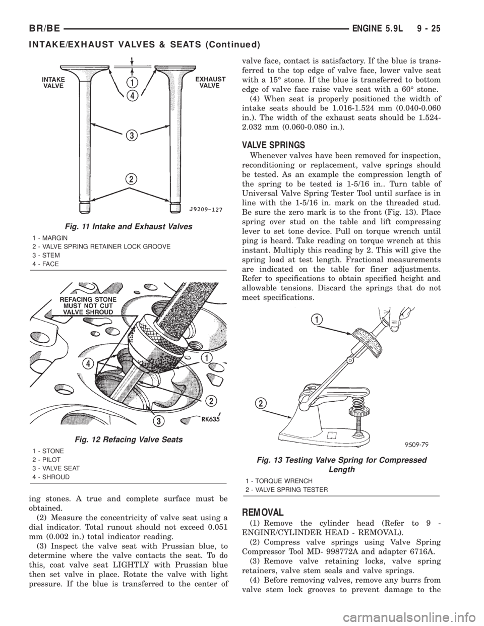
ing stones. A true and complete surface must be
obtained.
(2) Measure the concentricity of valve seat using a
dial indicator. Total runout should not exceed 0.051
mm (0.002 in.) total indicator reading.
(3) Inspect the valve seat with Prussian blue, to
determine where the valve contacts the seat. To do
this, coat valve seat LIGHTLY with Prussian blue
then set valve in place. Rotate the valve with light
pressure. If the blue is transferred to the center ofvalve face, contact is satisfactory. If the blue is trans-
ferred to the top edge of valve face, lower valve seat
with a 15É stone. If the blue is transferred to bottom
edge of valve face raise valve seat with a 60É stone.
(4) When seat is properly positioned the width of
intake seats should be 1.016-1.524 mm (0.040-0.060
in.). The width of the exhaust seats should be 1.524-
2.032 mm (0.060-0.080 in.).
VALVE SPRINGS
Whenever valves have been removed for inspection,
reconditioning or replacement, valve springs should
be tested. As an example the compression length of
the spring to be tested is 1-5/16 in.. Turn table of
Universal Valve Spring Tester Tool until surface is in
line with the 1-5/16 in. mark on the threaded stud.
Be sure the zero mark is to the front (Fig. 13). Place
spring over stud on the table and lift compressing
lever to set tone device. Pull on torque wrench until
ping is heard. Take reading on torque wrench at this
instant. Multiply this reading by 2. This will give the
spring load at test length. Fractional measurements
are indicated on the table for finer adjustments.
Refer to specifications to obtain specified height and
allowable tensions. Discard the springs that do not
meet specifications.
REMOVAL
(1) Remove the cylinder head (Refer to 9 -
ENGINE/CYLINDER HEAD - REMOVAL).
(2) Compress valve springs using Valve Spring
Compressor Tool MD- 998772A and adapter 6716A.
(3) Remove valve retaining locks, valve spring
retainers, valve stem seals and valve springs.
(4) Before removing valves, remove any burrs from
valve stem lock grooves to prevent damage to the
Fig. 11 Intake and Exhaust Valves
1 - MARGIN
2 - VALVE SPRING RETAINER LOCK GROOVE
3 - STEM
4-FACE
Fig. 12 Refacing Valve Seats
1-STONE
2 - PILOT
3 - VALVE SEAT
4 - SHROUD
Fig. 13 Testing Valve Spring for Compressed
Length
1 - TORQUE WRENCH
2 - VALVE SPRING TESTER
BR/BEENGINE 5.9L 9 - 25
INTAKE/EXHAUST VALVES & SEATS (Continued)