fuse chart DODGE RAM 2002 Service Repair Manual
[x] Cancel search | Manufacturer: DODGE, Model Year: 2002, Model line: RAM, Model: DODGE RAM 2002Pages: 2255, PDF Size: 62.07 MB
Page 440 of 2255
3. If not OK, repair the open ground circuit to ground
as required.
(3) Reconnect the battery negative cable. Turn the
park lamps on with the headlamp switch. Rotate the
panel lamps dimmer thumbwheel on the headlamp
switch upward to just before the interior lamps
detent. Check for battery voltage at the fused panel
lamps dimmer switch signal circuit cavity of the
instrument panel wire harness connector for the
heated seat switch. If OK, replace the faulty heated
seat switch. If not OK, repair the open fused panel
lamps dimmer switch signal circuit to the fuse in the
Junction Block (JB) as required.
(4) Check the fused ignition switch output (run)
fuse in the Junction Block (JB). If OK, go to Step 5.
If not OK, repair the shorted circuit or component as
required and replace the faulty fuse.
(5) Turn the ignition switch to the On position.
Check for battery voltage at the fused ignition switch
output (run) fuse in the JB. If OK, go to Step 6. If
not OK, repair the open fused ignition switch output
(run) circuit to the ignition switch as required.
(6) Disconnect and isolate the battery negative
cable. Remove the heated seat switch and bezel unit
from the instrument panel. Disconnect the instru-
ment panel wire harness connector from the connec-
tor receptacle on the back of the heated seat switch
to be tested. Reconnect the battery negative cable.
Turn the ignition switch to the On position. Check
for battery voltage at the fused ignition switch out-
put (run) circuit cavity of the instrument panel wire
harness connector for the heated seat switch. If OK,
go to Step 7. If not OK, repair the open fused ignition
switch output (run) circuit to the JB fuse as required.
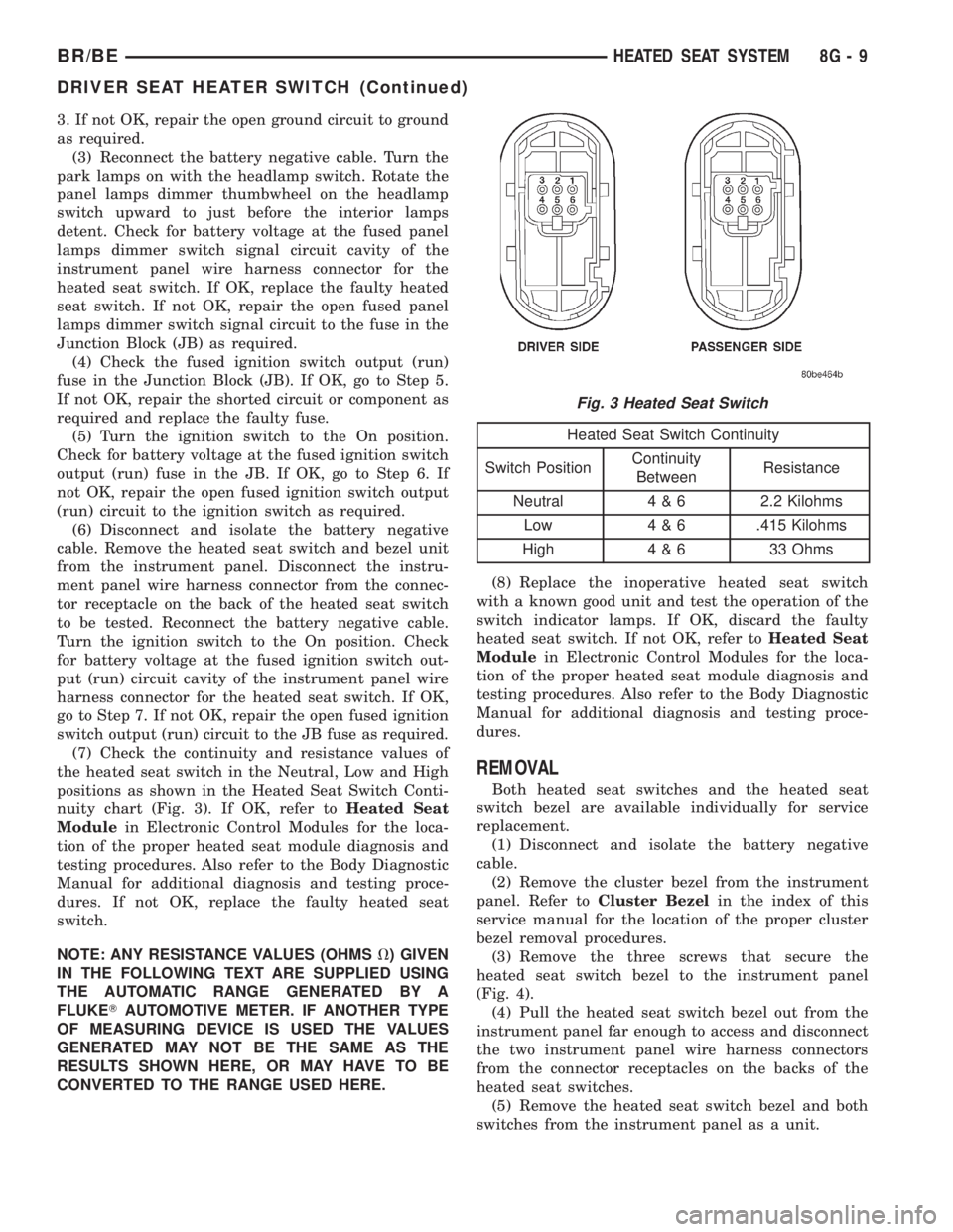
(7) Check the continuity and resistance values of
the heated seat switch in the Neutral, Low and High
positions as shown in the Heated Seat Switch Conti-
nuity chart (Fig. 3). If OK, refer toHeated Seat
Modulein Electronic Control Modules for the loca-
tion of the proper heated seat module diagnosis and
testing procedures. Also refer to the Body Diagnostic
Manual for additional diagnosis and testing proce-
dures. If not OK, replace the faulty heated seat
switch.
NOTE: ANY RESISTANCE VALUES (OHMSV) GIVEN
IN THE FOLLOWING TEXT ARE SUPPLIED USING
THE AUTOMATIC RANGE GENERATED BY A
FLUKETAUTOMOTIVE METER. IF ANOTHER TYPE
OF MEASURING DEVICE IS USED THE VALUES
GENERATED MAY NOT BE THE SAME AS THE
RESULTS SHOWN HERE, OR MAY HAVE TO BE
CONVERTED TO THE RANGE USED HERE.
Heated Seat Switch Continuity
Switch PositionContinuity
BetweenResistance
Neutral 4 & 6 2.2 Kilohms
Low 4 & 6 .415 Kilohms
High 4 & 6 33 Ohms
(8) Replace the inoperative heated seat switch
with a known good unit and test the operation of the
switch indicator lamps. If OK, discard the faulty
heated seat switch. If not OK, refer toHeated Seat
Modulein Electronic Control Modules for the loca-
tion of the proper heated seat module diagnosis and
testing procedures. Also refer to the Body Diagnostic
Manual for additional diagnosis and testing proce-
dures.
REMOVAL
Both heated seat switches and the heated seat
switch bezel are available individually for service
replacement.
(1) Disconnect and isolate the battery negative
cable.
(2) Remove the cluster bezel from the instrument
panel. Refer toCluster Bezelin the index of this
service manual for the location of the proper cluster
bezel removal procedures.
(3) Remove the three screws that secure the
heated seat switch bezel to the instrument panel
(Fig. 4).
(4) Pull the heated seat switch bezel out from the
instrument panel far enough to access and disconnect
the two instrument panel wire harness connectors
from the connector receptacles on the backs of the
heated seat switches.
(5) Remove the heated seat switch bezel and both
switches from the instrument panel as a unit.
Fig. 3 Heated Seat Switch
BR/BEHEATED SEAT SYSTEM 8G - 9
DRIVER SEAT HEATER SWITCH (Continued)
Page 449 of 2255
involves inoperative heated seat switch indicator
lamps and the heated seat elements do heat, go to
Step 8. If the problem being diagnosed involves a
heated seat switch indicator lamp that remains illu-
minated after the heated seat has been turned Off,
refer toHeated Seat Modulein Electronic Control
Modules for the location of the proper heated seat
module diagnosis and testing procedures. Also refer
to the Body Diagnostic Manual for additional diagno-
sis and testing procedures.
(2) Disconnect and isolate the battery negative
cable. Remove the heated seat switch and bezel unit
from the instrument panel. Disconnect the instru-
ment panel wire harness connector from the connec-
tor receptacle on the back of the heated seat switch
to be tested. Check for continuity between the ground
circuit cavity of the instrument panel wire harness
connector for the heated seat switch and a good
ground. There should be continuity. If OK, go to Step
3. If not OK, repair the open ground circuit to ground
as required.
(3) Reconnect the battery negative cable. Turn the
park lamps on with the headlamp switch. Rotate the
panel lamps dimmer thumbwheel on the headlamp
switch upward to just before the interior lamps
detent. Check for battery voltage at the fused panel
lamps dimmer switch signal circuit cavity of the
instrument panel wire harness connector for the
heated seat switch. If OK, replace the faulty heated
seat switch. If not OK, repair the open fused panel
lamps dimmer switch signal circuit to the fuse in the
Junction Block (JB) as required.
(4) Check the fused ignition switch output (run)
fuse in the Junction Block (JB). If OK, go to Step 5.
If not OK, repair the shorted circuit or component as
required and replace the faulty fuse.
(5) Turn the ignition switch to the On position.
Check for battery voltage at the fused ignition switch
output (run) fuse in the JB. If OK, go to Step 6. If
not OK, repair the open fused ignition switch output
(run) circuit to the ignition switch as required.
(6) Disconnect and isolate the battery negative
cable. Remove the heated seat switch and bezel unit
from the instrument panel. Disconnect the instru-
ment panel wire harness connector from the connec-
tor receptacle on the back of the heated seat switch
to be tested. Reconnect the battery negative cable.
Turn the ignition switch to the On position. Check
for battery voltage at the fused ignition switch out-
put (run) circuit cavity of the instrument panel wire
harness connector for the heated seat switch. If OK,
go to Step 7. If not OK, repair the open fused ignition
switch output (run) circuit to the JB fuse as required.
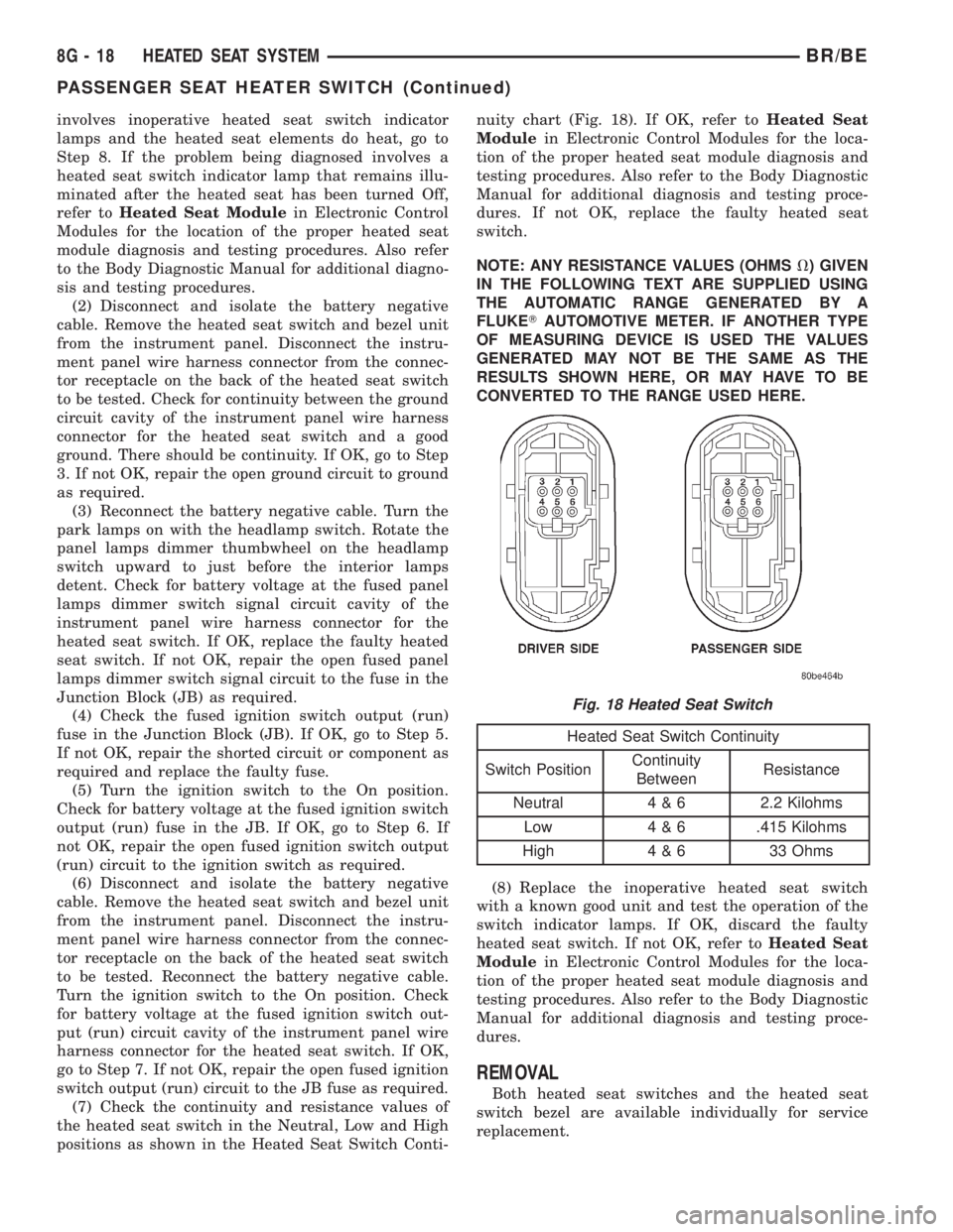
(7) Check the continuity and resistance values of
the heated seat switch in the Neutral, Low and High
positions as shown in the Heated Seat Switch Conti-nuity chart (Fig. 18). If OK, refer toHeated Seat
Modulein Electronic Control Modules for the loca-
tion of the proper heated seat module diagnosis and
testing procedures. Also refer to the Body Diagnostic
Manual for additional diagnosis and testing proce-
dures. If not OK, replace the faulty heated seat
switch.
NOTE: ANY RESISTANCE VALUES (OHMSV) GIVEN
IN THE FOLLOWING TEXT ARE SUPPLIED USING
THE AUTOMATIC RANGE GENERATED BY A
FLUKETAUTOMOTIVE METER. IF ANOTHER TYPE
OF MEASURING DEVICE IS USED THE VALUES
GENERATED MAY NOT BE THE SAME AS THE
RESULTS SHOWN HERE, OR MAY HAVE TO BE
CONVERTED TO THE RANGE USED HERE.
Heated Seat Switch Continuity
Switch PositionContinuity
BetweenResistance
Neutral 4 & 6 2.2 Kilohms
Low 4 & 6 .415 Kilohms
High 4 & 6 33 Ohms
(8) Replace the inoperative heated seat switch
with a known good unit and test the operation of the
switch indicator lamps. If OK, discard the faulty
heated seat switch. If not OK, refer toHeated Seat
Modulein Electronic Control Modules for the loca-
tion of the proper heated seat module diagnosis and
testing procedures. Also refer to the Body Diagnostic
Manual for additional diagnosis and testing proce-
dures.
REMOVAL
Both heated seat switches and the heated seat
switch bezel are available individually for service
replacement.
Fig. 18 Heated Seat Switch
8G - 18 HEATED SEAT SYSTEMBR/BE
PASSENGER SEAT HEATER SWITCH (Continued)
Page 486 of 2255
(10) Disconnect and isolate the battery negative
cable. Remove the instrument cluster. Check for con-
tinuity between the ground circuit (Z2) cavity of the
instrument panel wire harness connector (Connector
C1) and a good ground. There should be continuity. If
OK, refer to ACTUATOR TEST . If not OK, repair
the open ground circuit to ground (G200) as required.
ACTUATOR TEST
WARNING: ON VEHICLES EQUIPPED WITH AIR-
BAGS, DISABLE THE AIRBAG SYSTEM BEFORE
ATTEMPTING ANY STEERING WHEEL, STEERING
COLUMN, OR INSTRUMENT PANEL COMPONENT
DIAGNOSIS OR SERVICE. DISCONNECT AND ISO-
LATE THE BATTERY NEGATIVE (GROUND) CABLE,
THEN WAIT TWO MINUTES FOR THE AIRBAG SYS-
TEM CAPACITOR TO DISCHARGE BEFORE PER-
FORMING FURTHER DIAGNOSIS OR SERVICE. THIS
IS THE ONLY SURE WAY TO DISABLE THE AIRBAG
SYSTEM. FAILURE TO TAKE THE PROPER PRE-
CAUTIONS COULD RESULT IN ACCIDENTAL AIR-
BAG DEPLOYMENT AND POSSIBLE PERSONAL
INJURY.
The instrument cluster actuator test will put the
instrument cluster into its self-diagnostic mode. In
this mode the instrument cluster can perform a self-
diagnostic test that will confirm that the instrument
cluster circuitry, the gauges, and the CCD data bus
message-controlled indicators are capable of operat-
ing as designed. During the actuator test the instru-
ment cluster circuitry position each of the gaugeneedles at various calibration points, illuminate each
of the segments in the Vacuum-Fluorescent Display
(VFD), and turn all of the CCD data bus message-
controlled indicators on and off.
Successful completion of the actuator test will con-
firm that the instrument cluster is operational. How-
ever, there may still be a problem with the CCD data
bus, the Powertrain Control Module (PCM), the
Engine Control Module (ECM), the Airbag Control
Module (ACM), the Controller Anti-lock Brake (CAB),
or the inputs to one of these electronic control mod-
ules. Use a DRBIIItscan tool to diagnose these com-
ponents. Refer to the appropriate diagnostic
information.
(1) Begin the test with the ignition switch in the
Off position.
(2) Depress the odometer/trip odometer switch but-
ton.
(3) While still holding the odometer/trip odometer
switch button depressed, turn the ignition switch to
the On position, but do not start the engine.
(4) Keep the odometer/trip odometer switch button
depressed for about ten seconds, untilCHEC
appears in the odometer display, then release the
odometer/trip odometer switch button.
(5) A series of three-digit numeric failure messages
may appear in the odometer display, depending upon
the failure mode. If a failure message appears, refer
to the Instrument Cluster Failure Message chart for
the description and proper correction. If no failure
message appears, the actuator test will proceed as
described in Step 6.
INSTRUMENT CLUSTER FAILURE MESSAGE
Message Description Correction
110 A failure has been identified in the cluster
CPU, RAM, or EEPROM.1. Replace the faulty cluster.
900 The CCD data bus is not operational. 1. Check the CCD data bus connections at the
cluster.
2. Check the cluster fuses.
3. Check the CCD data bus bias.
4. Check the CCD data bus voltage.
5. Check the CCD data bus terminations.
920 The cluster is not receiving a vehicle speed
message from the PCM.1. Check the PCM software level and reflash if
required.
2. Use a DRBIIITscan tool to verify that the
vehicle speed message is being sent by the
PCM.
921 The cluster is not receiving a distance pulse
message from the PCM.1. Check the PCM software level and reflash if
required.
2. Use a DRBIIITscan tool to verify that the
distance pulse message is being sent by the
PCM.
BR/BEINSTRUMENT CLUSTER 8J - 7
INSTRUMENT CLUSTER (Continued)
Page 563 of 2255
will return to the last function being displayed before
the ignition was turned to the Off position. With the
ignition switch in the On position, momentarily
depressing and releasing the Step push button switch
will cause the compass-mini-trip computer to change
its mode of operation, and momentarily depressing
and releasing the U.S./Metric push button will cause
the unit to toggle between U.S. and Metric measure-
ments. While in either compass mode, depressing the
U.S./Metric push button for more than ten seconds
will toggle the display between the compass/temper-
ature and the compass/compass in degrees modes.
This compass mini-trip computer features several
functions that can be reset. If both the Step and U.S./
Metric push buttons are depressed at the same time
with the ignition switch in the On position, the trip
computer information that can be reset is reset.
Depressing and releasing the Step and U.S./Metric
push buttons at the same time for more than 100
milliseconds, but not more than one second while in
any display mode (except the compass/temperature
mode) will cause a local reset. A local reset affects
only the function currently displayed. See the Reset
Chart below for more information on this feature.
Performing a local reset while in the compass/tem-
perature mode enters the module into the compass
variance setting mode.
Depressing and releasing the Step and U.S./Metric
push buttons at the same time for more than two
seconds while in any display mode (except the com-
pass/temperature mode) will cause a global reset. A
global reset changes all of the trip computer func-
tions that can be reset.
For more information on the features and control
functions of the compass mini-trip computer, see the
owner's manual in the vehicle glove box.
DIAGNOSIS AND TESTING - COMPASS
MINI-TRIP COMPUTER
If the problem with the compass mini-trip com-
puter module is an inoperative security indicator
lamp, refer toSecurity Indicator Lampin Vehicle
Theft/Security Systems. If the problem with the com-
pass mini-trip computer module is an ªOCº or ªSCº in
the compass/thermometer display, refer toAmbient
Temperature Sensorin this section. If the problem
with the compass mini-trip computer module is an
inaccurate or scrambled display, refer toCMTC Self-
Diagnostic Testin this section. If the problem with
the compass mini-trip computer module is incorrect
Vacuum Fluorescent Display (VFD) dimming levels,
use a DRBtscan tool and the proper Diagnostic Pro-
cedures manual to test for the correct dimming mes-
sage inputs being received from the instrument
cluster over the Chrysler Collision Detection (CCD)
data bus. If the problem is a no-display condition,use the following procedures. For complete circuit
diagrams, refer toOverhead Consolein the Con-
tents of Wiring Diagrams.
(1) Check the fused B(+) fuse in the junction block.
If OK, go to Step 2. If not OK, repair the shorted cir-
cuit or component as required and replace the faulty
fuse.
(2) Check for battery voltage at the fused B(+) fuse
in the junction block. If OK, go to Step 3. If not OK,
repair the open fused B(+) circuit to the battery as
required.
(3) Check the fused ignition switch output (run/
start) fuse in the junction block. If OK, go to Step 4.
If not OK, repair the shorted circuit or component as
required and replace the faulty fuse.
(4) Turn the ignition switch to the On position.
Check for battery voltage at the fused ignition switch
output (run/start) fuse in the junction block. If OK,
go to Step 5. If not OK, repair the open fused ignition
switch output (run/start) circuit to the ignition switch
as required.
(5) Turn the ignition switch to the Off position.
Disconnect and isolate the battery negative cable.
Remove the overhead console. Check for continuity
between the ground circuit cavities of the roof wire
harness connector for the overhead console and a
good ground. There should be continuity. If OK, go to
Step 6. If not OK, repair the open ground circuit to
ground as required.
(6) Connect the battery negative cable. Check for
battery voltage at the fused B(+) circuit cavity of the
roof wire harness connector for the overhead console.
If OK, go to Step 7. If not OK, repair the open fused
B(+) circuit to the junction block fuse as required.
(7) Turn the ignition switch to the On position.
Check for battery voltage at the fused ignition switch
output (run/start) circuit cavity of the roof wire har-
ness connector for the overhead console. If OK, refer
toSelf-Diagnostic Testin the Diagnosis and Test-
ing section of this group for further diagnosis of the
compass mini-trip computer module and the CCD
data bus. If not OK, repair the open fused ignition
switch output (run/start) circuit to the junction block
fuse as required.
CMTC SELF-DIAGNOSTIC TEST
A self-diagnostic test is used to determine that the
compass mini-trip computer module is operating
properly electrically. Initiate the self-diagnostic test
as follows:
(1) With the ignition switch in the Off position,
simultaneously depress and hold the Step button and
the U.S./Metric button.
(2) Turn the ignition switch to the On position.
(3) Continue to hold both buttons depressed until
the compass mini-trip computer module enters the
8M - 10 MESSAGE SYSTEMSBR/BE
COMPASS/MINI-TRIP COMPUTER (Continued)
Page 576 of 2255
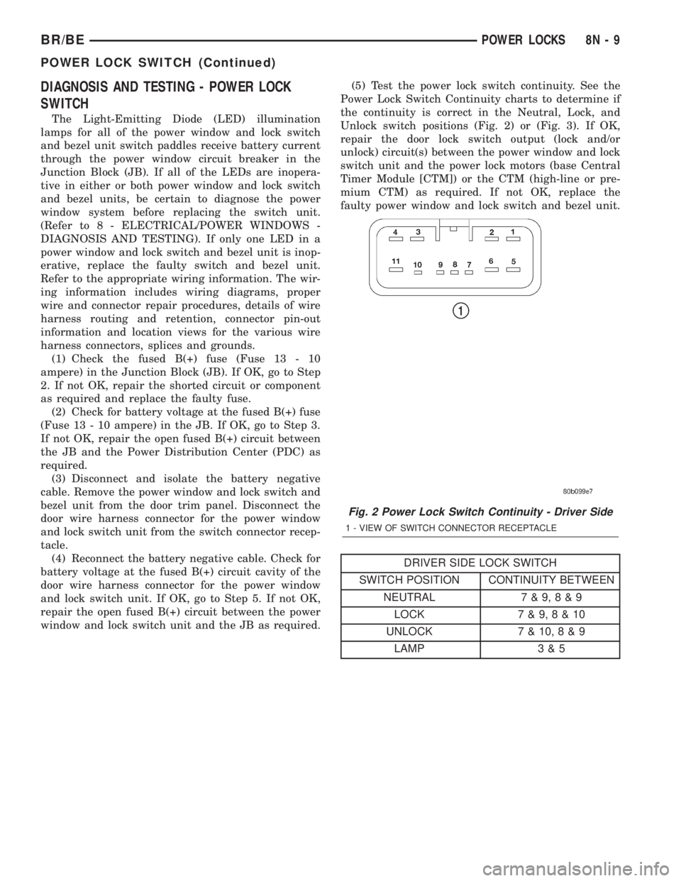
DIAGNOSIS AND TESTING - POWER LOCK
SWITCH
The Light-Emitting Diode (LED) illumination
lamps for all of the power window and lock switch
and bezel unit switch paddles receive battery current
through the power window circuit breaker in the
Junction Block (JB). If all of the LEDs are inopera-
tive in either or both power window and lock switch
and bezel units, be certain to diagnose the power
window system before replacing the switch unit.
(Refer to 8 - ELECTRICAL/POWER WINDOWS -
DIAGNOSIS AND TESTING). If only one LED in a
power window and lock switch and bezel unit is inop-
erative, replace the faulty switch and bezel unit.
Refer to the appropriate wiring information. The wir-
ing information includes wiring diagrams, proper
wire and connector repair procedures, details of wire
harness routing and retention, connector pin-out
information and location views for the various wire
harness connectors, splices and grounds.
(1) Check the fused B(+) fuse (Fuse 13 - 10
ampere) in the Junction Block (JB). If OK, go to Step
2. If not OK, repair the shorted circuit or component
as required and replace the faulty fuse.
(2) Check for battery voltage at the fused B(+) fuse
(Fuse 13 - 10 ampere) in the JB. If OK, go to Step 3.
If not OK, repair the open fused B(+) circuit between
the JB and the Power Distribution Center (PDC) as
required.
(3) Disconnect and isolate the battery negative
cable. Remove the power window and lock switch and
bezel unit from the door trim panel. Disconnect the
door wire harness connector for the power window
and lock switch unit from the switch connector recep-
tacle.
(4) Reconnect the battery negative cable. Check for
battery voltage at the fused B(+) circuit cavity of the
door wire harness connector for the power window
and lock switch unit. If OK, go to Step 5. If not OK,
repair the open fused B(+) circuit between the power
window and lock switch unit and the JB as required.(5) Test the power lock switch continuity. See the
Power Lock Switch Continuity charts to determine if
the continuity is correct in the Neutral, Lock, and
Unlock switch positions (Fig. 2) or (Fig. 3). If OK,
repair the door lock switch output (lock and/or
unlock) circuit(s) between the power window and lock
switch unit and the power lock motors (base Central
Timer Module [CTM]) or the CTM (high-line or pre-
mium CTM) as required. If not OK, replace the
faulty power window and lock switch and bezel unit.
DRIVER SIDE LOCK SWITCH
SWITCH POSITION CONTINUITY BETWEEN
NEUTRAL 7 & 9,8&9
LOCK 7 & 9,8&10
UNLOCK 7 & 10,8&9
LAMP 3 & 5
Fig. 2 Power Lock Switch Continuity - Driver Side
1 - VIEW OF SWITCH CONNECTOR RECEPTACLE
BR/BEPOWER LOCKS 8N - 9
POWER LOCK SWITCH (Continued)
Page 667 of 2255
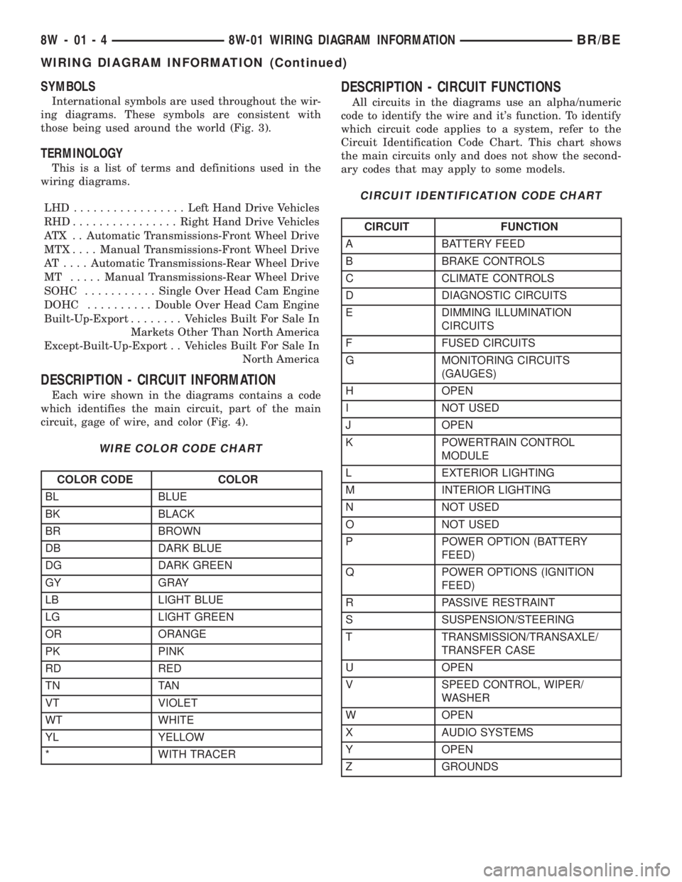
SYMBOLS
International symbols are used throughout the wir-
ing diagrams. These symbols are consistent with
those being used around the world (Fig. 3).
TERMINOLOGY
This is a list of terms and definitions used in the
wiring diagrams.
LHD .................Left Hand Drive Vehicles
RHD................Right Hand Drive Vehicles
ATX . . Automatic Transmissions-Front Wheel Drive
MTX....Manual Transmissions-Front Wheel Drive
AT ....Automatic Transmissions-Rear Wheel Drive
MT .....Manual Transmissions-Rear Wheel Drive
SOHC...........Single Over Head Cam Engine
DOHC..........Double Over Head Cam Engine
Built-Up-Export........ Vehicles Built For Sale In
Markets Other Than North America
Except-Built-Up-Export . . Vehicles Built For Sale In
North America
DESCRIPTION - CIRCUIT INFORMATION
Each wire shown in the diagrams contains a code
which identifies the main circuit, part of the main
circuit, gage of wire, and color (Fig. 4).
WIRE COLOR CODE CHART
COLOR CODE COLOR
BL BLUE
BK BLACK
BR BROWN
DB DARK BLUE
DG DARK GREEN
GY GRAY
LB LIGHT BLUE
LG LIGHT GREEN
OR ORANGE
PK PINK
RD RED
TN TAN
VT VIOLET
WT WHITE
YL YELLOW
* WITH TRACER
DESCRIPTION - CIRCUIT FUNCTIONS
All circuits in the diagrams use an alpha/numeric
code to identify the wire and it's function. To identify
which circuit code applies to a system, refer to the
Circuit Identification Code Chart. This chart shows
the main circuits only and does not show the second-
ary codes that may apply to some models.
CIRCUIT IDENTIFICATION CODE CHART
CIRCUIT FUNCTION
A BATTERY FEED
B BRAKE CONTROLS
C CLIMATE CONTROLS
D DIAGNOSTIC CIRCUITS
E DIMMING ILLUMINATION
CIRCUITS
F FUSED CIRCUITS
G MONITORING CIRCUITS
(GAUGES)
H OPEN
I NOT USED
J OPEN
K POWERTRAIN CONTROL
MODULE
L EXTERIOR LIGHTING
M INTERIOR LIGHTING
N NOT USED
O NOT USED
P POWER OPTION (BATTERY
FEED)
Q POWER OPTIONS (IGNITION
FEED)
R PASSIVE RESTRAINT
S SUSPENSION/STEERING
T TRANSMISSION/TRANSAXLE/
TRANSFER CASE
U OPEN
V SPEED CONTROL, WIPER/
WASHER
W OPEN
X AUDIO SYSTEMS
Y OPEN
Z GROUNDS
8W - 01 - 4 8W-01 WIRING DIAGRAM INFORMATIONBR/BE
WIRING DIAGRAM INFORMATION (Continued)
Page 2245 of 2255
SENSOR - REMOVAL, FUEL LEVEL
SENDING UNIT.......................14-7
SENSOR - REMOVAL, O2..............14-46
SENSOR - REMOVAL, REAR WHEEL
SPEED..............................5-40
SENSOR - REMOVAL, WATER IN FUEL....14-89
SENSOR RETURN - DESCRIPTION.......8E-17
SENSOR/SWITCH - INSTALLATION, OIL
PRESSURE.........................9-181
SENSOR/SWITCH - REMOVAL, OIL
PRESSURE.........................9-181
SEPARATOR - DESCRIPTION, FUEL
FILTER / WATER .....................14-63
SEPARATOR - INSTALLATION, FUEL
FILTER / WATER .....................14-65
SEPARATOR - OPERATION, FUEL FILTER
/ WATER ...........................14-63
SEPARATOR - REMOVAL, FUEL FILTER /
WATER.............................14-64
SERVO - ASSEMBLY, FRONT.....21-164,21-335
SERVO - ASSEMBLY, REAR......21-207,21-379
SERVO - CLEANING, FRONT.....21-164,21-334
SERVO - CLEANING, REAR......21-207,21-379
SERVO - DESCRIPTION, FRONT . . 21-164,21-334
SERVO - DESCRIPTION, REAR . . . 21-207,21-378
SERVO - DESCRIPTION, SPEED
CONTROL...........................8P-6
SERVO - DISASSEMBLY, FRONT . . 21-164,21-334
SERVO - DISASSEMBLY, REAR . . . 21-207,21-378
SERVO - INSPECTION, FRONT.....21-164,21-335
SERVO - OPERATION, FRONT....21-164,21-334
SERVO - OPERATION, REAR.....21-207,21-378
SERVO - OPERATION, SPEED CONTROL . . . 8P-6
SEVERAL LOADS - STANDARD
PROCEDURE, TESTING FOR A SHORT
TO GROUND ON FUSES POWERING . . . 8W-01-9
SHAFT - ASSEMBLY, PLANETARY
GEARTRAIN/OUTPUT...........21-199,21-371
SHAFT - DESCRIPTION, PLANETARY
GEARTRAIN/OUTPUT...........21-197,21-369
SHAFT - DIAGNOSIS AND TESTING,
PROPELLER...........................3-1
SHAFT - DISASSEMBLY, PLANETARY
GEARTRAIN/OUTPUT...........21-198,21-369
SHAFT - FRONT - INSTALLATION,
PROPELLER...........................3-7
SHAFT - FRONT - REMOVAL,
PROPELLER...........................3-6
SHAFT - INSPECTION, PLANETARY
GEARTRAIN/OUTPUT...........21-199,21-371
SHAFT - INSTALLATION, PITMAN........19-25
SHAFT - INSTALLATION, WORM.........19-31
SHAFT - OPERATION, PLANETARY
GEARTRAIN/OUTPUT...........21-197,21-369
SHAFT - REAR - INSTALLATION,
PROPELLER...........................3-7
SHAFT - REAR - REMOVAL, PROPELLER....3-7
SHAFT - REMOVAL, PITMAN............19-24
SHAFT - REMOVAL, WORM............19-30
SHAFT - STANDARD PROCEDURES,
PROPELLER...........................3-3
SHAFT FRONT BEARING -
INSTALLATION, OUTPUT........21-171,21-342
SHAFT FRONT BEARING - REMOVAL,
OUTPUT.....................21-171,21-342
SHAFT REAR BEARING - INSTALLATION,
OUTPUT.....................21-172,21-343
SHAFT REAR BEARING - REMOVAL,
OUTPUT.....................21-171,21-343
SHAFT SEAL - INSTALLATION, FRONT
OUTPUT.....................21-461,21-498
SHAFT SEAL - INSTALLATION, PITMAN
. . . 19-26
SHAFT SEAL - REMOVAL, FRONT
OUTPUT
.....................21-461,21-498
SHAFT SEAL - REMOVAL, PITMAN
.......19-25
SHAFT SEALS - INSTALLATION, AXLE
.....3-31
SHAFT SEALS - REMOVAL, AXLE
.........3-31
SHAFT, SPECIAL TOOLS - PROPELLER
......3-6
SHAFT, SPECIFICATIONS - PROPELLER
.....3-6
SHAFTS - INSTALLATION,
AXLE
..................3-123,3-29,3-62,3-94
SHAFTS - INTERMEDIATE - REMOVAL,
AXLE
...............................3-30
SHAFTS - REMOVAL, AXLE
. 3-123,3-29,3-62,3-94
SHIELD - INSTALLATION, REAR SPLASH
. . 23-96
SHIELD - REMOVAL, REAR SPLASH
......23-96
SHIELDS - DESCRIPTION, HEAT
.........11-10SHIELDS - INSTALLATION, FRONT END
SPLASH............................23-92
SHIELDS - INSTALLATION, HEAT........11-10
SHIELDS - REMOVAL, FRONT END
SPLASH............................23-92
SHIELDS - REMOVAL, HEAT............11-10
SHIFT BOOT - INSTALLATION, 4WD
FLOOR............................23-122
SHIFT BOOT - MANUAL TRANSMISSION
- INSTALLATION....................23-122
SHIFT BOOT - MANUAL TRANSMISSION
- REMOVAL........................23-122
SHIFT BOOT - REMOVAL, 4WD FLOOR . . . 23-122
SHIFT COVER - NV4500 - INSTALLATION . . 21-45
SHIFT COVER - NV4500 - REMOVAL.....21-45
SHIFT COVER - NV5600 - INSTALLATION . . 21-86
SHIFT COVER - NV5600 - REMOVAL.....21-86
SHIFT INDICATOR (TRANSFER CASE) -
DESCRIPTION.......................8J-28
SHIFT INDICATOR (TRANSFER CASE) -
OPERATION.........................8J-28
SHIFT LEVER - ADJUSTMENT....21-463,21-500
SHIFT LEVER - INSTALLATION . . . 21-462,21-500
SHIFT LEVER - INSTALLATION, GEAR.....19-15
SHIFT LEVER - REMOVAL.......21-462,21-499
SHIFT LEVER - REMOVAL, GEAR........19-14
SHIFT MECHANISM - DESCRIPTION....21-208,
21-379
SHIFT MECHANISM - NV4500 -
INSTALLATION........................21-44
SHIFT MECHANISM - NV4500 -
REMOVAL..........................21-43
SHIFT MECHANISM - OPERATION......21-208,
21-379
SHOCK - DIAGNOSIS AND TESTING . . . 2-11,2-22
SHOCK - DIAGNOSIS AND TESTING,
SPRING.............................2-25
SHOCK - INSTALLATION........2-11,2-22,2-27
SHOCK - REMOVAL............2-11,2-22,2-27
SHOES - ADJUSTMENT, PARKING BRAKE . . 5-33
SHOES - INSTALLATION................5-32
SHOES - REMOVAL....................5-32
SHORT TO GROUND - STANDARD
PROCEDURE, TESTING FOR A........8W-01-9
SHORT TO GROUND ON FUSES
POWERING SEVERAL LOADS -
STANDARD PROCEDURE, TESTING
FOR A ...........................8W-01-9
SHUTFACE HANDLE - INSTALLATION.....23-83
SHUTFACE HANDLE - REMOVAL.........23-83
SIDE MOLDINGS - INSTALLATION, BODY . . 23-87
SIDE MOLDINGS - REMOVAL, BODY.....23-86
SIDE PANEL SPEAKER - INSTALLATION,
REAR CAB..........................8A-20
SIDE PANEL SPEAKER - REMOVAL,
REAR CAB..........................8A-20
SIDE VIEW MIRROR - INSTALLATION.....23-98
SIDE VIEW MIRROR - LOW MOUNTED -
INSTALLATION.......................23-98
SIDE VIEW MIRROR - LOW MOUNTED -
REMOVAL..........................23-98
SIDE VIEW MIRROR - REMOVAL........23-97
SIDE VIEW MIRROR FLAG -
INSTALLATION.......................23-75
SIDE VIEW MIRROR FLAG - REMOVAL . . . 23-74
SIDE VIEW MIRROR GLASS -
INSTALLATION.......................23-98
SIDE VIEW MIRROR GLASS - REMOVAL . . 23-98
SIDEVIEW MIRROR - DESCRIPTION......8N-14
SIDEVIEW MIRROR - DIAGNOSIS AND
TESTING...........................8N-14
SIDEVIEW MIRROR - OPERATION.......8N-14
SIDEVIEW MIRROR - REMOVAL.........8N-15
SIGNAL & HAZARD WARNING SYSTEM -
DESCRIPTION, TURN..................8L-2
SIGNAL & HAZARD WARNING SYSTEM -
DIAGNOSIS AND TESTING, TURN.........8L-3
SIGNAL & HAZARD WARNING SYSTEM -
OPERATION, TURN....................8L-2
SIGNAL CANCEL CAM - DESCRIPTION,
TURN
..............................8L-31
SIGNAL CANCEL CAM - OPERATION,
TURN
..............................8L-31
SIGNAL GROUND - DESCRIPTION
.......8E-17
SIGNAL INDICATOR - DESCRIPTION,
TURN
..............................8J-32
SIGNAL INDICATOR - DIAGNOSIS AND
TESTING, TURN
......................8J-32SIGNAL INDICATOR - OPERATION, TURN . . 8J-32
SIGNAL LAMP - INSTALLATION,
PARK/TURN.........................8L-29
SIGNAL LAMP - REMOVAL, PARK/TURN . . 8L-29
SIGNAL LAMP UNIT - INSTALLATION,
PARK/TURN.........................8L-29
SIGNAL LAMP UNIT - REMOVAL,
PARK/TURN.........................8L-29
SILENCER PAD - INSTALLATION........23-104
SILENCER PAD - REMOVAL...........23-104
SILL TRIM - INSTALLATION, DOOR.....23-121
SILL TRIM - REMOVAL, DOOR.........23-121
SINGLE CARDAN UNIVERSAL JOINTS -
ASSEMBLY...........................3-9
SINGLE CARDAN UNIVERSAL JOINTS -
DISASSEMBLY.........................3-8
SINGLE CARDAN UNIVERSAL JOINTS -
INSTALLATION........................3-35
SINGLE CARDAN UNIVERSAL JOINTS -
REMOVAL...........................3-34
SKID PLATE - INSTALLATION, TRANSFER
CASE..............................13-11
SKID PLATE - REMOVAL, TRANSFER
CASE..............................13-11
SLAM BUMPER - INSTALLATION........23-67
SLAM BUMPER - REMOVAL............23-67
SMOKE DIAGNOSIS CHARTS -
DIAGNOSIS AND TESTING.............9-118
SOLENOID - DESCRIPTION......21-208,21-380
SOLENOID - DESCRIPTION, EVAP/PURGE . 25-33
SOLENOID - INSTALLATION, EVAP/
PURGE.............................25-34
SOLENOID - OPERATION........21-209,21-381
SOLENOID - OPERATION, EVAP/PURGE . . . 25-33
SOLENOID - REMOVAL, EVAP/PURGE.....25-33
SOLID LIFTERS/TAPPETS - CLEANING....9-164
SOLID LIFTERS/TAPPETS - INSPECTION . . 9-165
SOLID LIFTERS/TAPPETS -
INSTALLATION.......................9-165
SOLID LIFTERS/TAPPETS - REMOVAL....9-164
SPARE TIRE - DESCRIPTION............22-10
SPARE TIRE - TEMPORARY -
DESCRIPTION........................22-6
SPARK PLUG - CLEANING..............8I-20
SPARK PLUG - DESCRIPTION...........8I-16
SPARK PLUG - INSTALLATION...........8I-20
SPARK PLUG - OPERATION.............8I-16
SPARK PLUG - REMOVAL..............8I-19
SPARK PLUG CABLE - DESCRIPTION.....8I-20
SPARK PLUG CABLE - INSTALLATION.....8I-21
SPARK PLUG CABLE - OPERATION.......8I-20
SPARK PLUG CABLE - REMOVAL........8I-21
SPARK PLUG CABLE ORDER, 8.0L V-10
ENGINE..............................8I-3
SPARK PLUG CABLE RESISTANCE,
SPECIFICATIONS......................8I-3
SPARK PLUG CABLES - DIAGNOSIS AND
TESTING............................8I-20
SPARK PLUG CONDITIONS - DIAGNOSIS
AND TESTING........................8I-17
SPARK PLUGS, SPECIFICATIONS..........8I-3
SPEAKER - DESCRIPTION..............8A-17
SPEAKER - DIAGNOSIS AND TESTING....8A-17
SPEAKER - INSTALLATION, A-PILLAR
TWEETER..........................8A-19
SPEAKER - INSTALLATION, FRONT DOOR . 8A-19
SPEAKER - INSTALLATION, REAR CAB
SIDE PANEL........................8A-20
SPEAKER - INSTALLATION, REAR DOOR . . 8A-21
SPEAKER - OPERATION...............8A-17
SPEAKER - REMOVAL, A-PILLAR
TWEETER..........................8A-18
SPEAKER - REMOVAL, FRONT DOOR.....8A-19
SPEAKER - REMOVAL, REAR CAB SIDE
PANEL.............................8A-20
SPEAKER - REMOVAL, REAR DOOR......8A-20
SPECIAL TOOL, SPECIAL TOOLS -
OVERHEAD CONSOLE.................8M-9
SPECIFICATIONS - 2002 BR/BE PAINT
COLOR CODES.....................23-129
SPECIFICATIONS - 5.9L DIESEL.........9-127
SPECIFICATIONS - 5.9L ENGINE..........9-13
SPECIFICATIONS - 8.OL ENGINE
..........9-68
SPECIFICATIONS - A/C APPLICATION
TABLE
..............................24-7
SPECIFICATIONS - ALIGNMENT
...........2-6
SPECIFICATIONS - BASE BRAKE
...........5-2
SPECIFICATIONS - BATTERY
.............8F-6
28 INDEXBR/BE
Description Group-Page Description Group-Page Description Group-Page