change time DODGE RAM 2002 Service Repair Manual
[x] Cancel search | Manufacturer: DODGE, Model Year: 2002, Model line: RAM, Model: DODGE RAM 2002Pages: 2255, PDF Size: 62.07 MB
Page 28 of 2255
STANDARD PROCEDURE
STANDARD PROCEDURES - ALIGNMENT I.F.S.
Before each alignment reading the vehicle should
be jounced (rear first, then front). Grasp each
bumper at the center and jounce the vehicle up and
down several times. Always release the bumper in
the down position.Set the front end alignment to
specifications while the vehicle is in its NOR-
MALLY LOADED CONDITION.
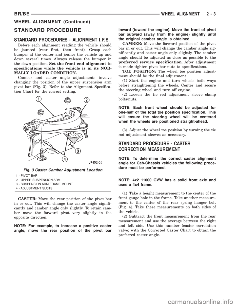
Camber and caster angle adjustments involve
changing the position of the upper suspension arm
pivot bar (Fig. 3). Refer to the Alignment Specifica-
tion Chart for the correct setting.
CASTER:Move the rear position of the pivot bar
in or out. This will change the caster angle signifi-
cantly and camber angle only slightly. To retain cam-
ber move the forward pivot very slightly in the
opposite direction.
NOTE: For example, to increase a positive caster
angle, move the rear position of the pivot barinward (toward the engine). Move the front of pivot
bar outward (away from the engine) slightly until
the original camber angle is obtained.
CAMBER:Move the forward position of the pivot
bar in or out. This will change the camber angle sig-
nificantly and caster angle only slightly. The camber
angle should be adjusted as close as possible to the
preferred service specification. After adjustment
is made tighten pivot bar nuts to specifications.
TOE POSITION:The wheel toe position adjust-
ment should be the final adjustment.
(1) Start the engine and turn wheels both ways
before straightening the wheels. Center and secure
the steering wheel and turn off engine.
(2) Loosen the tie rod adjustment sleeve clamp
bolts/nuts.
NOTE: Each front wheel should be adjusted for
one-half of the total toe position specification. This
will ensure the steering wheel will be centered
when the wheels are positioned straight-ahead.
(3) Adjust the wheel toe position by turning the tie
rod adjustment sleeves as necessary.
STANDARD PROCEDURE - CASTER
CORRECTION MEASUREMENT
NOTE: To determine the correct caster alignment
angle for Cab-Chassis vehicles the following proce-
dure must be performed.
NOTE: 4x2 11000 GVW has a solid front axle and
uses a 4x4 frame.
(1) Take a height measurement to the center of the
front gauge hole in the frame. Take another measure-
ment to the center of the rear spring hanger bolt
(Fig. 4). Take these measurements on both sides of
the vehicle.
(2) Subtract the front measurement from the rear
measurement and use the average between the right
and left side. Use this number (caster correlation
valve) with the Corrected Caster Chart to obtain the
preferred caster angle.
Fig. 3 Caster Camber Adjustment Location
1 - PIVOT BAR
2 - UPPER SUSPENSION ARM
3 - SUSPENSION ARM FRAME MOUNT
4 - ADJUSTMENT SLOTS
BR/BEWHEEL ALIGNMENT 2 - 3
WHEEL ALIGNMENT (Continued)
Page 30 of 2255
CORRECTED CASTER CHART-CAB CHASSIS
Caster
Correlation
Value
(inches)4x2 8800
lb. GVW
134.7 in.
wheel
base4x4 8800
lb. GVW
4x2 & 4x4
11000 lb.
GVW
134.7 &
138.7 in.
wheel
base4x2 & 4x4
11000 lb.
GVW 162.7
in. wheel
base
Caster 1
deg.Caster 1
deg.Caster 1
deg.
25.00 4.27É 3.77É 3.81É
24.75 4.39É 3.89É 3.91É
24.50 4.51É 4.01É 4.01É
24.25 4.64É 4.14É 4.11É
24.00 4.76É 4.26É 4.21É
23.75 4.88É 4.38É 4.31É
23.50 5.00É 4.50É 4.41É
23.25 5.12É 4.62É 4.51É
23.00 5.25É 4.75É 4.61É
22.75 5.37É 4.87É 4.71É
22.50 5.49É 4.99É 4.81É
22.25 5.61É 5.11É 4.91É
22.00 5.74É 5.24É 5.01É
21.75 5.86É 5.36É 5.11É
21.50 5.98É 5.48É 5.21É
21.25 6.10É 5.60É 5.31É
21.00 6.23É 5.73É 5.41É
20.75 6.33É 5.83É 5.51É
20.50 6.47É 5.97É 5.61É
20.25 6.59É 6.09É 5.71É
0.00 6.71É 6.21É 5.81É
STANDARD PROCEDURE - ALIGNMENT
LINK/COIL SUSPENSION
Before each alignment reading the vehicle should
be jounced (rear first, then front). Grasp each
bumper at the center and jounce the vehicle up and
down several times. Always release the bumper in
the down position.Set the front end alignment to
specifications while the vehicle is in its NOR-
MALLY LOADED CONDITION.
CAMBER:The wheel camber angle is preset and
is not adjustable.
CASTER:Check the caster of the front axle for
correct angle. Be sure the axle is not bent or twisted.Road test the vehicle and make left and right turn.
Observe the steering wheel return-to-center position.
Low caster will cause poor steering wheel returnabil-
ity.
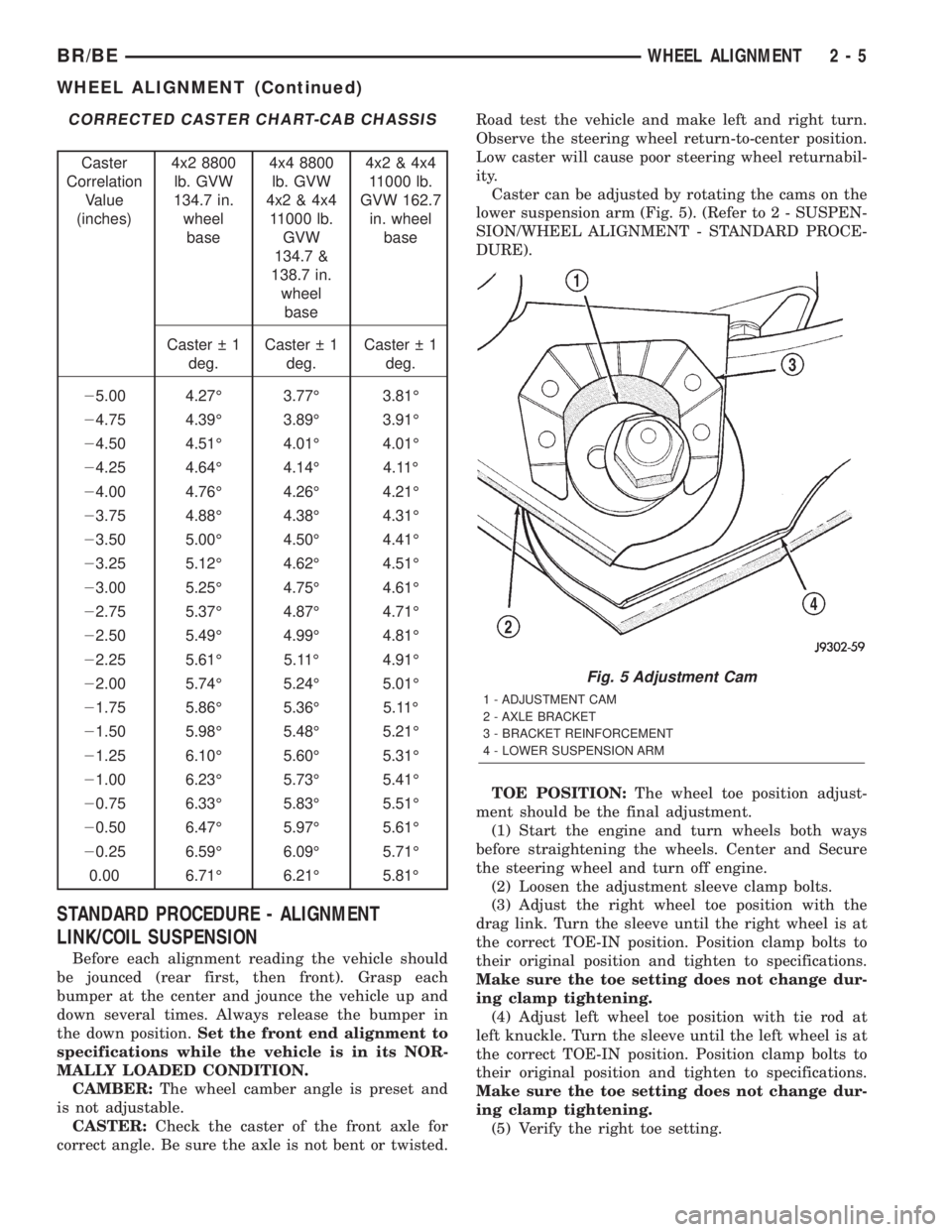
Caster can be adjusted by rotating the cams on the
lower suspension arm (Fig. 5). (Refer to 2 - SUSPEN-
SION/WHEEL ALIGNMENT - STANDARD PROCE-
DURE).
TOE POSITION:The wheel toe position adjust-
ment should be the final adjustment.
(1) Start the engine and turn wheels both ways
before straightening the wheels. Center and Secure
the steering wheel and turn off engine.
(2) Loosen the adjustment sleeve clamp bolts.
(3) Adjust the right wheel toe position with the
drag link. Turn the sleeve until the right wheel is at
the correct TOE-IN position. Position clamp bolts to
their original position and tighten to specifications.
Make sure the toe setting does not change dur-
ing clamp tightening.
(4) Adjust left wheel toe position with tie rod at
left knuckle. Turn the sleeve until the left wheel is at
the correct TOE-IN position. Position clamp bolts to
their original position and tighten to specifications.
Make sure the toe setting does not change dur-
ing clamp tightening.
(5) Verify the right toe setting.
Fig. 5 Adjustment Cam
1 - ADJUSTMENT CAM
2 - AXLE BRACKET
3 - BRACKET REINFORCEMENT
4 - LOWER SUSPENSION ARM
BR/BEWHEEL ALIGNMENT 2 - 5
WHEEL ALIGNMENT (Continued)
Page 195 of 2255
SPONGY PEDAL
A spongy pedal is most often caused by air in the
system. However, thin brake drums or substandard
brake lines and hoses can also cause a spongy pedal.
The proper course of action is to bleed the system,
and replace thin drums and substandard quality
brake hoses if suspected.
HARD PEDAL OR HIGH PEDAL EFFORT
A hard pedal or high pedal effort may be due to
lining that is water soaked, contaminated, glazed, or
badly worn. The power booster or check valve could
also be faulty.
PEDAL PULSATION
Pedal pulsation is caused by components that are
loose, or beyond tolerance limits.
The primary cause of pulsation are disc brake
rotors with excessive lateral runout or thickness vari-
ation, or out of round brake drums. Other causes are
loose wheel bearings or calipers and worn or dam-
aged tires.
NOTE: Some pedal pulsation may be felt during
ABS/EBD activation.
BRAKE DRAG
Brake drag occurs when the lining is in constant
contact with the rotor or drum. Drag can occur at one
wheel, all wheels, fronts only, or rears only.
Drag is a product of incomplete brake shoe release.
Drag can be minor or severe enough to overheat the
linings, rotors and drums.
Minor drag will usually cause slight surface char-
ring of the lining. It can also generate hard spots in
rotors and drums from the overheat-cool down pro-
cess. In most cases, the rotors, drums, wheels and
tires are quite warm to the touch after the vehicle is
stopped.
Severe drag can char the brake lining all the way
through. It can also distort and score rotors and
drums to the point of replacement. The wheels, tires
and brake components will be extremely hot. In
severe cases, the lining may generate smoke as it
chars from overheating.
Common causes of brake drag are:
²Seized or improperly adjusted parking brake
cables
²Loose/worn wheel bearing
²Seized caliper or wheel cylinder piston
²Caliper binding on damaged or missing anti-rat-
tle clips or bushings
²Loose caliper mounting
²Drum brake shoes binding on worn/damaged
support plates
²Mis-assembled components²Long booster output rod
If brake drag occurs at all wheels, the problem
may be related to a blocked master cylinder return
port, or faulty power booster (binds-does not release).
BRAKE FADE
Brake fade is usually a product of overheating
caused by brake drag. However, brake overheating
and resulting fade can also be caused by riding the
brake pedal, making repeated high deceleration stops
in a short time span, or constant braking on steep
mountain roads. Refer to the Brake Drag information
in this section for causes.
BRAKE PULL
Front brake pull condition could result from:
²Contaminated lining in one caliper
²Seized caliper piston
²Binding caliper
²Loose caliper
²Damaged anti-rattle clips
²Improper brake shoes
²Damaged rotor
A worn, damaged wheel bearing or suspension
component are further causes of pull. A damaged
front tire (bruised, ply separation) can also cause
pull.
A common and frequently misdiagnosed pull condi-
tion is where direction of pull changes after a few
stops. The cause is a combination of brake drag fol-
lowed by fade at one of the brake units.
As the dragging brake overheats, efficiency is so
reduced that fade occurs. Since the opposite brake
unit is still functioning normally, its braking effect is
magnified. This causes pull to switch direction in
favor of the normally functioning brake unit.
An additional point when diagnosing a change in
pull condition concerns brake cool down. Remember
that pull will return to the original direction, if the
dragging brake unit is allowed to cool down (and is
not seriously damaged).
REAR BRAKE GRAB OR PULL
Rear grab or pull is usually caused by improperly
adjusted or seized parking brake cables, contami-
nated lining, bent or binding shoes and support
plates, or improperly assembled components. This is
particularly true when only one rear wheel is
involved. However, when both rear wheels are
affected, the master cylinder or proportioning valve
could be at fault.
BRAKES DO NOT HOLD AFTER DRIVING THROUGH DEEP
WATER PUDDLES
This condition is generally caused by water soaked
lining. If the lining is only wet, it can be dried by
driving with the brakes very lightly applied for a
5 - 6 BRAKES - BASEBR/BE
HYDRAULIC/MECHANICAL (Continued)
Page 212 of 2255
INSTALLATION - FRONT ± 2500
(1) On models with all-wheel antilock system
(ABS), check condition of tone wheel on hub/bearing.
If teeth on wheel are damaged, hub/bearing assembly
will have to be replaced (tone wheel is not serviced
separately).
(2) Install rotor onto the hub/bearing wheel studs.
(3) Install the caliper adapter assembly,(Refer to 5
- BRAKES/HYDRAULIC/MECHANICAL/DISC
BRAKE CALIPERS - INSTALLATION) and tighten
adapter bolts to:
²LD 1500: 176 N´m (130 ft lbs.)
²HD 2500: 285 N´m (210 ft lbs.)
(4) Install the wheel and tire assembly, (Refer to
22 - TIRES/WHEELS/WHEELS - STANDARD PRO-
CEDURE) and lower vehicle.
(5) Apply brakes several times to seat brake shoes.
Be sure to obtain firm pedal before moving vehicle.
INSTALLATION - FRONT - 3500
(1) Position the rotor on the hub/bearing.
(2) Install the brake caliper adapter assembly
(Refer to 5 - BRAKES/HYDRAULIC/MECHANICAL/
DISC BRAKE CALIPERS - INSTALLATION) and
tighten adapter bolts to 285 N´m (210 ft. lbs).
(3) Install the wheel and tire assemblies, (Refer to
22 - TIRES/WHEELS/WHEELS - STANDARD PRO-
CEDURE).
(4) Remove the support and lower the vehicle.
(5) Apply brakes several times to seat brake shoes
and caliper piston. Do not move vehicle until firm
brake pedal is obtained.
BRAKE PADS/SHOES
REMOVAL
REMOVAL - REAR
(1) Raise and support the vehicle.
(2) Remove the rear wheel and tire assemblies.
(3) Compress the caliper.
(4) Remove caliper mounting bolts
NOTE: Do not allow brake hose to support caliper
assembly.
(5) Remove the caliper, (Refer to 5 - BRAKES/HY-
DRAULIC/MECHANICAL/DISC BRAKE CALIPERS
- REMOVAL) and then tilt the top up and off the cal-
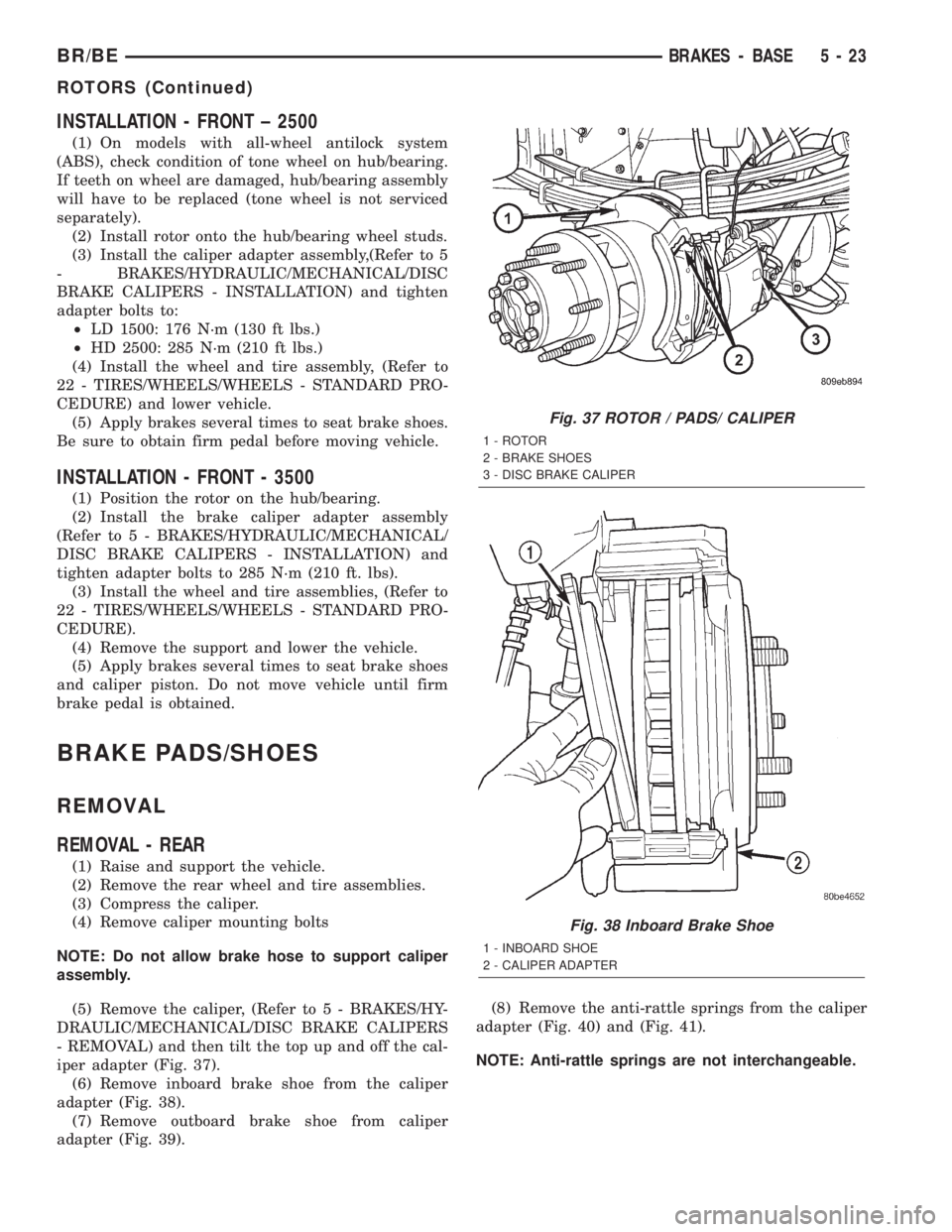
iper adapter (Fig. 37).
(6) Remove inboard brake shoe from the caliper
adapter (Fig. 38).
(7) Remove outboard brake shoe from caliper
adapter (Fig. 39).(8) Remove the anti-rattle springs from the caliper
adapter (Fig. 40) and (Fig. 41).
NOTE: Anti-rattle springs are not interchangeable.
Fig. 37 ROTOR / PADS/ CALIPER
1 - ROTOR
2 - BRAKE SHOES
3 - DISC BRAKE CALIPER
Fig. 38 Inboard Brake Shoe
1 - INBOARD SHOE
2 - CALIPER ADAPTER
BR/BEBRAKES - BASE 5 - 23
ROTORS (Continued)
Page 215 of 2255
(7) Install caliper, (Refer to 5 - BRAKES/HY-
DRAULIC/MECHANICAL/DISC BRAKE CALIPERS
- INSTALLATION) (Refer to 5 - BRAKES/HYDRAU-
LIC/MECHANICAL/DISC BRAKE CALIPERS -
INSTALLATION).
(8) Install wheel and tire assemblies and lower
vehicle, (Refer to 22 - TIRES/WHEELS/WHEELS -
STANDARD PROCEDURE).
(9) Apply brakes several times to seat caliper pis-
tons and brake shoes and obtain firm pedal.
(10) Top off master cylinder fluid level.
INSTALLATION - FRONT
(1) Bottom pistons in caliper bore with C-clamp.
Place an old brake shoe between a C-clamp and cal-
iper piston.
(2) Clean caliper mounting adapter and anti-rattle
springs.
(3) Lubricate anti-rattle springs with Mopar brake
grease.
(4) Install anti-rattle springs.
NOTE: Anti-rattle springs are not interchangeable.
(5) Install inboard brake shoe in adapter.
(6) Install outboard brake shoe in adapter.
(7) Tilt the bottom of the caliper over rotor and
under adapter. Then push the top of the caliper down
onto the adapter.
(8) Install caliper, (Refer to 5 - BRAKES/HY-
DRAULIC/MECHANICAL/DISC BRAKE CALIPERS
- INSTALLATION).
(9) Install wheel and tire assemblies and lower
vehicle, (Refer to 22 - TIRES/WHEELS/WHEELS -
STANDARD PROCEDURE).
(10) Apply brakes several times to seat caliper pis-
tons and brake shoes and obtain firm pedal.
(11) Top off master cylinder fluid level.
MASTER CYLINDER
DESCRIPTION
A two-piece master cylinder is used on all models.
The cylinder body containing the primary and sec-
ondary pistons is made of aluminum. The removable
fluid reservoir is made of nylon reinforced with glass
fiber. The reservoir stores reserve brake fluid for the
hydraulic brake circuits. The reservoir is the only
serviceable component.
The fluid compartments of the nylon reservoir are
interconnected to permit fluid level equalization.
However, the equalization feature does not affect cir-
cuit separation in the event of a front or rear brake
malfunction. The reservoir compartments will retain
enough fluid to operate the functioning hydraulic cir-
cuit.Care must be exercised when removing/installing
the master cylinder connecting lines. The threads in
the cylinder fluid ports can be damaged if care is not
exercised. Start all brake line fittings by hand to
avoid cross threading.
The cylinder reservoir can be replaced when neces-
sary. However, the aluminum body section of the
master cylinder is not a repairable component.
NOTE: If diagnosis indicates that an internal mal-
function has occurred, the aluminum body section
must be replaced as an assembly.
OPERATION
The master cylinder bore contains a primary and
secondary piston. The primary piston supplies
hydraulic pressure to the front brakes. The secondary
piston supplies hydraulic pressure to the rear brakes.
DIAGNOSIS AND TESTING - MASTER
CYLINDER/POWER BOOSTER
(1) Start engine and check booster vacuum hose
connections. A hissing noise indicates vacuum leak.
Correct any vacuum leak before proceeding.
(2) Stop engine and shift transmission into Neu-
tral.
(3) Pump brake pedal until all vacuum reserve in
booster is depleted.
(4) Press and hold brake pedal under light foot
pressure. The pedal should hold firm, if the pedal
falls away master cylinder is faulty (internal leak-
age).
(5) Start engine and note pedal action. It should
fall away slightly under light foot pressure then hold
firm. If no pedal action is discernible, power booster,
vacuum supply, or vacuum check valve is faulty. Pro-
ceed to the POWER BOOSTER VACUUM TEST.
(6) If the POWER BOOSTER VACUUM TEST
passes, rebuild booster vacuum reserve as follows:
Release brake pedal. Increase engine speed to 1500
rpm, close the throttle and immediately turn off igni-
tion to stop engine.
(7) Wait a minimum of 90 seconds and try brake
action again. Booster should provide two or more vac-
uum assisted pedal applications. If vacuum assist is
not provided, booster is faulty.
POWER BOOSTER VACUUM TEST
(1) Connect vacuum gauge to booster check valve
with short length of hose and T-fitting (Fig. 47).
(2) Start and run engine at curb idle speed for one
minute.
(3) Observe the vacuum supply. If vacuum supply
is not adequate, repair vacuum supply.
5 - 26 BRAKES - BASEBR/BE
BRAKE PADS/SHOES (Continued)
Page 297 of 2255
ENGINE COOLANT
THERMOSTAT - 5.9L
DESCRIPTION
CAUTION: Do not operate an engine without a ther-
mostat, except for servicing or testing.
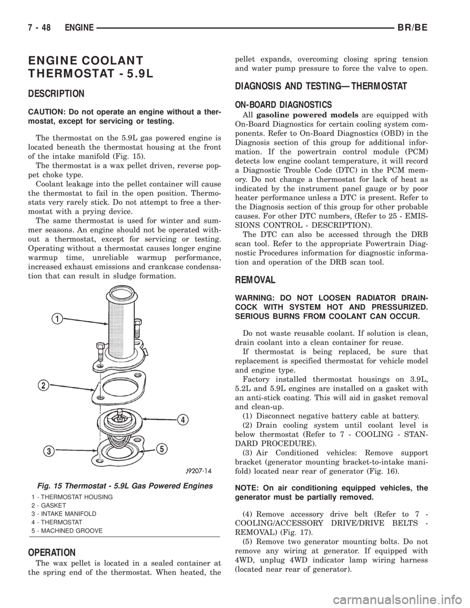
The thermostat on the 5.9L gas powered engine is
located beneath the thermostat housing at the front
of the intake manifold (Fig. 15).
The thermostat is a wax pellet driven, reverse pop-
pet choke type.
Coolant leakage into the pellet container will cause
the thermostat to fail in the open position. Thermo-
stats very rarely stick. Do not attempt to free a ther-
mostat with a prying device.
The same thermostat is used for winter and sum-
mer seasons. An engine should not be operated with-
out a thermostat, except for servicing or testing.
Operating without a thermostat causes longer engine
warmup time, unreliable warmup performance,
increased exhaust emissions and crankcase condensa-
tion that can result in sludge formation.
OPERATION
The wax pellet is located in a sealed container at
the spring end of the thermostat. When heated, thepellet expands, overcoming closing spring tension
and water pump pressure to force the valve to open.
DIAGNOSIS AND TESTINGÐTHERMOSTAT
ON-BOARD DIAGNOSTICS
Allgasoline powered modelsare equipped with
On-Board Diagnostics for certain cooling system com-
ponents. Refer to On-Board Diagnostics (OBD) in the
Diagnosis section of this group for additional infor-
mation. If the powertrain control module (PCM)
detects low engine coolant temperature, it will record
a Diagnostic Trouble Code (DTC) in the PCM mem-
ory. Do not change a thermostat for lack of heat as
indicated by the instrument panel gauge or by poor
heater performance unless a DTC is present. Refer to
the Diagnosis section of this group for other probable
causes. For other DTC numbers, (Refer to 25 - EMIS-
SIONS CONTROL - DESCRIPTION).
The DTC can also be accessed through the DRB
scan tool. Refer to the appropriate Powertrain Diag-
nostic Procedures information for diagnostic informa-
tion and operation of the DRB scan tool.
REMOVAL
WARNING: DO NOT LOOSEN RADIATOR DRAIN-
COCK WITH SYSTEM HOT AND PRESSURIZED.
SERIOUS BURNS FROM COOLANT CAN OCCUR.
Do not waste reusable coolant. If solution is clean,
drain coolant into a clean container for reuse.
If thermostat is being replaced, be sure that
replacement is specified thermostat for vehicle model
and engine type.
Factory installed thermostat housings on 3.9L,
5.2L and 5.9L engines are installed on a gasket with
an anti-stick coating. This will aid in gasket removal
and clean-up.
(1) Disconnect negative battery cable at battery.
(2) Drain cooling system until coolant level is
below thermostat (Refer to 7 - COOLING - STAN-
DARD PROCEDURE).
(3) Air Conditioned vehicles: Remove support
bracket (generator mounting bracket-to-intake mani-
fold) located near rear of generator (Fig. 16).
NOTE: On air conditioning equipped vehicles, the
generator must be partially removed.
(4) Remove accessory drive belt (Refer to 7 -
COOLING/ACCESSORY DRIVE/DRIVE BELTS -
REMOVAL) (Fig. 17).
(5) Remove two generator mounting bolts. Do not
remove any wiring at generator. If equipped with
4WD, unplug 4WD indicator lamp wiring harness
(located near rear of generator).
Fig. 15 Thermostat - 5.9L Gas Powered Engines
1 - THERMOSTAT HOUSING
2 - GASKET
3 - INTAKE MANIFOLD
4 - THERMOSTAT
5 - MACHINED GROOVE
7 - 48 ENGINEBR/BE
Page 300 of 2255
ENGINE COOLANT
THERMOSTAT - 8.0L
DESCRIPTION
CAUTION: Do not operate an engine without a ther-
mostat, except for servicing or testing.
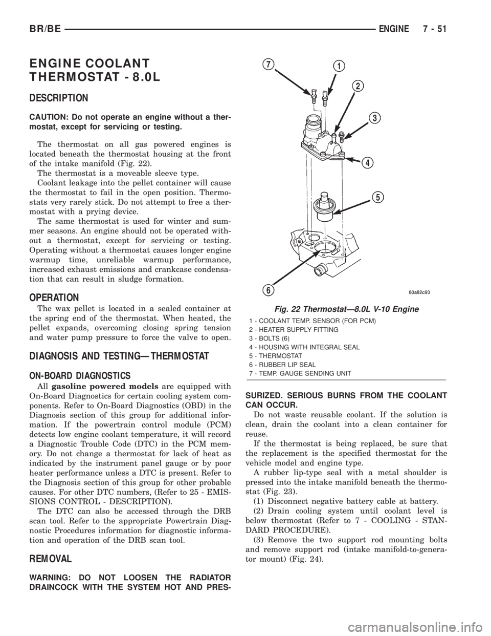
The thermostat on all gas powered engines is
located beneath the thermostat housing at the front
of the intake manifold (Fig. 22).
The thermostat is a moveable sleeve type.
Coolant leakage into the pellet container will cause
the thermostat to fail in the open position. Thermo-
stats very rarely stick. Do not attempt to free a ther-
mostat with a prying device.
The same thermostat is used for winter and sum-
mer seasons. An engine should not be operated with-
out a thermostat, except for servicing or testing.
Operating without a thermostat causes longer engine
warmup time, unreliable warmup performance,
increased exhaust emissions and crankcase condensa-
tion that can result in sludge formation.
OPERATION
The wax pellet is located in a sealed container at
the spring end of the thermostat. When heated, the
pellet expands, overcoming closing spring tension
and water pump pressure to force the valve to open.
DIAGNOSIS AND TESTINGÐTHERMOSTAT
ON-BOARD DIAGNOSTICS
Allgasoline powered modelsare equipped with
On-Board Diagnostics for certain cooling system com-
ponents. Refer to On-Board Diagnostics (OBD) in the
Diagnosis section of this group for additional infor-
mation. If the powertrain control module (PCM)
detects low engine coolant temperature, it will record
a Diagnostic Trouble Code (DTC) in the PCM mem-
ory. Do not change a thermostat for lack of heat as
indicated by the instrument panel gauge or by poor
heater performance unless a DTC is present. Refer to
the Diagnosis section of this group for other probable
causes. For other DTC numbers, (Refer to 25 - EMIS-
SIONS CONTROL - DESCRIPTION).
The DTC can also be accessed through the DRB
scan tool. Refer to the appropriate Powertrain Diag-
nostic Procedures information for diagnostic informa-
tion and operation of the DRB scan tool.
REMOVAL
WARNING: DO NOT LOOSEN THE RADIATOR
DRAINCOCK WITH THE SYSTEM HOT AND PRES-SURIZED. SERIOUS BURNS FROM THE COOLANT
CAN OCCUR.
Do not waste reusable coolant. If the solution is
clean, drain the coolant into a clean container for
reuse.
If the thermostat is being replaced, be sure that
the replacement is the specified thermostat for the
vehicle model and engine type.
A rubber lip-type seal with a metal shoulder is
pressed into the intake manifold beneath the thermo-
stat (Fig. 23).
(1) Disconnect negative battery cable at battery.
(2) Drain cooling system until coolant level is
below thermostat (Refer to 7 - COOLING - STAN-
DARD PROCEDURE).
(3) Remove the two support rod mounting bolts
and remove support rod (intake manifold-to-genera-
tor mount) (Fig. 24).
Fig. 22 ThermostatÐ8.0L V-10 Engine
1 - COOLANT TEMP. SENSOR (FOR PCM)
2 - HEATER SUPPLY FITTING
3 - BOLTS (6)
4 - HOUSING WITH INTEGRAL SEAL
5 - THERMOSTAT
6 - RUBBER LIP SEAL
7 - TEMP. GAUGE SENDING UNIT
BR/BEENGINE 7 - 51
Page 340 of 2255
Audio System Diagnosis
CONDITION POSSIBLE CAUSE CORRECTION
NO DISPLAY 1. Fuse faulty. 1. Check radio fuses in junction block. Replace faulty
fuses, if required.
2. Radio connector faulty. 2. Check for loose or corroded radio connections. Repair,
if required.
3. Wiring faulty. 3. Check for battery voltage at radio connector. Repair
wiring, if required.
4. Ground faulty. 4. Check for continuity between radio chassis and a
known good ground. There should be continuity. Repair
ground, if required.
5. Radio faulty. 5. Refer to Radio in the Diagnosis and Testing section of
this group.
CLOCK WILL NOT KEEP
SET TIME1. Fuse faulty. 1. Check ignition-off draw fuse. Replace faulty fuse, if
required.
2. Radio connector faulty. 2. Check for loose or corroded radio connections. Repair,
if required.
3. Wiring faulty. 3. Check for battery voltage at radio connector. Repair
wiring, if required.
4. Ground faulty. 4. Check for continuity between radio chassis and a
known good ground. There should be continuity. Repair
ground, if required.
5. Radio faulty. 5. Refer to Radio in the Diagnosis and Testing section of
this group.
POOR RADIO
RECEPTION1. Antenna faulty. 1. Refer to Antenna in the Diagnosis and Testing section
of this group.
2. Ground faulty. 2. Check for continuity between radio chassis and a
known good ground. There should be continuity. Repair
ground, if required.
3. Radio faulty. 3. Refer to Radio in the Diagnosis and Testing section of
this group.
4. Faulty EMI or RFI
noise suppression.4. Refer to Radio Frequency Interference in the Diagnosis
and Testing section of this group.
NO/POOR TAPE
OPERATION1. Faulty tape. 1. Insert known good tape and test operation.
2. Foreign objects behind
tape door.2. Remove foreign objects and test operation.
3. Dirty cassette tape
head.3. Clean head with Mopar Cassette Head Cleaner.
4. Faulty tape deck. 4. Exchange or replace radio, if required.
NO COMPACT DISC
OPERATION1. Faulty CD. 1. Insert known good CD and test operation.
2. Foreign material on
CD.2. Clean CD and test operation.
3. Condensation on CD
or optics.3. Allow temperature of vehicle interior to stabilize and
test operation.
4. Faulty CD player. 4. Exchange or replace radio, if required.
BR/BEAUDIO 8A - 3
AUDIO (Continued)
Page 426 of 2255
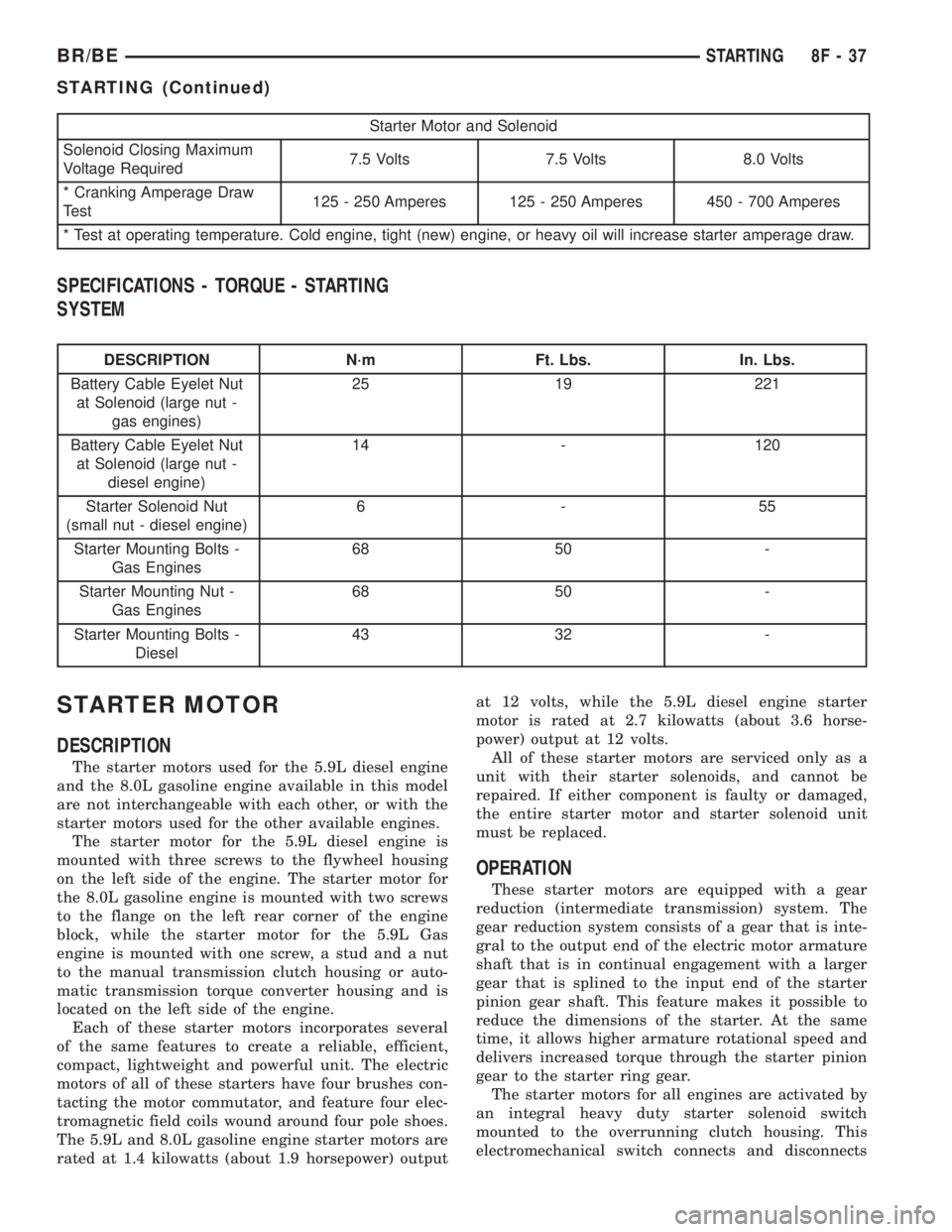
Starter Motor and Solenoid
Solenoid Closing Maximum
Voltage Required7.5 Volts 7.5 Volts 8.0 Volts
* Cranking Amperage Draw
Test125 - 250 Amperes 125 - 250 Amperes 450 - 700 Amperes
* Test at operating temperature. Cold engine, tight (new) engine, or heavy oil will increase starter amperage draw.
SPECIFICATIONS - TORQUE - STARTING
SYSTEM
DESCRIPTION N´m Ft. Lbs. In. Lbs.
Battery Cable Eyelet Nut
at Solenoid (large nut -
gas engines)25 19 221
Battery Cable Eyelet Nut
at Solenoid (large nut -
diesel engine)14 - 120
Starter Solenoid Nut
(small nut - diesel engine)6-55
Starter Mounting Bolts -
Gas Engines68 50 -
Starter Mounting Nut -
Gas Engines68 50 -
Starter Mounting Bolts -
Diesel43 32 -
STARTER MOTOR
DESCRIPTION
The starter motors used for the 5.9L diesel engine
and the 8.0L gasoline engine available in this model
are not interchangeable with each other, or with the
starter motors used for the other available engines.
The starter motor for the 5.9L diesel engine is
mounted with three screws to the flywheel housing
on the left side of the engine. The starter motor for
the 8.0L gasoline engine is mounted with two screws
to the flange on the left rear corner of the engine
block, while the starter motor for the 5.9L Gas
engine is mounted with one screw, a stud and a nut
to the manual transmission clutch housing or auto-
matic transmission torque converter housing and is
located on the left side of the engine.
Each of these starter motors incorporates several
of the same features to create a reliable, efficient,
compact, lightweight and powerful unit. The electric
motors of all of these starters have four brushes con-
tacting the motor commutator, and feature four elec-
tromagnetic field coils wound around four pole shoes.
The 5.9L and 8.0L gasoline engine starter motors are
rated at 1.4 kilowatts (about 1.9 horsepower) outputat 12 volts, while the 5.9L diesel engine starter
motor is rated at 2.7 kilowatts (about 3.6 horse-
power) output at 12 volts.
All of these starter motors are serviced only as a
unit with their starter solenoids, and cannot be
repaired. If either component is faulty or damaged,
the entire starter motor and starter solenoid unit
must be replaced.
OPERATION
These starter motors are equipped with a gear
reduction (intermediate transmission) system. The
gear reduction system consists of a gear that is inte-
gral to the output end of the electric motor armature
shaft that is in continual engagement with a larger
gear that is splined to the input end of the starter
pinion gear shaft. This feature makes it possible to
reduce the dimensions of the starter. At the same
time, it allows higher armature rotational speed and
delivers increased torque through the starter pinion
gear to the starter ring gear.
The starter motors for all engines are activated by
an integral heavy duty starter solenoid switch
mounted to the overrunning clutch housing. This
electromechanical switch connects and disconnects
BR/BESTARTING 8F - 37
STARTING (Continued)
Page 439 of 2255
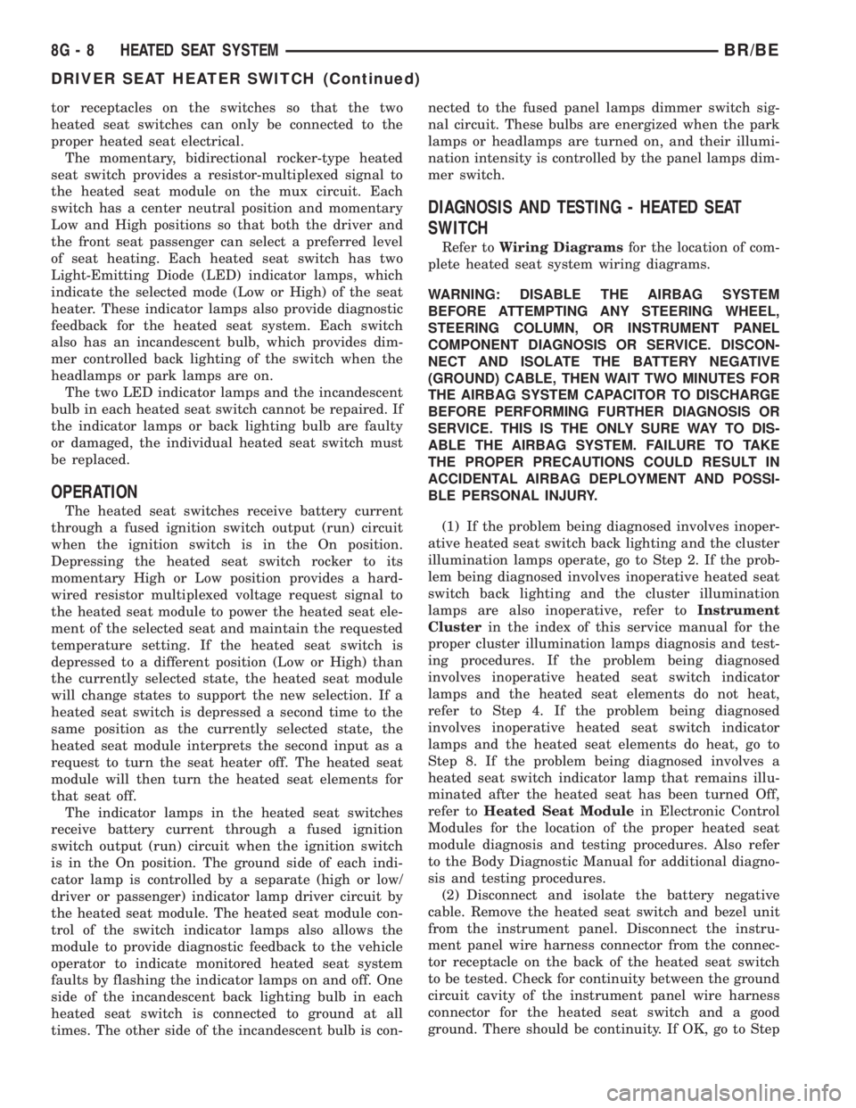
tor receptacles on the switches so that the two
heated seat switches can only be connected to the
proper heated seat electrical.
The momentary, bidirectional rocker-type heated
seat switch provides a resistor-multiplexed signal to
the heated seat module on the mux circuit. Each
switch has a center neutral position and momentary
Low and High positions so that both the driver and
the front seat passenger can select a preferred level
of seat heating. Each heated seat switch has two
Light-Emitting Diode (LED) indicator lamps, which
indicate the selected mode (Low or High) of the seat
heater. These indicator lamps also provide diagnostic
feedback for the heated seat system. Each switch
also has an incandescent bulb, which provides dim-
mer controlled back lighting of the switch when the
headlamps or park lamps are on.
The two LED indicator lamps and the incandescent
bulb in each heated seat switch cannot be repaired. If
the indicator lamps or back lighting bulb are faulty
or damaged, the individual heated seat switch must
be replaced.
OPERATION
The heated seat switches receive battery current
through a fused ignition switch output (run) circuit
when the ignition switch is in the On position.
Depressing the heated seat switch rocker to its
momentary High or Low position provides a hard-
wired resistor multiplexed voltage request signal to
the heated seat module to power the heated seat ele-
ment of the selected seat and maintain the requested
temperature setting. If the heated seat switch is
depressed to a different position (Low or High) than
the currently selected state, the heated seat module
will change states to support the new selection. If a
heated seat switch is depressed a second time to the
same position as the currently selected state, the
heated seat module interprets the second input as a
request to turn the seat heater off. The heated seat
module will then turn the heated seat elements for
that seat off.
The indicator lamps in the heated seat switches
receive battery current through a fused ignition
switch output (run) circuit when the ignition switch
is in the On position. The ground side of each indi-
cator lamp is controlled by a separate (high or low/
driver or passenger) indicator lamp driver circuit by
the heated seat module. The heated seat module con-
trol of the switch indicator lamps also allows the
module to provide diagnostic feedback to the vehicle
operator to indicate monitored heated seat system
faults by flashing the indicator lamps on and off. One
side of the incandescent back lighting bulb in each
heated seat switch is connected to ground at all
times. The other side of the incandescent bulb is con-nected to the fused panel lamps dimmer switch sig-
nal circuit. These bulbs are energized when the park
lamps or headlamps are turned on, and their illumi-
nation intensity is controlled by the panel lamps dim-
mer switch.
DIAGNOSIS AND TESTING - HEATED SEAT
SWITCH
Refer toWiring Diagramsfor the location of com-
plete heated seat system wiring diagrams.
WARNING: DISABLE THE AIRBAG SYSTEM
BEFORE ATTEMPTING ANY STEERING WHEEL,
STEERING COLUMN, OR INSTRUMENT PANEL
COMPONENT DIAGNOSIS OR SERVICE. DISCON-
NECT AND ISOLATE THE BATTERY NEGATIVE
(GROUND) CABLE, THEN WAIT TWO MINUTES FOR
THE AIRBAG SYSTEM CAPACITOR TO DISCHARGE
BEFORE PERFORMING FURTHER DIAGNOSIS OR
SERVICE. THIS IS THE ONLY SURE WAY TO DIS-
ABLE THE AIRBAG SYSTEM. FAILURE TO TAKE
THE PROPER PRECAUTIONS COULD RESULT IN
ACCIDENTAL AIRBAG DEPLOYMENT AND POSSI-
BLE PERSONAL INJURY.
(1) If the problem being diagnosed involves inoper-
ative heated seat switch back lighting and the cluster
illumination lamps operate, go to Step 2. If the prob-
lem being diagnosed involves inoperative heated seat
switch back lighting and the cluster illumination
lamps are also inoperative, refer toInstrument
Clusterin the index of this service manual for the
proper cluster illumination lamps diagnosis and test-
ing procedures. If the problem being diagnosed
involves inoperative heated seat switch indicator
lamps and the heated seat elements do not heat,
refer to Step 4. If the problem being diagnosed
involves inoperative heated seat switch indicator
lamps and the heated seat elements do heat, go to
Step 8. If the problem being diagnosed involves a
heated seat switch indicator lamp that remains illu-
minated after the heated seat has been turned Off,
refer toHeated Seat Modulein Electronic Control
Modules for the location of the proper heated seat
module diagnosis and testing procedures. Also refer
to the Body Diagnostic Manual for additional diagno-
sis and testing procedures.
(2) Disconnect and isolate the battery negative
cable. Remove the heated seat switch and bezel unit
from the instrument panel. Disconnect the instru-
ment panel wire harness connector from the connec-
tor receptacle on the back of the heated seat switch
to be tested. Check for continuity between the ground
circuit cavity of the instrument panel wire harness
connector for the heated seat switch and a good
ground. There should be continuity. If OK, go to Step
8G - 8 HEATED SEAT SYSTEMBR/BE
DRIVER SEAT HEATER SWITCH (Continued)