gas type DODGE RAM 2002 Service Repair Manual
[x] Cancel search | Manufacturer: DODGE, Model Year: 2002, Model line: RAM, Model: DODGE RAM 2002Pages: 2255, PDF Size: 62.07 MB
Page 15 of 2255
FLUID TYPES
DESCRIPTION - FUEL REQUIREMENTS - GAS
ENGINES
Your engine is designed to meet all emissions reg-
ulations and provide excellent fuel economy and per-
formance when using high quality unleaded gasoline
having an octane rating of 87. The use of premium
gasoline is not recommended. The use of premium
gasoline will provide no benefit over high quality reg-
ular gasoline, and in some circumstances may result
in poorer performance.
Light spark knock at low engine speeds is not
harmful to your engine. However, continued heavy
spark knock at high speeds can cause damage and
immediate service is required. Engine damage result-
ing from operation with a heavy spark knock may
not be covered by the new vehicle warranty.
Poor quality gasoline can cause problems such as
hard starting, stalling and hesitations. If you experi-
ence these symptoms, try another brand of gasoline
before considering service for the vehicle.
Over 40 auto manufacturers world-wide have
issued and endorsed consistent gasoline specifications
(the Worldwide Fuel Charter, WWFC) to define fuel
properties necessary to deliver enhanced emissions,
performance and durability for your vehicle. We rec-
ommend the use of gasolines that meet the WWFC
specifications if they are available.
REFORMULATED GASOLINE
Many areas of the country require the use of
cleaner burning gasoline referred to as ªreformulat-
edº gasoline. Reformulated gasoline contain oxygen-
ates, and are specifically blended to reduce vehicle
emissions and improve air quality.
We strongly supports the use of reformulated gas-
oline. Properly blended reformulated gasoline will
provide excellent performance and durability for the
engine and fuel system components.
GASOLINE/OXYGENATE BLENDS
Some fuel suppliers blend unleaded gasoline with
oxygenates such as 10% ethanol, MTBE, and ETBE.
Oxygenates are required in some areas of the country
during the winter months to reduce carbon monoxide
emissions. Fuels blended with these oxygenates may
be used in your vehicle.
CAUTION: DO NOT use gasoline containing METH-
ANOL. Gasoline containing methanol may damage
critical fuel system components.
MMT IN GASOLINE
MMT is a manganese-containing metallic additive
that is blended into some gasoline to increase octane.
Gasoline blended with MMT provide no performance
advantage beyond gasoline of the same octane num-
ber without MMT. Gasoline blended with MMT
reduce spark plug life and reduce emission system
performance in some vehicles. We recommend that
gasolines free of MMT be used in your vehicle. The
MMT content of gasoline may not be indicated on the
gasoline pump; therefore, you should ask your gaso-
line retailer whether or not his/her gasoline contains
MMT.
It is even more important to look for gasoline with-
out MMT in Canada because MMT can be used at
levels higher than allowed in the United States.
MMT is prohibited in Federal and California refor-
mulated gasoline.
SULFUR IN GASOLINE
If you live in the northeast United States, your
vehicle may have been designed to meet California
low emission standards with Cleaner-Burning Cali-
fornia reformulated gasoline with low sulfur. If such
fuels are not available in states adopting California
emission standards, your vehicles will operate satis-
factorily on fuels meeting federal specifications, but
emission control system performance may be
adversely affected. Gasoline sold outside of California
is permitted to have higher sulfur levels which may
affect the performance of the vehicle's catalytic con-
verter. This may cause the Malfunction Indicator
Lamp (MIL), Check Engine or Service Engine Soon
light to illuminate. We recommend that you try a dif-
ferent brand of unleaded gasoline having lower sulfur
to determine if the problem is fuel related prior to
returning your vehicle to an authorized dealer for
service.
CAUTION: If the Malfunction Indicator Lamp (MIL),
Check Engine or Service Engine Soon light is flash-
ing, immediate service is required; see on-board
diagnostics system section.
MATERIALS ADDED TO FUEL
All gasoline sold in the United States and Canada
are required to contain effective detergent additives.
Use of additional detergents or other additives is not
needed under normal conditions.
FUEL SYSTEM CAUTIONS
CAUTION: Follow these guidelines to maintain your
vehicle's performance:
0 - 2 LUBRICATION & MAINTENANCEBR/BE
Page 16 of 2255
²The use of leaded gas is prohibited by Federal
law. Using leaded gasoline can impair engine perfor-
mance, damage the emission control system, and
could result in loss of warranty coverage.
²An out-of-tune engine, or certain fuel or ignition
malfunctions, can cause the catalytic converter to
overheat. If you notice a pungent burning odor or
some light smoke, your engine may be out of tune or
malfunctioning and may require immediate service.
Contact your dealer for service assistance.
²When pulling a heavy load or driving a fully
loaded vehicle when the humidity is low and the tem-
perature is high, use a premium unleaded fuel to
help prevent spark knock. If spark knock persists,
lighten the load, or engine piston damage may result.
²The use of fuel additives which are now being
sold as octane enhancers is not recommended. Most
of these products contain high concentrations of
methanol. Fuel system damage or vehicle perfor-
mance problems resulting from the use of such fuels
or additives is not the responsibility of
DaimlerChrysler Corporation and may not be covered
under the new vehicle warranty.
NOTE: Intentional tampering with emissions control
systems can result in civil penalties being assessed
against you.
DESCRIPTION - FUEL REQUIREMENTS -
DIESEL ENGINE
DESCRIPTION
WARNING: Do not use alcohol or gasoline as a fuel
blending agent. They can be unstable under certain
conditions and hazardous or explosive when mixed
with diesel fuel.
Use good quality diesel fuel from a reputable sup-
plier in your Dodge truck. For most year-round ser-
vice, number 2 diesel fuel meeting ASTM
specification D-975 will provide good performance. If
the vehicle is exposed to extreme cold (below 0ÉF/-
18ÉC), or is required to operate at colder-than-normal
conditions for prolonged periods, use climatized No. 2
diesel fuel or dilute the No. 2 diesel fuel with 50%
No. 1 diesel fuel. This will provide better protection
from fuel gelling or wax-plugging of the fuel filters.
Diesel fuel is seldom completely free of water. To
prevent fuel system trouble, including fuel line freez-
ing in winter, drain the accumulated water from the
fuel/water separator using the fuel/water separator
drain provided. If you buy good-quality fuel and fol-
low the cold-weather advice above, fuel conditioners
should not be required in your vehicle. If available in
your area, a high cetane ªpremiumº diesel fuel mayoffer improved cold starting and warm-up perfor-
mance.
DESCRIPTION - ENGINE COOLANT
WARNING: ANTIFREEZE IS AN ETHYLENE GLYCOL
BASE COOLANT AND IS HARMFUL IF SWAL-
LOWED OR INHALED. IF SWALLOWED, DRINK
TWO GLASSES OF WATER AND INDUCE VOMIT-
ING. IF INHALED, MOVE TO FRESH AIR AREA.
SEEK MEDICAL ATTENTION IMMEDIATELY. DO NOT
STORE IN OPEN OR UNMARKED CONTAINERS.
WASH SKIN AND CLOTHING THOROUGHLY AFTER
COMING IN CONTACT WITH ETHYLENE GLYCOL.
KEEP OUT OF REACH OF CHILDREN. DISPOSE OF
GLYCOL BASE COOLANT PROPERLY, CONTACT
YOUR DEALER OR GOVERNMENT AGENCY FOR
LOCATION OF COLLECTION CENTER IN YOUR
AREA. DO NOT OPEN A COOLING SYSTEM WHEN
THE ENGINE IS AT OPERATING TEMPERATURE OR
HOT UNDER PRESSURE, PERSONAL INJURY CAN
RESULT. AVOID RADIATOR COOLING FAN WHEN
ENGINE COMPARTMENT RELATED SERVICE IS
PERFORMED, PERSONAL INJURY CAN RESULT.
CAUTION: Use of Propylene Glycol based coolants
is not recommended, as they provide less freeze
protection and less corrosion protection.
The cooling system is designed around the coolant.
The coolant must accept heat from engine metal, in
the cylinder head area near the exhaust valves and
engine block. Then coolant carries the heat to the
radiator where the tube/fin radiator can transfer the
heat to the air.
The use of aluminum cylinder blocks, cylinder
heads, and water pumps requires special corrosion
protection. MopartAntifreeze/Coolant, 5
Year/100,000 Mile Formula (MS-9769), or the equiva-
lent ethylene glycol base coolant with organic corro-
sion inhibitors (called HOAT, for Hybrid Organic
Additive Technology) is recommended. This coolant
offers the best engine cooling without corrosion when
mixed with 50% Ethylene Glycol and 50% distilled
water to obtain a freeze point of -37ÉC (-35ÉF). If it
loses color or becomes contaminated, drain, flush,
and replace with fresh properly mixed coolant solu-
tion.
CAUTION: MoparTAntifreeze/Coolant, 5
Year/100,000 Mile Formula (MS-9769) may not be
mixed with any other type of antifreeze. Mixing of
coolants other than specified (non-HOAT or other
HOAT), may result in engine damage that may not
be covered under the new vehicle warranty, and
decreased corrosion protection.
BR/BELUBRICATION & MAINTENANCE 0 - 3
FLUID TYPES (Continued)
Page 17 of 2255
COOLANT PERFORMANCE
The required ethylene-glycol (antifreeze) and water
mixture depends upon climate and vehicle operating
conditions. The coolant performance of various mix-
tures follows:
Pure Water-Water can absorb more heat than a
mixture of water and ethylene-glycol. This is for pur-
pose of heat transfer only. Water also freezes at a
higher temperature and allows corrosion.
100 percent Ethylene-Glycol-The corrosion
inhibiting additives in ethylene-glycol need the pres-
ence of water to dissolve. Without water, additives
form deposits in system. These act as insulation
causing temperature to rise to as high as 149ÉC
(300ÉF). This temperature is hot enough to melt plas-
tic and soften solder. The increased temperature can
result in engine detonation. In addition, 100 percent
ethylene-glycol freezes at -22ÉC (-8ÉF).
50/50 Ethylene-Glycol and Water-Is the recom-
mended mixture, it provides protection against freez-
ing to -37ÉC (-34ÉF). The antifreeze concentration
must alwaysbe a minimum of 44 percent, year-
round in all climates. If percentage is lower, engine
parts may be eroded by cavitation. Maximum protec-
tion against freezing is provided with a 68 percent
antifreeze concentration, which prevents freezing
down to -67.7ÉC (-90ÉF). A higher percentage will
freeze at a warmer temperature. Also, a higher per-
centage of antifreeze can cause the engine to over-
heat because specific heat of antifreeze is lower than
that of water.
CAUTION: Richer antifreeze mixtures cannot be
measured with normal field equipment and can
cause problems associated with 100 percent ethyl-
ene-glycol.
COOLANT SELECTION AND ADDITIVES
NOTE: Refer to the vehicle's coolant bottle to iden-
tify HOAT or Non-HOAT coolant. Non-HOAT coolant
is green in color.
The use of aluminum cylinder blocks, cylinder
heads and water pumps requires special corrosion
protection. Only MopartAntifreeze/Coolant, 5
Year/100,000 Mile Formula (glycol base coolant with
corrosion inhibitors called HOAT, for Hybrid Organic
Additive Technology) is recommended. This coolant
offers the best engine cooling without corrosion when
mixed with 50% distilled water to obtain to obtain a
freeze point of -37ÉC (-35ÉF). If it loses color or
becomes contaminated, drain, flush, and replace with
fresh properly mixed coolant solution.CAUTION: Do not use coolant additives that are
claimed to improve engine cooling.
DESCRIPTIONÐENGINE OIL
API SERVICE GRADE CERTIFIED
WARNING: NEW OR USED ENGINE OIL CAN BE
IRRITATING TO THE SKIN. AVOID PROLONGED OR
REPEATED SKIN CONTACT WITH ENGINE OIL.
CONTAMINANTS IN USED ENGINE OIL, CAUSED BY
INTERNAL COMBUSTION, CAN BE HAZARDOUS TO
YOUR HEALTH. THOROUGHLY WASH EXPOSED
SKIN WITH SOAP AND WATER. DO NOT WASH
SKIN WITH GASOLINE, DIESEL FUEL, THINNER, OR
SOLVENTS, HEALTH PROBLEMS CAN RESULT. DO
NOT POLLUTE, DISPOSE OF USED ENGINE OIL
PROPERLY. CONTACT YOUR DEALER OR GOVERN-
MENT AGENCY FOR LOCATION OF COLLECTION
CENTER IN YOUR AREA.
Standard engine-oil identification notations have
been adopted to aid in the proper selection of engine
oil. The identifying notations are located on the label
of engine oil plastic bottles and the top of engine oil
cans.
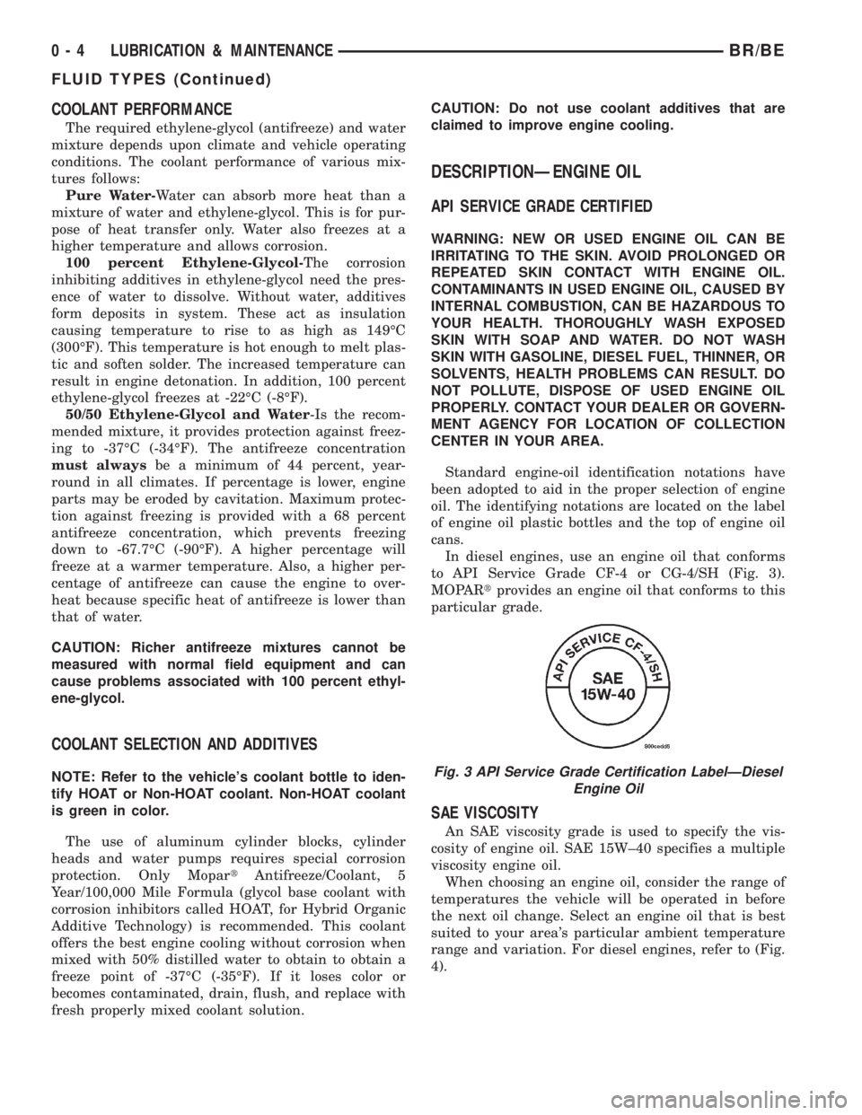
In diesel engines, use an engine oil that conforms
to API Service Grade CF-4 or CG-4/SH (Fig. 3).
MOPARtprovides an engine oil that conforms to this
particular grade.
SAE VISCOSITY
An SAE viscosity grade is used to specify the vis-
cosity of engine oil. SAE 15W±40 specifies a multiple
viscosity engine oil.
When choosing an engine oil, consider the range of
temperatures the vehicle will be operated in before
the next oil change. Select an engine oil that is best
suited to your area's particular ambient temperature
range and variation. For diesel engines, refer to (Fig.
4).
Fig. 3 API Service Grade Certification LabelÐDiesel
Engine Oil
0 - 4 LUBRICATION & MAINTENANCEBR/BE
FLUID TYPES (Continued)
Page 18 of 2255
DESCRIPTION - ENGINE OIL
WARNING: NEW OR USED ENGINE OIL CAN BE
IRRITATING TO THE SKIN. AVOID PROLONGED OR
REPEATED SKIN CONTACT WITH ENGINE OIL.
CONTAMINANTS IN USED ENGINE OIL, CAUSED BY
INTERNAL COMBUSTION, CAN BE HAZARDOUS TO
YOUR HEALTH. THOROUGHLY WASH EXPOSED
SKIN WITH SOAP AND WATER. DO NOT WASH
SKIN WITH GASOLINE, DIESEL FUEL, THINNER, OR
SOLVENTS, HEALTH PROBLEMS CAN RESULT. DO
NOT POLLUTE, DISPOSE OF USED ENGINE OIL
PROPERLY. CONTACT YOUR DEALER OR GOVERN-
MENT AGENCY FOR LOCATION OF COLLECTION
CENTER IN YOUR AREA.
API SERVICE GRADE CERTIFIED
Use an engine oil that is API Service Grade Certi-
fied. MOPARtprovides engine oils that conform to
this service grade.
SAE VISCOSITY
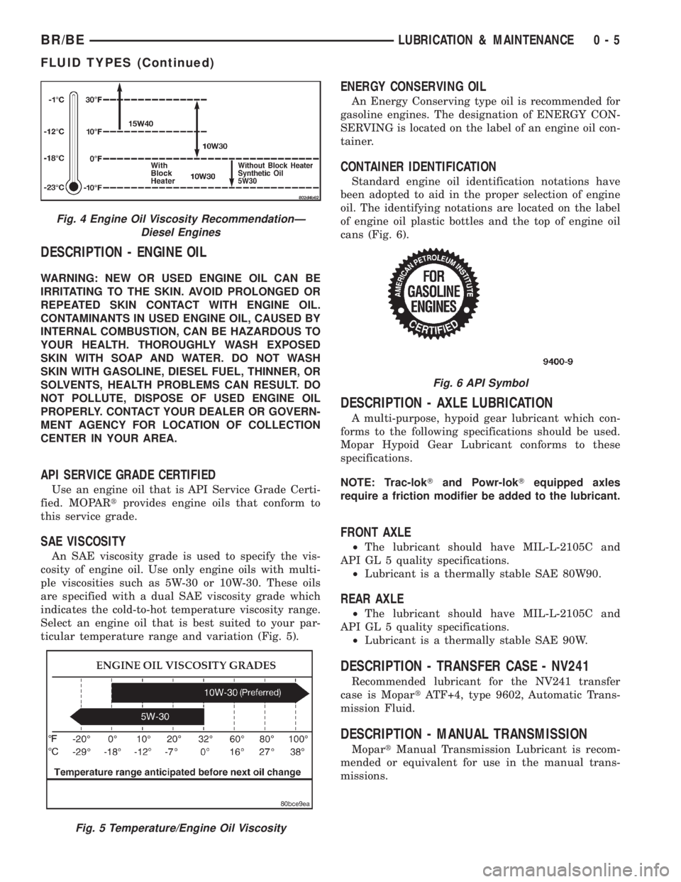
An SAE viscosity grade is used to specify the vis-
cosity of engine oil. Use only engine oils with multi-
ple viscosities such as 5W-30 or 10W-30. These oils
are specified with a dual SAE viscosity grade which
indicates the cold-to-hot temperature viscosity range.
Select an engine oil that is best suited to your par-
ticular temperature range and variation (Fig. 5).
ENERGY CONSERVING OIL
An Energy Conserving type oil is recommended for
gasoline engines. The designation of ENERGY CON-
SERVING is located on the label of an engine oil con-
tainer.
CONTAINER IDENTIFICATION
Standard engine oil identification notations have
been adopted to aid in the proper selection of engine
oil. The identifying notations are located on the label
of engine oil plastic bottles and the top of engine oil
cans (Fig. 6).
DESCRIPTION - AXLE LUBRICATION
A multi-purpose, hypoid gear lubricant which con-
forms to the following specifications should be used.
Mopar Hypoid Gear Lubricant conforms to these
specifications.
NOTE: Trac-lokTand Powr-lokTequipped axles
require a friction modifier be added to the lubricant.
FRONT AXLE
²The lubricant should have MIL-L-2105C and
API GL 5 quality specifications.
²Lubricant is a thermally stable SAE 80W90.
REAR AXLE
²The lubricant should have MIL-L-2105C and
API GL 5 quality specifications.
²Lubricant is a thermally stable SAE 90W.
DESCRIPTION - TRANSFER CASE - NV241
Recommended lubricant for the NV241 transfer
case is MopartATF+4, type 9602, Automatic Trans-
mission Fluid.
DESCRIPTION - MANUAL TRANSMISSION
MopartManual Transmission Lubricant is recom-
mended or equivalent for use in the manual trans-
missions.
Fig. 4 Engine Oil Viscosity RecommendationÐ
Diesel Engines
Fig. 5 Temperature/Engine Oil Viscosity
Fig. 6 API Symbol
BR/BELUBRICATION & MAINTENANCE 0 - 5
FLUID TYPES (Continued)
Page 178 of 2255
AXLE SHAFTS
REMOVAL
(1) Remove the axle shaft flange bolts.
(2) Slide the axle shaft out from the axle tube.
INSTALLATION
(1) Clean the gasket contact surface area on the
flange with an appropriate solvent. Install a new
flange gasket and slide the axle shaft into the tube.
(2) Install the bolts and tighten to 129 N´m (95 ft.
lbs.).
AXLE BEARINGS
REMOVAL
(1) Remove wheel and tire assembly.
(2) Remove brake drum.
(3) Remove the axle shaft.
(4) Remove the lock wedge and adjustment nut.
Remove adjustment nut with Socket DD-1241-JD.
(5) Remove the hub assembly. The outer axle bear-
ing will slide out as the hub is being removed.
(6) Drive grease seal and inner bearing out of the
hub with Installer 5064 and Handle C-4171.
(7) Remove bearing cups from the hub with a
brass drift and a hammer.
INSTALLATION
(1) Thoroughly clean both axle bearings and inte-
rior of the hub with an appropriate cleaning solvent.
(2) Install bearing cups with Installer 8153 and
Handle C-4171.
(3) Pack inner and outer bearings with Mopar
wheel bearing grease or equivalent
(4) Apply lubricant to surface area of the bearing
cup.
(5) Install inner axle bearing in the hub.
(6) Install anewbearing grease seal with
Installer 8152 and Handle C-4171.
(7) Inspect bearing and seal contact surfaces on
the axle tube spindle for burrs and/or roughness.
Remove all the rough contact surfaces from the axle
spindle.
CAUTION: Do not let grease seal contact the axle
tube threads during installation.
(8) Carefully slide the hub onto the axle.
(9) Install outer axle bearing.
(10) Install hub bearing adjustment nut with
Socket DD-1241±JD.
(11) Tighten adjustment nut to 163-190 N´m (120-
140 ft. lbs.) while rotating the wheel.(12) Loosen adjustment nut 1/8 of-a-turn to pro-
vide 0.001-inch to 0.010-inch wheel bearing end play.
(13) Tap the locking wedge into the spindle key-
way and adjustment nut.
NOTE: Locate locking wedge in a new position in
the adjustment nut.
(14) Install axle shaft and brake drum.
(15) Install wheel and tire assembly.
PINION SEAL
REMOVAL
(1) Raise and support the vehicle.
(2) Mark the universal joint, pinion yoke, and pin-
ion shaft for installation reference.
(3) Disconnect the propeller shaft from the pinion
yoke. Secure the propeller shaft in an upright posi-
tion to prevent damage to the rear universal joint.
(4) Remove wheel and tire assemblies.
(5) Remove brake calipers to prevent any drag.
The drag may cause a false bearing preload torque
measurement.
(6) Rotate pinion yoke three or four times.
(7) Record the amount of torque necessary to
rotate the pinion gear with an inch pound dial-type
torque wrench.
(8) Hold the yoke with Holder 6719A and remove
the pinion shaft nut and washer.
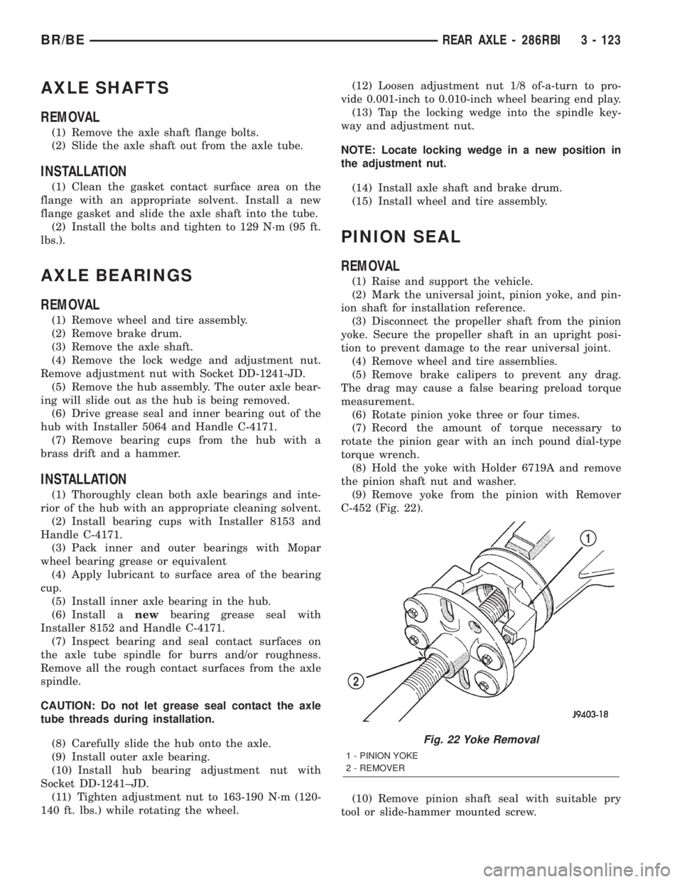
(9) Remove yoke from the pinion with Remover
C-452 (Fig. 22).
(10) Remove pinion shaft seal with suitable pry
tool or slide-hammer mounted screw.
Fig. 22 Yoke Removal
1 - PINION YOKE
2 - REMOVER
BR/BEREAR AXLE - 286RBI 3 - 123
Page 191 of 2255
BRAKE PADS/SHOES
REMOVAL
REMOVAL - REAR.....................23
REMOVAL - FRONT....................24
INSTALLATION
INSTALLATION - REAR.................25
INSTALLATION - FRONT................26
MASTER CYLINDER
DESCRIPTION.........................26
OPERATION...........................26
DIAGNOSIS AND TESTING - MASTER
CYLINDER/POWER BOOSTER...........26
STANDARD PROCEDURE - MASTER
CYLINDER BLEEDING..................27
REMOVAL.............................27
INSTALLATION.........................28
PARKING BRAKE
DESCRIPTION.........................28
OPERATION...........................28
PEDAL
REMOVAL.............................28
INSTALLATION.........................29CABLES
REMOVAL
REMOVAL - REAR PARK BRAKE CABLE . . . 29
REMOVAL - FRONT PARKING BRAKE
CABLE..............................29
INSTALLATION
INSTALLATION - REAR PARK BRAKE
CABLE..............................30
INSTALLATION - FRONT PARKING BRAKE
CABLE..............................30
CABLE TENSIONER
ADJUSTMENTS
ADJUSTMENT........................30
RELEASE HANDLE
REMOVAL.............................31
INSTALLATION.........................32
SHOES
REMOVAL.............................32
INSTALLATION.........................32
ADJUSTMENTS
ADJUSTMENT - PARKING BRAKE SHOES . . 33
BRAKES - BASE
SPECIFICATIONS
BASE BRAKE
SPECIFICATIONS
DESCRIPTION SPECIFICATION
Front/Rear Disc Brake
Caliper
TypeDual Piston Sliding
Front Disc Brake Caliper
Piston Diameter HD56 mm (2.00 in.)
Front Disc Brake Rotor 326.5ý36 mm
(12.5ý1.5 in.)
Front/Rear Disc Brake
Rotor
Max. Runout0.127 mm (0.005 in.)
Front/Rear Disc Brake
Rotor
Max. Thickness Variation0.025 mm (0.001 in.)
DESCRIPTION SPECIFICATION
Minimum Front Rotor
Thickness33.90 mm (1.334 in.)
Mininium Rear Rotor
Thickness28.39 mm (1.117 in)
Rear Disc Brake Caliper
25002x45 mm (1.77 in)
Rear Disc Brake Caliper
35002x51 mm (2.00 in)
Rear Disc Brake Rotor
2500/3500323.5x30 mm (1.18 in)
Brake Booster
Type
2500 Gasoline EnginesVacuum Dual Diaphragm
Brake Booster
Type
All 3500/
2500 Diesel Engines
OnlyHydraulic
5 - 2 BRAKES - BASEBR/BE
Page 258 of 2255
CONDITION POSSIBLE CAUSES CORRECTION
8. Incorrect coolant concentration 8. Check coolant. (Refer to
LUBRICATION & MAINTENANCE/
FLUID TYPES - DESCRIPTION).
9. Coolant not flowing through
system9. Check for coolant flow at radiator
filler neck with some coolant
removed, engine warm and
thermostat open. Coolant should be
observed flowing through radiator. If
flow is not observed, determine area
of obstruction and repair as
necessary.
10. Radiator or A/C condenser fins
are dirty or clogged.10. Remove insects and debris.
(Refer to 7 - COOLING -
STANDARD PROCEDURE).
11. Radiator core is corroded or
plugged.11. Have radiator re-cored or
replaced.
12. Aftermarket A/C installed
without proper radiator.12. Install proper radiator.
13. Fuel or ignition system
problems.13. Refer to 14 - Fuel System or 8 -
Electrical for diagnosis and testing
procedures.
14. Dragging brakes. 14. Check and correct as
necessary. (Refer to 5 - BRAKES -
DIAGNOSIS AND TESTING) for
correct procedures.
15. Bug screen or cardboard is
being used, reducing airflow.15. Remove bug screen or
cardboard.
16. Thermostat partially or
completely shut.16. Check thermostat operation and
replace as necessary. (Refer to 7 -
COOLING/ENGINE/ENGINE
COOLANT THERMOSTAT -
REMOVAL).
17. Viscous fan drive not operating
properly.17. Check fan drive operation and
replace as necessary. (Refer to 7 -
COOLING/ENGINE/FAN DRIVE
VISCOUS CLUTCH - REMOVAL).
18. Cylinder head gasket leaking. 18. Check for cylinder head gasket
leaks. (Refer to 7 - COOLING -
DIAGNOSIS AND TESTING).
19. Heater core leaking. 19. Check heater core for leaks.
(Refer to 24 - HEATING & AIR
CONDITIONING/PLUMBING -
DIAGNOSIS AND TESTING).
Repair as necessary.
BR/BECOOLING 7 - 9
COOLING (Continued)
Page 297 of 2255
ENGINE COOLANT
THERMOSTAT - 5.9L
DESCRIPTION
CAUTION: Do not operate an engine without a ther-
mostat, except for servicing or testing.
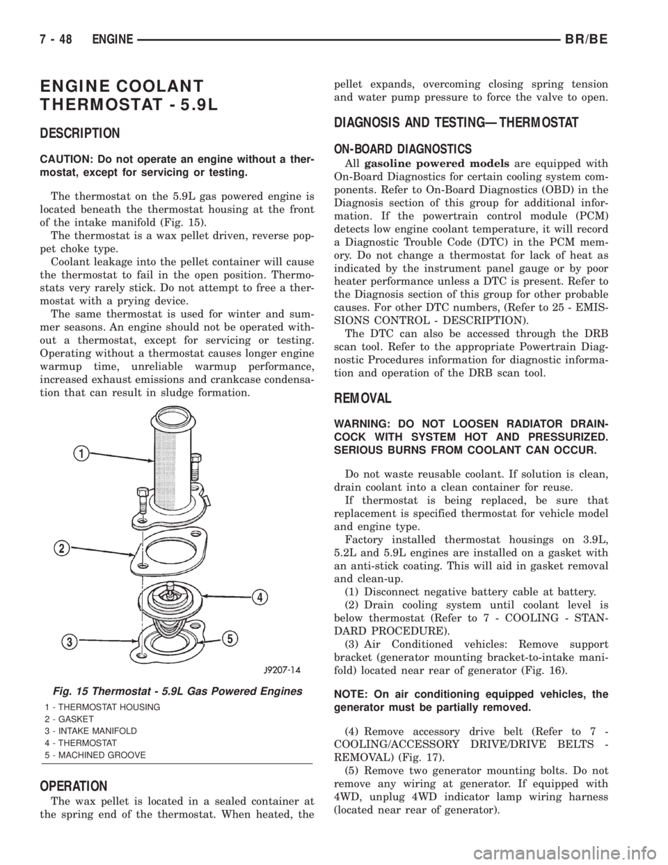
The thermostat on the 5.9L gas powered engine is
located beneath the thermostat housing at the front
of the intake manifold (Fig. 15).
The thermostat is a wax pellet driven, reverse pop-
pet choke type.
Coolant leakage into the pellet container will cause
the thermostat to fail in the open position. Thermo-
stats very rarely stick. Do not attempt to free a ther-
mostat with a prying device.
The same thermostat is used for winter and sum-
mer seasons. An engine should not be operated with-
out a thermostat, except for servicing or testing.
Operating without a thermostat causes longer engine
warmup time, unreliable warmup performance,
increased exhaust emissions and crankcase condensa-
tion that can result in sludge formation.
OPERATION
The wax pellet is located in a sealed container at
the spring end of the thermostat. When heated, thepellet expands, overcoming closing spring tension
and water pump pressure to force the valve to open.
DIAGNOSIS AND TESTINGÐTHERMOSTAT
ON-BOARD DIAGNOSTICS
Allgasoline powered modelsare equipped with
On-Board Diagnostics for certain cooling system com-
ponents. Refer to On-Board Diagnostics (OBD) in the
Diagnosis section of this group for additional infor-
mation. If the powertrain control module (PCM)
detects low engine coolant temperature, it will record
a Diagnostic Trouble Code (DTC) in the PCM mem-
ory. Do not change a thermostat for lack of heat as
indicated by the instrument panel gauge or by poor
heater performance unless a DTC is present. Refer to
the Diagnosis section of this group for other probable
causes. For other DTC numbers, (Refer to 25 - EMIS-
SIONS CONTROL - DESCRIPTION).
The DTC can also be accessed through the DRB
scan tool. Refer to the appropriate Powertrain Diag-
nostic Procedures information for diagnostic informa-
tion and operation of the DRB scan tool.
REMOVAL
WARNING: DO NOT LOOSEN RADIATOR DRAIN-
COCK WITH SYSTEM HOT AND PRESSURIZED.
SERIOUS BURNS FROM COOLANT CAN OCCUR.
Do not waste reusable coolant. If solution is clean,
drain coolant into a clean container for reuse.
If thermostat is being replaced, be sure that
replacement is specified thermostat for vehicle model
and engine type.
Factory installed thermostat housings on 3.9L,
5.2L and 5.9L engines are installed on a gasket with
an anti-stick coating. This will aid in gasket removal
and clean-up.
(1) Disconnect negative battery cable at battery.
(2) Drain cooling system until coolant level is
below thermostat (Refer to 7 - COOLING - STAN-
DARD PROCEDURE).
(3) Air Conditioned vehicles: Remove support
bracket (generator mounting bracket-to-intake mani-
fold) located near rear of generator (Fig. 16).
NOTE: On air conditioning equipped vehicles, the
generator must be partially removed.
(4) Remove accessory drive belt (Refer to 7 -
COOLING/ACCESSORY DRIVE/DRIVE BELTS -
REMOVAL) (Fig. 17).
(5) Remove two generator mounting bolts. Do not
remove any wiring at generator. If equipped with
4WD, unplug 4WD indicator lamp wiring harness
(located near rear of generator).
Fig. 15 Thermostat - 5.9L Gas Powered Engines
1 - THERMOSTAT HOUSING
2 - GASKET
3 - INTAKE MANIFOLD
4 - THERMOSTAT
5 - MACHINED GROOVE
7 - 48 ENGINEBR/BE
Page 298 of 2255
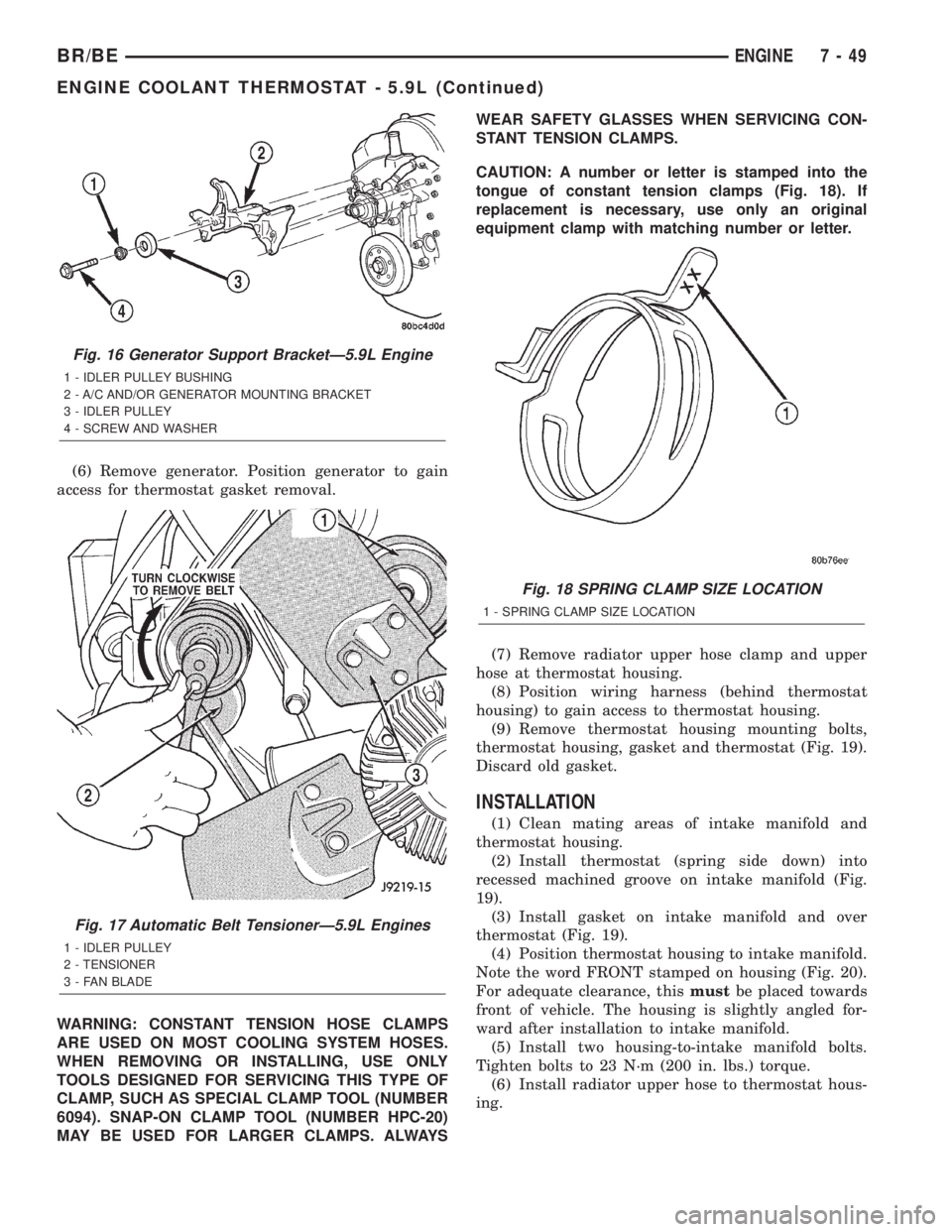
(6) Remove generator. Position generator to gain
access for thermostat gasket removal.
WARNING: CONSTANT TENSION HOSE CLAMPS
ARE USED ON MOST COOLING SYSTEM HOSES.
WHEN REMOVING OR INSTALLING, USE ONLY
TOOLS DESIGNED FOR SERVICING THIS TYPE OF
CLAMP, SUCH AS SPECIAL CLAMP TOOL (NUMBER
6094). SNAP-ON CLAMP TOOL (NUMBER HPC-20)
MAY BE USED FOR LARGER CLAMPS. ALWAYSWEAR SAFETY GLASSES WHEN SERVICING CON-
STANT TENSION CLAMPS.
CAUTION: A number or letter is stamped into the
tongue of constant tension clamps (Fig. 18). If
replacement is necessary, use only an original
equipment clamp with matching number or letter.
(7) Remove radiator upper hose clamp and upper
hose at thermostat housing.
(8) Position wiring harness (behind thermostat
housing) to gain access to thermostat housing.
(9) Remove thermostat housing mounting bolts,
thermostat housing, gasket and thermostat (Fig. 19).
Discard old gasket.
INSTALLATION
(1) Clean mating areas of intake manifold and
thermostat housing.
(2) Install thermostat (spring side down) into
recessed machined groove on intake manifold (Fig.
19).
(3) Install gasket on intake manifold and over
thermostat (Fig. 19).
(4) Position thermostat housing to intake manifold.
Note the word FRONT stamped on housing (Fig. 20).
For adequate clearance, thismustbe placed towards
front of vehicle. The housing is slightly angled for-
ward after installation to intake manifold.
(5) Install two housing-to-intake manifold bolts.
Tighten bolts to 23 N´m (200 in. lbs.) torque.
(6) Install radiator upper hose to thermostat hous-
ing.
Fig. 16 Generator Support BracketÐ5.9L Engine
1 - IDLER PULLEY BUSHING
2 - A/C AND/OR GENERATOR MOUNTING BRACKET
3 - IDLER PULLEY
4 - SCREW AND WASHER
Fig. 17 Automatic Belt TensionerÐ5.9L Engines
1 - IDLER PULLEY
2 - TENSIONER
3 - FAN BLADE
Fig. 18 SPRING CLAMP SIZE LOCATION
1 - SPRING CLAMP SIZE LOCATION
BR/BEENGINE 7 - 49
ENGINE COOLANT THERMOSTAT - 5.9L (Continued)
Page 300 of 2255
ENGINE COOLANT
THERMOSTAT - 8.0L
DESCRIPTION
CAUTION: Do not operate an engine without a ther-
mostat, except for servicing or testing.
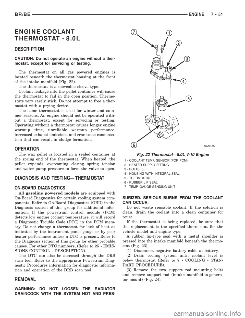
The thermostat on all gas powered engines is
located beneath the thermostat housing at the front
of the intake manifold (Fig. 22).
The thermostat is a moveable sleeve type.
Coolant leakage into the pellet container will cause
the thermostat to fail in the open position. Thermo-
stats very rarely stick. Do not attempt to free a ther-
mostat with a prying device.
The same thermostat is used for winter and sum-
mer seasons. An engine should not be operated with-
out a thermostat, except for servicing or testing.
Operating without a thermostat causes longer engine
warmup time, unreliable warmup performance,
increased exhaust emissions and crankcase condensa-
tion that can result in sludge formation.
OPERATION
The wax pellet is located in a sealed container at
the spring end of the thermostat. When heated, the
pellet expands, overcoming closing spring tension
and water pump pressure to force the valve to open.
DIAGNOSIS AND TESTINGÐTHERMOSTAT
ON-BOARD DIAGNOSTICS
Allgasoline powered modelsare equipped with
On-Board Diagnostics for certain cooling system com-
ponents. Refer to On-Board Diagnostics (OBD) in the
Diagnosis section of this group for additional infor-
mation. If the powertrain control module (PCM)
detects low engine coolant temperature, it will record
a Diagnostic Trouble Code (DTC) in the PCM mem-
ory. Do not change a thermostat for lack of heat as
indicated by the instrument panel gauge or by poor
heater performance unless a DTC is present. Refer to
the Diagnosis section of this group for other probable
causes. For other DTC numbers, (Refer to 25 - EMIS-
SIONS CONTROL - DESCRIPTION).
The DTC can also be accessed through the DRB
scan tool. Refer to the appropriate Powertrain Diag-
nostic Procedures information for diagnostic informa-
tion and operation of the DRB scan tool.
REMOVAL
WARNING: DO NOT LOOSEN THE RADIATOR
DRAINCOCK WITH THE SYSTEM HOT AND PRES-SURIZED. SERIOUS BURNS FROM THE COOLANT
CAN OCCUR.
Do not waste reusable coolant. If the solution is
clean, drain the coolant into a clean container for
reuse.
If the thermostat is being replaced, be sure that
the replacement is the specified thermostat for the
vehicle model and engine type.
A rubber lip-type seal with a metal shoulder is
pressed into the intake manifold beneath the thermo-
stat (Fig. 23).
(1) Disconnect negative battery cable at battery.
(2) Drain cooling system until coolant level is
below thermostat (Refer to 7 - COOLING - STAN-
DARD PROCEDURE).
(3) Remove the two support rod mounting bolts
and remove support rod (intake manifold-to-genera-
tor mount) (Fig. 24).
Fig. 22 ThermostatÐ8.0L V-10 Engine
1 - COOLANT TEMP. SENSOR (FOR PCM)
2 - HEATER SUPPLY FITTING
3 - BOLTS (6)
4 - HOUSING WITH INTEGRAL SEAL
5 - THERMOSTAT
6 - RUBBER LIP SEAL
7 - TEMP. GAUGE SENDING UNIT
BR/BEENGINE 7 - 51