ECU DODGE RAM 2002 Service Repair Manual
[x] Cancel search | Manufacturer: DODGE, Model Year: 2002, Model line: RAM, Model: DODGE RAM 2002Pages: 2255, PDF Size: 62.07 MB
Page 1 of 2255
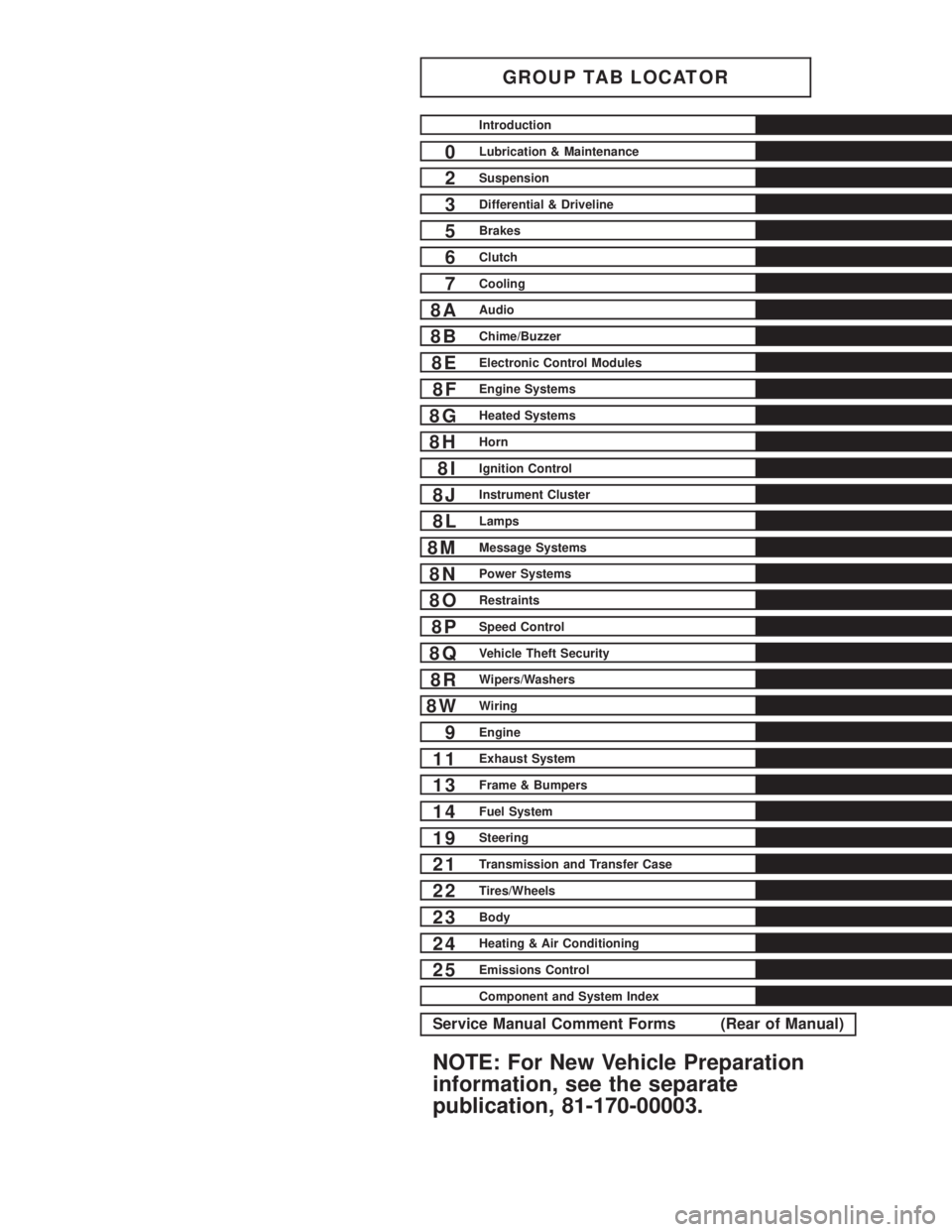
GROUP TAB LOCATOR
Introduction
0Lubrication & Maintenance
2Suspension
3Differential & Driveline
5Brakes
6Clutch
7Cooling
8AAudio
8BChime/Buzzer
8EElectronic Control Modules
8FEngine Systems
8GHeated Systems
8HHorn
8IIgnition Control
8JInstrument Cluster
8LLamps
8MMessage Systems
8NPower Systems
8ORestraints
8PSpeed Control
8QVehicle Theft Security
8RWipers/Washers
8WWiring
9Engine
11Exhaust System
13Frame & Bumpers
14Fuel System
19Steering
21Transmission and Transfer Case
22Tires/Wheels
23Body
24Heating & Air Conditioning
25Emissions Control
Component and System Index
Service Manual Comment Forms (Rear of Manual)
NOTE: For New Vehicle Preparation
information, see the separate
publication, 81-170-00003.
Page 22 of 2255
HOISTING
STANDARD PROCEDURE - HOISTING
Refer to the Owner's Manual for emergency vehicle
lifting procedures.
WARNING: THE HOISTING AND JACK LIFTING
POINTS PROVIDED ARE FOR A COMPLETE VEHI-
CLE. WHEN A CHASSIS OR DRIVETRAIN COMPO-
NENT IS REMOVED FROM A VEHICLE, THE
CENTER OF GRAVITY IS ALTERED MAKING SOME
HOISTING CONDITIONS UNSTABLE. PROPERLY
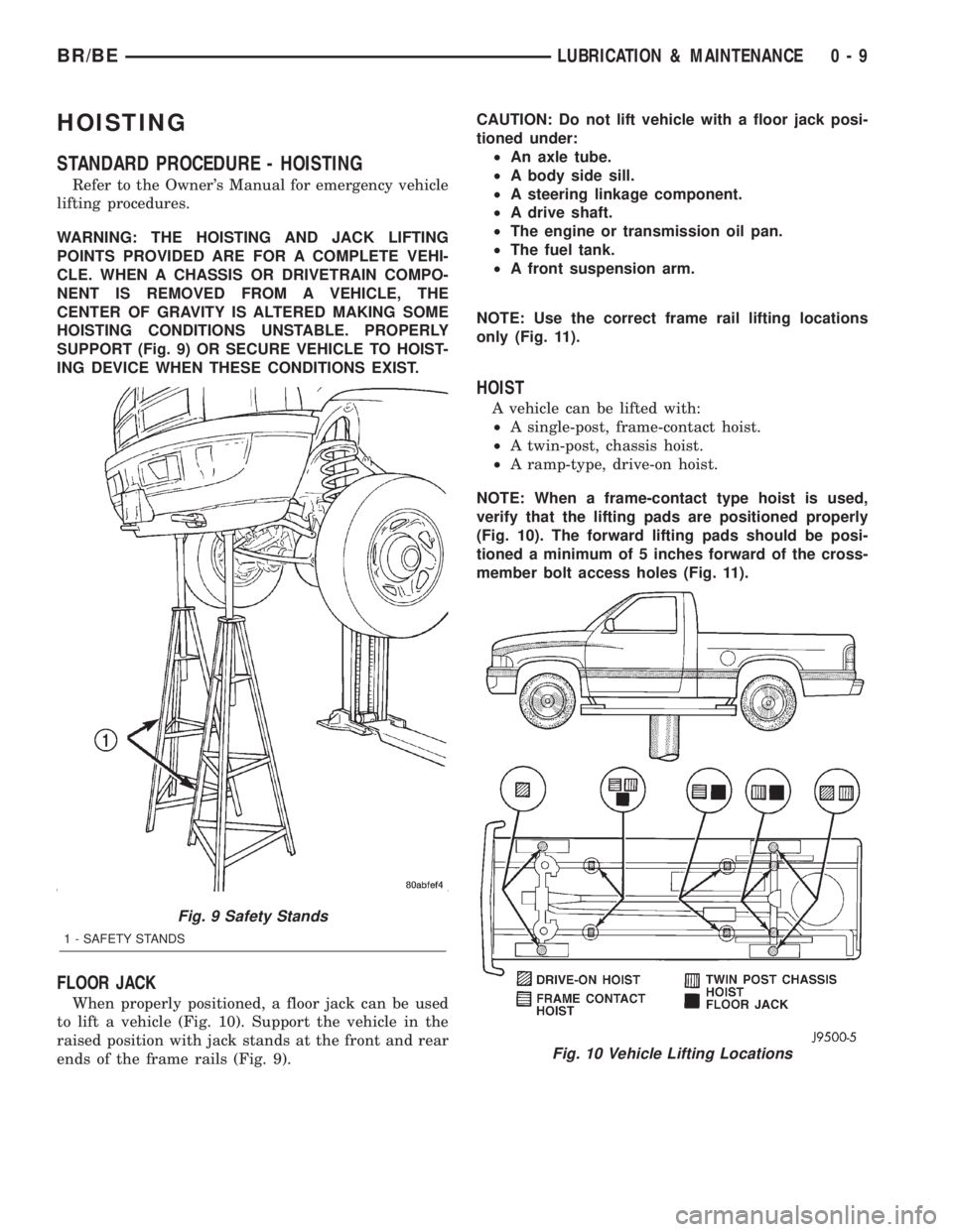
SUPPORT (Fig. 9) OR SECURE VEHICLE TO HOIST-
ING DEVICE WHEN THESE CONDITIONS EXIST.
FLOOR JACK
When properly positioned, a floor jack can be used
to lift a vehicle (Fig. 10). Support the vehicle in the
raised position with jack stands at the front and rear
ends of the frame rails (Fig. 9).CAUTION: Do not lift vehicle with a floor jack posi-
tioned under:
²An axle tube.
²A body side sill.
²A steering linkage component.
²A drive shaft.
²The engine or transmission oil pan.
²The fuel tank.
²A front suspension arm.
NOTE: Use the correct frame rail lifting locations
only (Fig. 11).
HOIST
A vehicle can be lifted with:
²A single-post, frame-contact hoist.
²A twin-post, chassis hoist.
²A ramp-type, drive-on hoist.
NOTE: When a frame-contact type hoist is used,
verify that the lifting pads are positioned properly
(Fig. 10). The forward lifting pads should be posi-
tioned a minimum of 5 inches forward of the cross-
member bolt access holes (Fig. 11).
Fig. 9 Safety Stands
1 - SAFETY STANDS
Fig. 10 Vehicle Lifting Locations
BR/BELUBRICATION & MAINTENANCE 0 - 9
Page 23 of 2255
TOWING
STANDARD PROCEDURE - TOWING
A vehicle equipped with SAE approved sling-type
towing equipment can be used to tow all vehicles.
When towing a 4WD vehicle using a wheel-lift towing
device, use tow dollies under the opposite end of the
vehicle. A vehicle with flat-bed device can also be
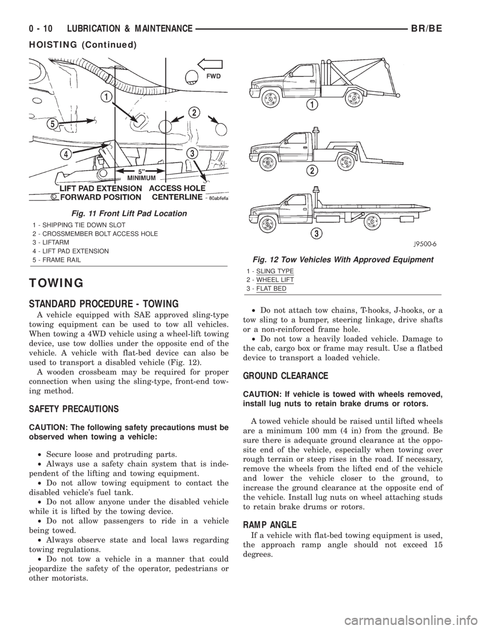
used to transport a disabled vehicle (Fig. 12).
A wooden crossbeam may be required for proper
connection when using the sling-type, front-end tow-
ing method.
SAFETY PRECAUTIONS
CAUTION: The following safety precautions must be
observed when towing a vehicle:
²Secure loose and protruding parts.
²Always use a safety chain system that is inde-
pendent of the lifting and towing equipment.
²Do not allow towing equipment to contact the
disabled vehicle's fuel tank.
²Do not allow anyone under the disabled vehicle
while it is lifted by the towing device.
²Do not allow passengers to ride in a vehicle
being towed.
²Always observe state and local laws regarding
towing regulations.
²Do not tow a vehicle in a manner that could
jeopardize the safety of the operator, pedestrians or
other motorists.²Do not attach tow chains, T-hooks, J-hooks, or a
tow sling to a bumper, steering linkage, drive shafts
or a non-reinforced frame hole.
²Do not tow a heavily loaded vehicle. Damage to
the cab, cargo box or frame may result. Use a flatbed
device to transport a loaded vehicle.
GROUND CLEARANCE
CAUTION: If vehicle is towed with wheels removed,
install lug nuts to retain brake drums or rotors.
A towed vehicle should be raised until lifted wheels
are a minimum 100 mm (4 in) from the ground. Be
sure there is adequate ground clearance at the oppo-
site end of the vehicle, especially when towing over
rough terrain or steep rises in the road. If necessary,
remove the wheels from the lifted end of the vehicle
and lower the vehicle closer to the ground, to
increase the ground clearance at the opposite end of
the vehicle. Install lug nuts on wheel attaching studs
to retain brake drums or rotors.
RAMP ANGLE
If a vehicle with flat-bed towing equipment is used,
the approach ramp angle should not exceed 15
degrees.
Fig. 11 Front Lift Pad Location
1 - SHIPPING TIE DOWN SLOT
2 - CROSSMEMBER BOLT ACCESS HOLE
3 - LIFTARM
4 - LIFT PAD EXTENSION
5 - FRAME RAIL
Fig. 12 Tow Vehicles With Approved Equipment
1 - SLING TYPE
2 - WHEEL LIFT
3 - FLAT BED
0 - 10 LUBRICATION & MAINTENANCEBR/BE
HOISTING (Continued)
Page 24 of 2255
TOWING WHEN KEYS ARE NOT AVAILABLE
When the vehicle is locked and keys are not avail-
able, use a flat bed hauler. A Wheel-lift or Sling-type
device can be used on 4WD vehicles providedall the
wheels are lifted off the ground using tow dol-
lies.
FOUR-WHEEL-DRIVE VEHICLE TOWING
Chrysler Corporation recommends that a vehicle be
transported on a flat-bed device. A Wheel-lift or
Sling-type device can be used providedall the
wheels are lifted off the ground using tow dol-
lies.WARNING: WHEN TOWING A DISABLED VEHICLE
AND THE DRIVE WHEELS ARE SECURED IN A
WHEEL LIFT OR TOW DOLLIES, ENSURE THE
TRANSMISSION IS IN THE PARK POSITION (AUTO-
MATIC TRANSMISSION) OR A FORWARD DRIVE
GEAR (MANUAL TRANSMISSION).
CAUTION: Many vehicles are equipped with air
dams, spoilers, and/or ground effect panels. To
avoid component damage, a wheel-lift towing vehi-
cle or a flat-bed hauling vehicle is recommended.
BR/BELUBRICATION & MAINTENANCE 0 - 11
TOWING (Continued)
Page 28 of 2255
STANDARD PROCEDURE
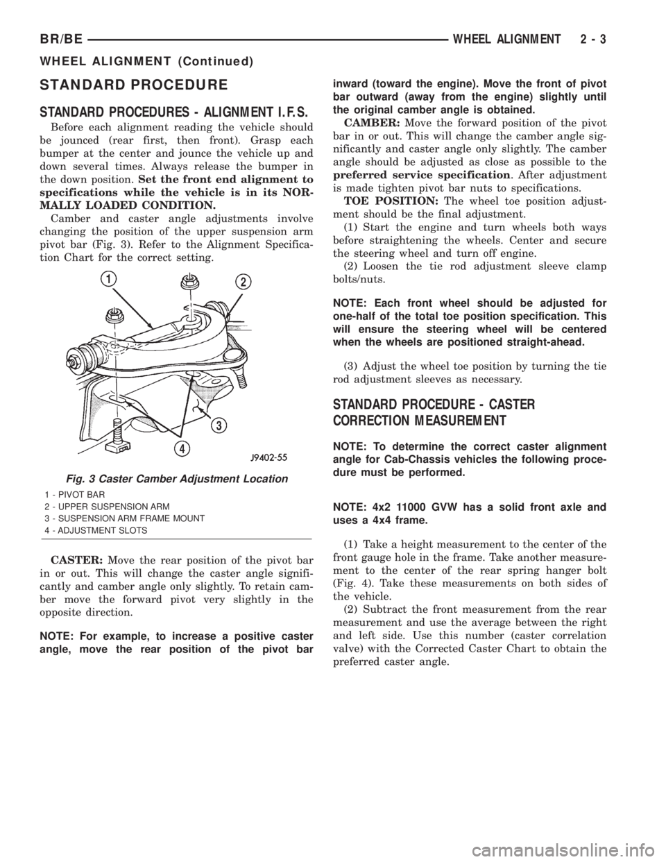
STANDARD PROCEDURES - ALIGNMENT I.F.S.
Before each alignment reading the vehicle should
be jounced (rear first, then front). Grasp each
bumper at the center and jounce the vehicle up and
down several times. Always release the bumper in
the down position.Set the front end alignment to
specifications while the vehicle is in its NOR-
MALLY LOADED CONDITION.
Camber and caster angle adjustments involve
changing the position of the upper suspension arm
pivot bar (Fig. 3). Refer to the Alignment Specifica-
tion Chart for the correct setting.
CASTER:Move the rear position of the pivot bar
in or out. This will change the caster angle signifi-
cantly and camber angle only slightly. To retain cam-
ber move the forward pivot very slightly in the
opposite direction.
NOTE: For example, to increase a positive caster
angle, move the rear position of the pivot barinward (toward the engine). Move the front of pivot
bar outward (away from the engine) slightly until
the original camber angle is obtained.
CAMBER:Move the forward position of the pivot
bar in or out. This will change the camber angle sig-
nificantly and caster angle only slightly. The camber
angle should be adjusted as close as possible to the
preferred service specification. After adjustment
is made tighten pivot bar nuts to specifications.
TOE POSITION:The wheel toe position adjust-
ment should be the final adjustment.
(1) Start the engine and turn wheels both ways
before straightening the wheels. Center and secure
the steering wheel and turn off engine.
(2) Loosen the tie rod adjustment sleeve clamp
bolts/nuts.
NOTE: Each front wheel should be adjusted for
one-half of the total toe position specification. This
will ensure the steering wheel will be centered
when the wheels are positioned straight-ahead.
(3) Adjust the wheel toe position by turning the tie
rod adjustment sleeves as necessary.
STANDARD PROCEDURE - CASTER
CORRECTION MEASUREMENT
NOTE: To determine the correct caster alignment
angle for Cab-Chassis vehicles the following proce-
dure must be performed.
NOTE: 4x2 11000 GVW has a solid front axle and
uses a 4x4 frame.
(1) Take a height measurement to the center of the
front gauge hole in the frame. Take another measure-
ment to the center of the rear spring hanger bolt
(Fig. 4). Take these measurements on both sides of
the vehicle.
(2) Subtract the front measurement from the rear
measurement and use the average between the right
and left side. Use this number (caster correlation
valve) with the Corrected Caster Chart to obtain the
preferred caster angle.
Fig. 3 Caster Camber Adjustment Location
1 - PIVOT BAR
2 - UPPER SUSPENSION ARM
3 - SUSPENSION ARM FRAME MOUNT
4 - ADJUSTMENT SLOTS
BR/BEWHEEL ALIGNMENT 2 - 3
WHEEL ALIGNMENT (Continued)
Page 30 of 2255
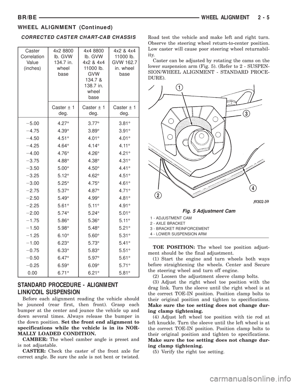
CORRECTED CASTER CHART-CAB CHASSIS
Caster
Correlation
Value
(inches)4x2 8800
lb. GVW
134.7 in.
wheel
base4x4 8800
lb. GVW
4x2 & 4x4
11000 lb.
GVW
134.7 &
138.7 in.
wheel
base4x2 & 4x4
11000 lb.
GVW 162.7
in. wheel
base
Caster 1
deg.Caster 1
deg.Caster 1
deg.
25.00 4.27É 3.77É 3.81É
24.75 4.39É 3.89É 3.91É
24.50 4.51É 4.01É 4.01É
24.25 4.64É 4.14É 4.11É
24.00 4.76É 4.26É 4.21É
23.75 4.88É 4.38É 4.31É
23.50 5.00É 4.50É 4.41É
23.25 5.12É 4.62É 4.51É
23.00 5.25É 4.75É 4.61É
22.75 5.37É 4.87É 4.71É
22.50 5.49É 4.99É 4.81É
22.25 5.61É 5.11É 4.91É
22.00 5.74É 5.24É 5.01É
21.75 5.86É 5.36É 5.11É
21.50 5.98É 5.48É 5.21É
21.25 6.10É 5.60É 5.31É
21.00 6.23É 5.73É 5.41É
20.75 6.33É 5.83É 5.51É
20.50 6.47É 5.97É 5.61É
20.25 6.59É 6.09É 5.71É
0.00 6.71É 6.21É 5.81É
STANDARD PROCEDURE - ALIGNMENT
LINK/COIL SUSPENSION
Before each alignment reading the vehicle should
be jounced (rear first, then front). Grasp each
bumper at the center and jounce the vehicle up and
down several times. Always release the bumper in
the down position.Set the front end alignment to
specifications while the vehicle is in its NOR-
MALLY LOADED CONDITION.
CAMBER:The wheel camber angle is preset and
is not adjustable.
CASTER:Check the caster of the front axle for
correct angle. Be sure the axle is not bent or twisted.Road test the vehicle and make left and right turn.
Observe the steering wheel return-to-center position.
Low caster will cause poor steering wheel returnabil-
ity.
Caster can be adjusted by rotating the cams on the
lower suspension arm (Fig. 5). (Refer to 2 - SUSPEN-
SION/WHEEL ALIGNMENT - STANDARD PROCE-
DURE).
TOE POSITION:The wheel toe position adjust-
ment should be the final adjustment.
(1) Start the engine and turn wheels both ways
before straightening the wheels. Center and Secure
the steering wheel and turn off engine.
(2) Loosen the adjustment sleeve clamp bolts.
(3) Adjust the right wheel toe position with the
drag link. Turn the sleeve until the right wheel is at
the correct TOE-IN position. Position clamp bolts to
their original position and tighten to specifications.
Make sure the toe setting does not change dur-
ing clamp tightening.
(4) Adjust left wheel toe position with tie rod at
left knuckle. Turn the sleeve until the left wheel is at
the correct TOE-IN position. Position clamp bolts to
their original position and tighten to specifications.
Make sure the toe setting does not change dur-
ing clamp tightening.
(5) Verify the right toe setting.
Fig. 5 Adjustment Cam
1 - ADJUSTMENT CAM
2 - AXLE BRACKET
3 - BRACKET REINFORCEMENT
4 - LOWER SUSPENSION ARM
BR/BEWHEEL ALIGNMENT 2 - 5
WHEEL ALIGNMENT (Continued)
Page 73 of 2255
Condition Possible Causes Correction
Gear Teeth Broke 1. Overloading. 1. Replace gears. Examine other
gears and bearings for possible
damage.
2. Erratic clutch operation. 2. Replace gears and examine the
remaining parts for damage. Avoid
erratic clutch operation.
3. Ice-spotted pavement. 3. Replace gears and examine
remaining parts for damage.
4. Improper adjustments. 4. Replace gears and examine
remaining parts for damage. Ensure
ring gear backlash is correct.
Axle Noise 1. Insufficient lubricant. 1. Fill differential with the correct
fluid type and quantity.
2. Improper ring gear and pinion
adjustment.2. Check ring gear and pinion
contact pattern.
3. Unmatched ring gear and pinion. 3. Replace gears with a matched
ring gear and pinion.
4. Worn teeth on ring gear and/or
pinion.4. Replace ring gear and pinion.
5. Loose pinion bearings. 5. Adjust pinion bearing pre-load.
6. Loose differential bearings. 6. Adjust differential bearing
pre-load.
7. Mis-aligned or sprung ring gear. 7. Measure ring gear run-out.
Replace components as necessary.
8. Loose differential bearing cap
bolts.8. Inspect differential components
and replace as necessary. Ensure
that the bearing caps are torqued
tot he proper specification.
9. Housing not machined properly. 9. Replace housing.
REMOVAL
(1) Raise and support the vehicle.
(2) Remove wheels and tires.
(3) Remove brake calipers and rotors. Refer to 5
Brakes for procedures.
(4) Remove ABS wheel speed sensors, if equipped.
Refer to 5 Brakes for procedures.
(5) Disconnect axle vent hose.
(6) Disconnect vacuum hose and electrical connec-
tor at disconnect housing.
(7) Remove front propeller shaft.
(8) Disconnect stabilizer bar links at the axle
brackets.
(9) Disconnect shock absorbers from axle brackets.
(10) Disconnect track bar from the axle bracket.
(11) Disconnect tie rod and drag link from the
steering knuckles.
(12) Position suitable lifting device under the axle
assembly.(13) Secure axle to lifting device.
(14) Mark suspension alignment cams for installa-
tion reference.
(15) Disconnect upper and lower suspension arms
from the axle bracket.
(16) Lower the axle. The coil springs will drop
with the axle.
(17) Remove the coil springs from the axle bracket.
INSTALLATION
CAUTION: Suspension components with rubber
bushings should be tightened with the weight of the
vehicle on the suspension, at normal height. If
springs are not at their normal ride position, vehicle
ride comfort could be affected and premature bush-
ing wear may occur. Rubber bushings must never
be lubricated.
(1) Support the axle on a suitable lifting device.
3 - 18 FRONT AXLE - 248FBIBR/BE
FRONT AXLE - 248FBI (Continued)
Page 74 of 2255
(2) Secure axle to lifting device.
(3) Position the axle under the vehicle.
(4) Install springs, retainer clip and bolts.
(5) Raise axle and align it with the spring pads.
(6) Position upper and lower suspension arms in
the axle brackets. Install bolts, nuts and align the
suspension alignment cams to the reference marks.
Do not tighten at this time.
(7) Connect track bar to the axle bracket and
install the bolt. Do not tighten at this time.
(8) Install shock absorber and tighten bolts to 121
N´m (89 ft. lbs.).
(9) Install stabilizer bar link to the axle bracket.
Tighten the nut to 37 N´m (27 ft. lbs.).
(10) Install drag link and tie rod to the steering
knuckles and tighten the nuts to 88 N´m (65 ft. lbs.).
(11) Install ABS wheel speed sensors, if equipped.
Refer to 5 Brakes for procedures.
(12) Install rotors and brake calipers, refer to 5
Brakes for procedures.
(13) Connect the vent hose to the tube fitting.
(14) Connect vacuum hose and electrical connector
to disconnect housing.
(15) Install front propeller shaft.
(16) Check and add differential lubricant, if neces-
sary. Refer to Lubricant Specifications for lubricant
requirements.
(17) Install wheel and tire assemblies.
(18) Remove supports and lower the vehicle.
(19) Tighten upper suspension arm nuts at axle to
121 N´m (89 ft. lbs.). Tighten upper suspension arm
nuts at frame to 84 N´m (62 ft. lbs.).
(20) Tighten lower suspension arm nuts at axle to
84 N´m (62 ft. lbs.). Tighten the lower suspension
arm nuts at frame to 119 N´m (88 ft. lbs.).
(21) Tighten track bar bolt at the axle bracket to
176 N´m (130 ft. lbs.).
(22) Check front wheel alignment.
ADJUSTMENTS
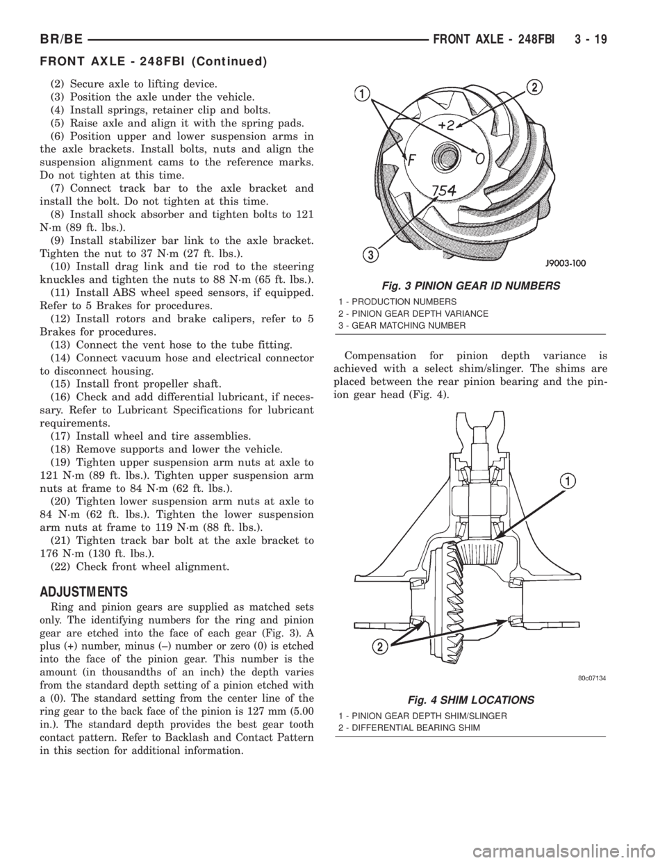
Ring and pinion gears are supplied as matched sets
only. The identifying numbers for the ring and pinion
gear are etched into the face of each gear (Fig. 3). A
plus (+) number, minus (±) number or zero (0) is etched
into the face of the pinion gear. This number is the
amount (in thousandths of an inch) the depth varies
from the standard depth setting of a pinion etched with
a (0). The standard setting from the center line of the
ring gear to the back face of the pinion is 127 mm (5.00
in.). The standard depth provides the best gear tooth
contact pattern. Refer to Backlash and Contact Pattern
in this section for additional information.
Compensation for pinion depth variance is
achieved with a select shim/slinger. The shims are
placed between the rear pinion bearing and the pin-
ion gear head (Fig. 4).
Fig. 3 PINION GEAR ID NUMBERS
1 - PRODUCTION NUMBERS
2 - PINION GEAR DEPTH VARIANCE
3 - GEAR MATCHING NUMBER
Fig. 4 SHIM LOCATIONS
1 - PINION GEAR DEPTH SHIM/SLINGER
2 - DIFFERENTIAL BEARING SHIM
BR/BEFRONT AXLE - 248FBI 3 - 19
FRONT AXLE - 248FBI (Continued)
Page 76 of 2255
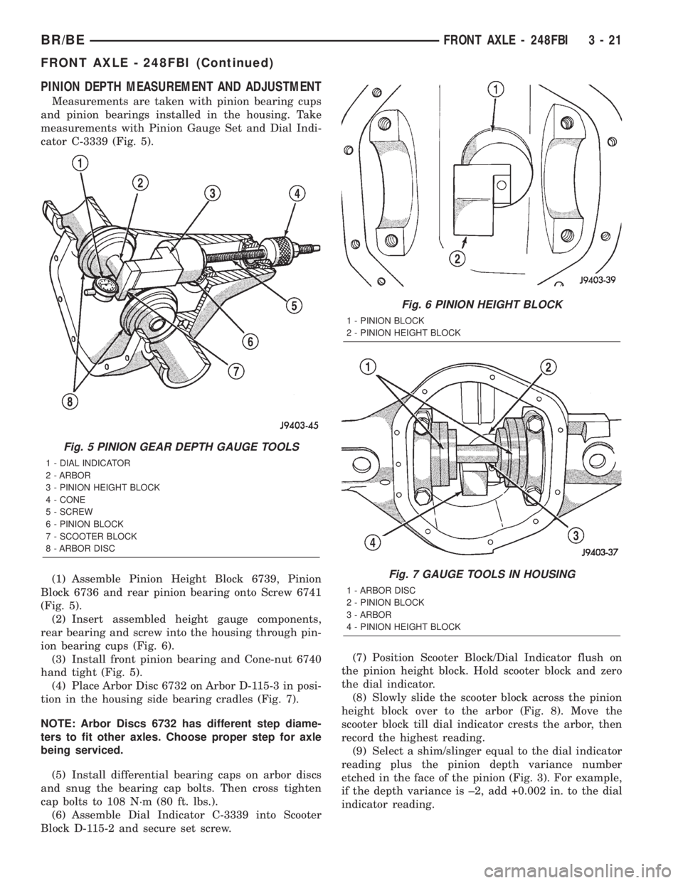
PINION DEPTH MEASUREMENT AND ADJUSTMENT
Measurements are taken with pinion bearing cups
and pinion bearings installed in the housing. Take
measurements with Pinion Gauge Set and Dial Indi-
cator C-3339 (Fig. 5).
(1) Assemble Pinion Height Block 6739, Pinion
Block 6736 and rear pinion bearing onto Screw 6741
(Fig. 5).
(2) Insert assembled height gauge components,
rear bearing and screw into the housing through pin-
ion bearing cups (Fig. 6).
(3) Install front pinion bearing and Cone-nut 6740
hand tight (Fig. 5).
(4) Place Arbor Disc 6732 on Arbor D-115-3 in posi-
tion in the housing side bearing cradles (Fig. 7).
NOTE: Arbor Discs 6732 has different step diame-
ters to fit other axles. Choose proper step for axle
being serviced.
(5) Install differential bearing caps on arbor discs
and snug the bearing cap bolts. Then cross tighten
cap bolts to 108 N´m (80 ft. lbs.).
(6) Assemble Dial Indicator C-3339 into Scooter
Block D-115-2 and secure set screw.(7) Position Scooter Block/Dial Indicator flush on
the pinion height block. Hold scooter block and zero
the dial indicator.
(8) Slowly slide the scooter block across the pinion
height block over to the arbor (Fig. 8). Move the
scooter block till dial indicator crests the arbor, then
record the highest reading.
(9) Select a shim/slinger equal to the dial indicator
reading plus the pinion depth variance number
etched in the face of the pinion (Fig. 3). For example,
if the depth variance is ±2, add +0.002 in. to the dial
indicator reading.
Fig. 5 PINION GEAR DEPTH GAUGE TOOLS
1 - DIAL INDICATOR
2 - ARBOR
3 - PINION HEIGHT BLOCK
4 - CONE
5 - SCREW
6 - PINION BLOCK
7 - SCOOTER BLOCK
8 - ARBOR DISC
Fig. 6 PINION HEIGHT BLOCK
1 - PINION BLOCK
2 - PINION HEIGHT BLOCK
Fig. 7 GAUGE TOOLS IN HOUSING
1 - ARBOR DISC
2 - PINION BLOCK
3 - ARBOR
4 - PINION HEIGHT BLOCK
BR/BEFRONT AXLE - 248FBI 3 - 21
FRONT AXLE - 248FBI (Continued)
Page 106 of 2255
REMOVAL
(1) Raise and support the vehicle.
(2) Position an axle lift under the axle and secure
it to the axle.
(3) Remove the wheels and tires.
(4) Remove RWAL sensor from the differential
housing, if necessary.
(5) Remove brake hose from the axle junction
block.
(6) Disconnect parking brake cables and cable
brackets.
(7) Remove vent hose from the axle shaft tube.
(8) Mark propeller shaft and yoke for installation
alignment reference.
(9) Remove propeller shaft.
(10) Remove shock absorbers from the axle brack-
ets.
(11) Remove spring clamps and spring brackets.
(12) Remove axle from the vehicle.
INSTALLATION
(1) Raise axle with lift and align to the leaf spring
centering bolts.
(2) Install spring clamps and spring brackets.
(3) Install shock absorbers and tighten to specifica-
tions.
(4) Install RWAL sensor to the differential hous-
ing, if necessary.
(5) Install parking brake cables and cable brackets
(6) Install brake hose to the axle junction block.
(7) Install axle vent hose.
(8) Install propeller shaft with reference marks
aligned.
(9) Install wheels and tires assemblies.
(10) Add gear lubricant, if necessary.
(11) Remove lift from the axle and lower the vehi-
cle.
ADJUSTMENTS
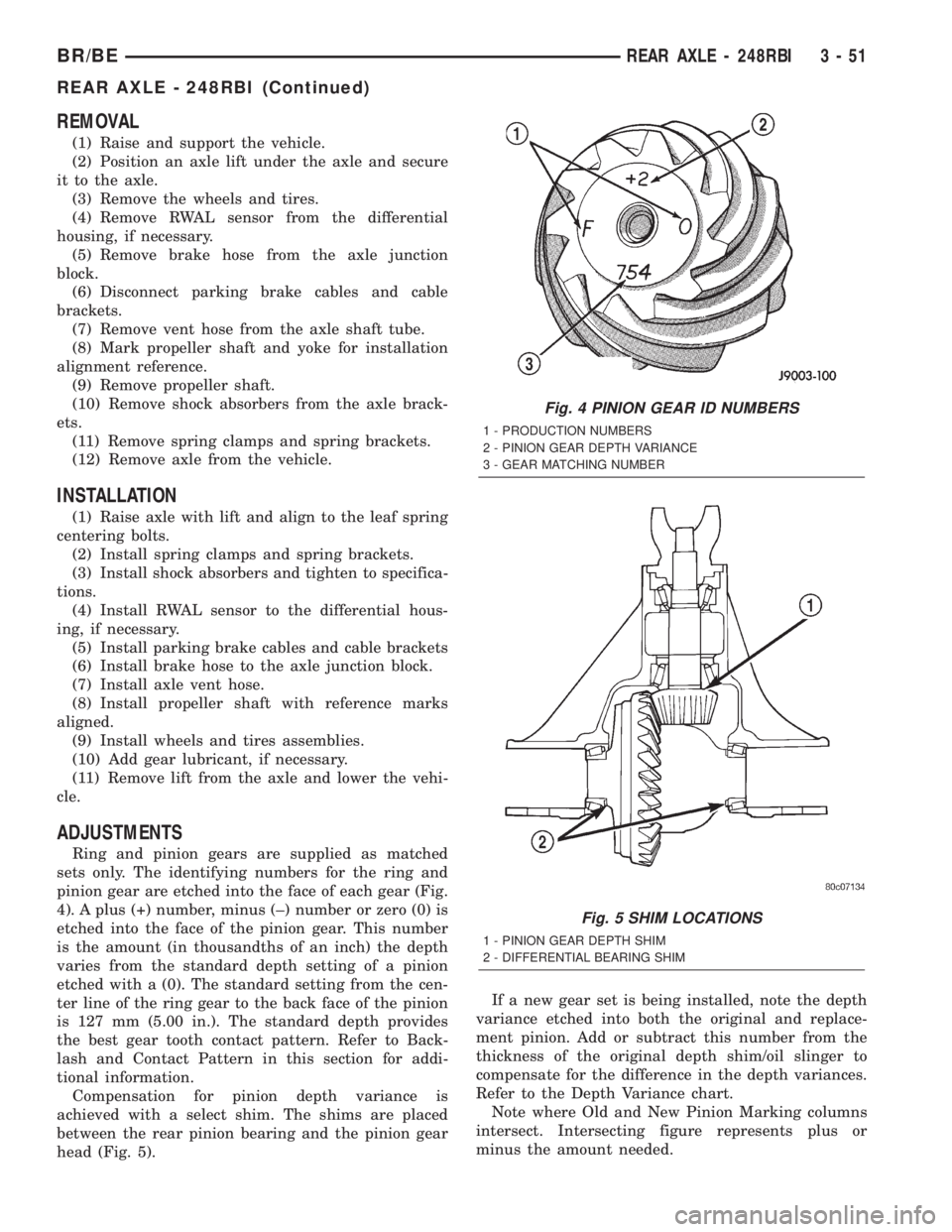
Ring and pinion gears are supplied as matched
sets only. The identifying numbers for the ring and
pinion gear are etched into the face of each gear (Fig.
4). A plus (+) number, minus (±) number or zero (0) is
etched into the face of the pinion gear. This number
is the amount (in thousandths of an inch) the depth
varies from the standard depth setting of a pinion
etched with a (0). The standard setting from the cen-
ter line of the ring gear to the back face of the pinion
is 127 mm (5.00 in.). The standard depth provides
the best gear tooth contact pattern. Refer to Back-
lash and Contact Pattern in this section for addi-
tional information.
Compensation for pinion depth variance is
achieved with a select shim. The shims are placed
between the rear pinion bearing and the pinion gear
head (Fig. 5).If a new gear set is being installed, note the depth
variance etched into both the original and replace-
ment pinion. Add or subtract this number from the
thickness of the original depth shim/oil slinger to
compensate for the difference in the depth variances.
Refer to the Depth Variance chart.
Note where Old and New Pinion Marking columns
intersect. Intersecting figure represents plus or
minus the amount needed.
Fig. 4 PINION GEAR ID NUMBERS
1 - PRODUCTION NUMBERS
2 - PINION GEAR DEPTH VARIANCE
3 - GEAR MATCHING NUMBER
Fig. 5 SHIM LOCATIONS
1 - PINION GEAR DEPTH SHIM
2 - DIFFERENTIAL BEARING SHIM
BR/BEREAR AXLE - 248RBI 3 - 51
REAR AXLE - 248RBI (Continued)