run flat DODGE RAM 2002 Service Repair Manual
[x] Cancel search | Manufacturer: DODGE, Model Year: 2002, Model line: RAM, Model: DODGE RAM 2002Pages: 2255, PDF Size: 62.07 MB
Page 58 of 2255
(15) If the vibration remains unacceptable, apply
the same steps to the front end of the propeller shaft.
(16) Install the wheel and tires. Lower the vehicle.
RUNOUT
(1) Remove dirt, rust, paint and undercoating from
the propeller shaft surface where the dial indicator
will contact the shaft.
(2) The dial indicator must be installed perpendic-
ular to the shaft surface.
(3) Measure runout at the center and ends of the
shaft sufficiently far away from weld areas to ensure
that the effects of the weld process will not enter into
the measurements.
(4) Refer to Runout Specifications chart.
(5) If propeller shaft runout is out of specification,
remove the propeller shaft, index the shaft 180É and
re-install the propeller shaft. Measure shaft runout
again.
(6) If propeller shaft runout is now within specifi-
cations, mark the shaft and yokes for proper orienta-
tion.
(7) If the propeller shaft runout is not within spec-
ifications, verify that the runout of the transmission/
transfer case and axle are within specifications.
Correct as necessary and re-measure propeller shaft
runout.
(8) Replace the propeller shaft if the runout still
exceeds the limits.
RUNOUT SPECIFICATIONS
Front of Shaft 0.020 in. (0.50 mm)
Center of Shaft 0.025 in. (0.63 mm)
Rear of Shaft 0.020 in. (0.50 mm)
note:
Measure front/rear runout approximately 3 inches (76
mm) from the weld seam at each end of the shaft
tube for tube lengths over 30 inches. For tube lengths
under 30 inches, the maximum allowed runout is
0.020 in. (0.50 mm) for the full length of the tube.
STANDARD PROCEDURES
To accurately check driveline alignment, raise and
support the vehicle at the axles as level as possible.
Allow the wheels and propeller shaft to turn.
(1) Remove any external bearing snap rings, if
equipped from universal joint so protractor base sits
flat.
(2) Rotate the shaft until transmission/transfer
case output yoke bearing is facing downward.
NOTE: Always make measurements from front to
rear and from the same side of the vehicle.
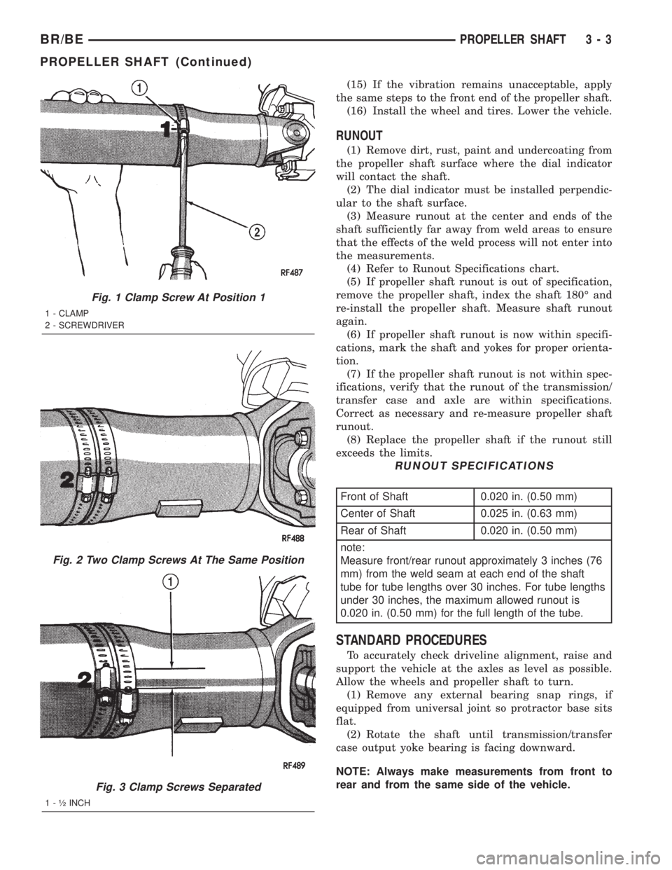
Fig. 1 Clamp Screw At Position 1
1 - CLAMP
2 - SCREWDRIVER
Fig. 2 Two Clamp Screws At The Same Position
Fig. 3 Clamp Screws Separated
1 - ó INCH
BR/BEPROPELLER SHAFT 3 - 3
PROPELLER SHAFT (Continued)
Page 194 of 2255
CAUTION: Never use gasoline, kerosene, alcohol,
motor oil, transmission fluid, or any fluid containing
mineral oil to clean the system components. These
fluids damage rubber cups and seals. Use only
fresh brake fluid or Mopar brake cleaner to clean or
flush brake system components. These are the only
cleaning materials recommended. If system contam-
ination is suspected, check the fluid for dirt, discol-
oration, or separation into distinct layers. Also
check the reservoir cap seal for distortion. Drain
and flush the system with new brake fluid if con-
tamination is suspected.
CAUTION: Use Mopar brake fluid, or an equivalent
quality fluid meeting SAE/DOT standards J1703 and
DOT 3. Brake fluid must be clean and free of con-
taminants. Use fresh fluid from sealed containers
only to ensure proper antilock component opera-
tion.
CAUTION: Use Mopar multi-mileage or high temper-
ature grease to lubricate caliper slide surfaces,
drum brake pivot pins, and shoe contact points on
the backing plates. Use multi-mileage grease or GE
661 or Dow 111 silicone grease on caliper slide pins
to ensure proper operation.
DIAGNOSIS AND TESTING - BASE BRAKE
SYSTEM
Base brake components consist of the brake shoes,
calipers, wheel cylinders, brake drums, rotors, brake
lines, master cylinder, booster, and parking brake
components.
Brake diagnosis involves determining if the prob-
lem is related to a mechanical, hydraulic, or vacuum
operated component.
The first diagnosis step is the preliminary check.
PRELIMINARY BRAKE CHECK
(1) Check condition of tires and wheels. Damaged
wheels and worn, damaged, or underinflated tires
can cause pull, shudder, vibration, and a condition
similar to grab.
(2) If complaint was based on noise when braking,
check suspension components. Jounce front and rear
of vehicle and listen for noise that might be caused
by loose, worn or damaged suspension or steering
components.
(3) Inspect brake fluid level and condition. Note
that the brake reservoir fluid level will decrease in
proportion to normal lining wear.Also note that
brake fluid tends to darken over time. This is
normal and should not be mistaken for contam-
ination.(a) If fluid level is abnormally low, look for evi-
dence of leaks at calipers, wheel cylinders, brake
lines, and master cylinder.
(b) If fluid appears contaminated, drain out a
sample to examine. System will have to be flushed
if fluid is separated into layers, or contains a sub-
stance other than brake fluid. The system seals
and cups will also have to be replaced after flush-
ing. Use clean brake fluid to flush the system.
(4) Check parking brake operation. Verify free
movement and full release of cables and pedal. Also
note if vehicle was being operated with parking
brake partially applied.
(5) Check brake pedal operation. Verify that pedal
does not bind and has adequate free play. If pedal
lacks free play, check pedal and power booster for
being loose or for bind condition. Do not road test
until condition is corrected.
(6) Check booster vacuum check valve and hose.
(7) If components checked appear OK, road test
the vehicle.
ROAD TESTING
(1) If complaint involved low brake pedal, pump
pedal and note if it comes back up to normal height.
(2) Check brake pedal response with transmission
in Neutral and engine running. Pedal should remain
firm under constant foot pressure.
(3) During road test, make normal and firm brake
stops in 25-40 mph range. Note faulty brake opera-
tion such as low pedal, hard pedal, fade, pedal pulsa-
tion, pull, grab, drag, noise, etc.
(4) Attempt to stop the vehicle with the parking
brake only and note grab, drag, noise, etc.
PEDAL FALLS AWAY
A brake pedal that falls away under steady foot
pressure is generally the result of a system leak. The
leak point could be at a brake line, fitting, hose, or
caliper/wheel cylinder. If leakage is severe, fluid will
be evident at or around the leaking component.
Internal leakage (seal by-pass) in the master cylin-
der caused by worn or damaged piston cups, may
also be the problem cause.
An internal leak in the ABS or RWAL system may
also be the problem with no physical evidence.
LOW PEDAL
If a low pedal is experienced, pump the pedal sev-
eral times. If the pedal comes back up, worn linings,
rotors, drums, or rear brakes out of adjustment are
the most likely causes. The proper course of action is
to inspect and replace all worn component and make
the proper adjustments.
BR/BEBRAKES - BASE 5 - 5
HYDRAULIC/MECHANICAL (Continued)
Page 597 of 2255
WARNING: WHEN A STEERING COLUMN HAS AN
AIRBAG UNIT ATTACHED, NEVER PLACE THE COL-
UMN ON THE FLOOR OR ANY OTHER SURFACE
WITH THE STEERING WHEEL OR AIRBAG UNIT
FACE DOWN.
DIAGNOSIS AND TESTING - AIRBAG SYSTEM
Proper diagnosis and testing of the airbag system
components, the Chrysler Collision Detection (CCD)
data bus, the data bus message inputs to and out-
puts from the ElectroMechanical Instrument Cluster
(EMIC) or the Airbag Control Module (ACM), as well
as the retrieval or erasure of a Diagnostic Trouble
Code (DTC) from the ACM requires the use of a
DRBIIItscan tool. Refer to the appropriate diagnos-
tic information.
WARNING: ON VEHICLES EQUIPPED WITH AIR-
BAGS, DISABLE THE AIRBAG SYSTEM BEFORE
ATTEMPTING ANY STEERING WHEEL, STEERING
COLUMN, OR INSTRUMENT PANEL COMPONENT
DIAGNOSIS OR SERVICE. DISCONNECT AND ISO-
LATE THE BATTERY NEGATIVE (GROUND) CABLE,
THEN WAIT TWO MINUTES FOR THE AIRBAG SYS-
TEM CAPACITOR TO DISCHARGE BEFORE PER-
FORMING FURTHER DIAGNOSIS OR SERVICE. THIS
IS THE ONLY SURE WAY TO DISABLE THE AIRBAG
SYSTEM. FAILURE TO TAKE THE PROPER PRE-
CAUTIONS COULD RESULT IN ACCIDENTAL AIR-
BAG DEPLOYMENT AND POSSIBLE PERSONAL
INJURY.
STANDARD PROCEDURE
STANDARD PROCEDURE - HANDLING
NON-DEPLOYED AIRBAGS
At no time should any source of electricity be per-
mitted near the inflator on the back of a non-de-
ployed airbag. When carrying a non-deployed airbag,
the trim cover or airbag cushion side of the unit
should be pointed away from the body to minimize
injury in the event of an accidental deployment. If
the airbag unit is placed on a bench or any other sur-
face, the trim cover or airbag cushion side of the unit
should be face up to minimize movement in the event
of an accidental deployment. In addition, the airbag
system should be disarmed whenever any steering
wheel, steering column, or instrument panel compo-
nents require diagnosis or service. Failure to observe
this warning could result in accidental airbag deploy-
ment and possible personal injury.
All damaged, faulty, or non-deployed airbags which
are replaced on vehicles are to handled and disposed
of properly. If an airbag unit is faulty or damagedand non-deployed, refer to the Hazardous Substance
Control System for proper disposal. Dispose of all
non-deployed and deployed airbags in a manner con-
sistent with state, provincial, local and federal regu-
lations.
AIRBAG STORAGE
An airbag must be stored in its original, special
container until it is used for service. Also, it must be
stored in a clean, dry environment; away from
sources of extreme heat, sparks, and high electrical
energy. Always place or store any airbag on a surface
with its trim cover or airbag cushion side facing up,
to minimize movement in case of an accidental
deployment.
STANDARD PROCEDURE - SERVICE AFTER AN
AIRBAG DEPLOYMENT
Any vehicle which is to be returned to use follow-
ing an airbag deployment, must have both airbags,
the driver airbag trim cover, the clockspring, and the
steering column assembly replaced. These compo-
nents are not intended for reuse and will be damaged
or weakened as a result of an airbag deployment,
which may or may not be obvious during a visual
inspection. Other vehicle components should be
closely inspected, but are to be replaced only as
required by the extent of the visible damage
incurred.
CLEANUP PROCEDURE
Following an airbag deployment, the vehicle inte-
rior will contain a powdery residue. This residue con-
sists primarily of harmless particulate by-products of
the small pyrotechnic charge used to initiate the pro-
pellant used to deploy the airbags. However, this res-
idue may also contain traces of sodium hydroxide
powder, a chemical by-product of the propellant
material that is used to generate the nitrogen gas
that inflates the airbag. Since sodium hydroxide pow-
der can irritate the skin, eyes, nose, or throat, be
sure to wear safety glasses, rubber gloves, and a
long-sleeved shirt during cleanup (Fig. 2).
WARNING: IF YOU EXPERIENCE SKIN IRRITATION
DURING CLEANUP, RUN COOL WATER OVER THE
AFFECTED AREA. ALSO, IF YOU EXPERIENCE
IRRITATION OF THE NOSE OR THROAT, EXIT THE
VEHICLE FOR FRESH AIR UNTIL THE IRRITATION
CEASES. IF IRRITATION CONTINUES, SEE A PHYSI-
CIAN.
Begin the cleanup by removing both airbags from
the vehicle. Refer to the appropriate service removal
procedures.
8O - 4 RESTRAINTSBR/BE
RESTRAINTS (Continued)
Page 1091 of 2255
DESCRIPTION SPECIFICATION
Switch Actuating
Pressure34.5 ± 48.3 kPa (5 ± 7
psi)
* If oil pressure is zero at curb idle, DO NOT RUN
ENGINE.
OIL PUMP
Clearance over Rotors
(Max.)0.1016 mm (0.004 in.)
Cover Out of Flat (Max.) 0.0381 mm (0.0015 in.)
Inner Rotor Thickness
(Min.)20.955 mm (0.825 in.)
Outer Rotor
Clearance (Max.) 0.3556 mm (0.014 in.)
Diameter (Min.) 62.7126 mm (2.469 in.)
Thickness (Min.) 20.955 mm (0.825 in.)
Tip Clearance between
Rotors (Max.) 0.2032 mm (0.008 in.)
PISTONS
Clearance at Top of Skirt 0.013 ± 0.038 mm
(0.0005 ± 0.0015 in.)
Land Clearance (Diam.) 0.508 ± 0.660 mm
(0.020 ± 0.026 in.)
Piston Length 81.03 mm (3.19 in.)
Piston Ring Groove
Depth
Groove #1&2 4.761 ± 4.912 mm
(0.187 ± 0.193 in.)
Groove #3 3.996 ± 4.177 mm
(0.157 ± 0.164 in.)
Weight 582 ± 586 grams
(20.53 ± 20.67 oz.)
PISTON PINS
Clearance in Piston 0.006 ± 0.019 mm
(0.00023 ± 0.00074 in.)
Diameter 25.007 ± 25.015 mmDESCRIPTION SPECIFICATION
(0.9845 ± 0.9848 in.)
End Play NONE
Length 67.8 ± 68.3 mm
(2.67 ± 2.69 in.)
PISTON RINGS
Ring Gap
Compression Ring (Top) 0.30 ± 0.55 mm
(0.012 ± 0.022 in.)
Compression Ring (2nd) 0.55 ± 0.80 mm
(0.022 ± 0.031 in.)
Oil Control (Steel Rails) 0.381 ± 1.397 mm
(0.015 ± 0.055 in.)
Ring Side Clearance
Compression Rings 0.040 ± 0.085 mm
(0.0016 ± 0.0033 in.)
Oil Ring (Steel Rails) 0.05 ± 0.21 mm
(0.002 ± 0.008 in.)
Ring Width
Compression rings 1.530 ± 1.555 mm
(0.060 ± 0.061 in.)
Oil Ring (Steel Rails) ±
Max.0.447 ±0.473 mm
(0.018 ± 0.019 in.)
VALVE TIMING
Exhaust Valve
Closes (ATDC) 33É
Opens (BBDC) 56É
Duration 269É
Intake Valve
Closes (ATDC) 62É
Opens (BBDC) 7É
Duration 249É
Valve Overlap 41É
9 - 16 ENGINE 5.9LBR/BE
ENGINE 5.9L (Continued)
Page 1145 of 2255
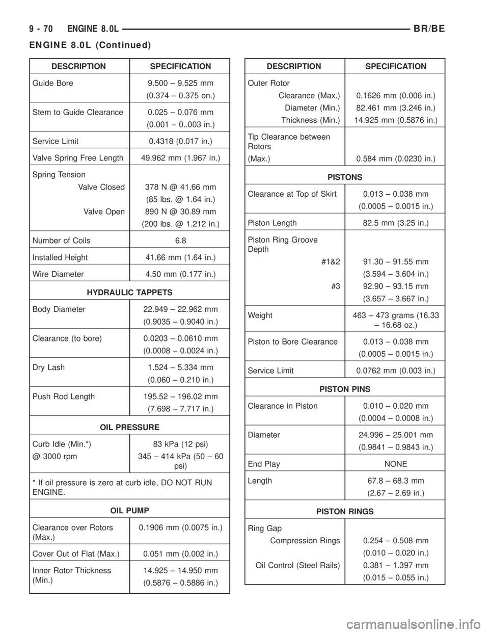
DESCRIPTION SPECIFICATION
Guide Bore 9.500 ± 9.525 mm
(0.374 ± 0.375 on.)
Stem to Guide Clearance 0.025 ± 0.076 mm
(0.001 ± 0..003 in.)
Service Limit 0.4318 (0.017 in.)
Valve Spring Free Length 49.962 mm (1.967 in.)
Spring Tension
Valve Closed 378 N @ 41.66 mm
(85 lbs. @ 1.64 in.)
Valve Open 890 N @ 30.89 mm
(200 lbs. @ 1.212 in.)
Number of Coils 6.8
Installed Height 41.66 mm (1.64 in.)
Wire Diameter 4.50 mm (0.177 in.)
HYDRAULIC TAPPETS
Body Diameter 22.949 ± 22.962 mm
(0.9035 ± 0.9040 in.)
Clearance (to bore) 0.0203 ± 0.0610 mm
(0.0008 ± 0.0024 in.)
Dry Lash 1.524 ± 5.334 mm
(0.060 ± 0.210 in.)
Push Rod Length 195.52 ± 196.02 mm
(7.698 ± 7.717 in.)
OIL PRESSURE
Curb Idle (Min.*) 83 kPa (12 psi)
@ 3000 rpm 345 ± 414 kPa (50 ± 60
psi)
* If oil pressure is zero at curb idle, DO NOT RUN
ENGINE.
OIL PUMP
Clearance over Rotors
(Max.)0.1906 mm (0.0075 in.)
Cover Out of Flat (Max.) 0.051 mm (0.002 in.)
Inner Rotor Thickness
(Min.)14.925 ± 14.950 mm
(0.5876 ± 0.5886 in.)DESCRIPTION SPECIFICATION
Outer Rotor
Clearance (Max.) 0.1626 mm (0.006 in.)
Diameter (Min.) 82.461 mm (3.246 in.)
Thickness (Min.) 14.925 mm (0.5876 in.)
Tip Clearance between
Rotors
(Max.) 0.584 mm (0.0230 in.)
PISTONS
Clearance at Top of Skirt 0.013 ± 0.038 mm
(0.0005 ± 0.0015 in.)
Piston Length 82.5 mm (3.25 in.)
Piston Ring Groove
Depth
#1&2 91.30 ± 91.55 mm
(3.594 ± 3.604 in.)
#3 92.90 ± 93.15 mm
(3.657 ± 3.667 in.)
Weight 463 ± 473 grams (16.33
± 16.68 oz.)
Piston to Bore Clearance 0.013 ± 0.038 mm
(0.0005 ± 0.0015 in.)
Service Limit 0.0762 mm (0.003 in.)
PISTON PINS
Clearance in Piston 0.010 ± 0.020 mm
(0.0004 ± 0.0008 in.)
Diameter 24.996 ± 25.001 mm
(0.9841 ± 0.9843 in.)
End Play NONE
Length 67.8 ± 68.3 mm
(2.67 ± 2.69 in.)
PISTON RINGS
Ring Gap
Compression Rings 0.254 ± 0.508 mm
(0.010 ± 0.020 in.)
Oil Control (Steel Rails) 0.381 ± 1.397 mm
(0.015 ± 0.055 in.)
9 - 70 ENGINE 8.0LBR/BE
ENGINE 8.0L (Continued)
Page 1956 of 2255
TIRES/WHEELS
TABLE OF CONTENTS
page page
TIRES/WHEELS
DIAGNOSIS AND TESTING - TIRE AND
WHEEL RUNOUT......................1
STANDARD PROCEDURE
STANDARD PROCEDURE -
TIRE ROTATION.......................2
STANDARD PROCEDURE - MATCH
MOUNTING...........................3
STANDARD PROCEDURE - TIRE AND
WHEEL BALANCE......................4
TIRES
DESCRIPTION
DESCRIPTION - SPARE TIRE - TEMPORARY...6
DESCRIPTION - TIRES..................6
DESCRIPTION - RADIAL-PLY TIRES........6
DESCRIPTION - TIRE PRESSURE FOR
HIGH SPEEDS.........................7
DESCRIPTION - REPLACEMENT TIRES.....7
DESCRIPTION - TIRE INFLATION
PRESSURES..........................7
DIAGNOSIS AND TESTING
DIAGNOSIS AND TESTING - PRESSURE
GAUGES.............................8
DIAGNOSIS AND TESTING - TREAD WEAR
INDICATORS..........................8
DIAGNOSIS AND TESTING - TIRE WEAR
PATTERNS...........................8DIAGNOSIS AND TESTING - TIRE NOISE
OR VIBRATION........................9
STANDARD PROCEDURE - REPAIRING
LEAKS...............................9
SPECIFICATIONS
TIRE REVOLUTIONS PER MILE...........9
SPARE TIRE
DESCRIPTION.........................10
WHEELS
DESCRIPTION.........................10
OPERATION...........................10
DIAGNOSIS AND TESTING
WHEEL INSPECTION..................11
STANDARD PROCEDURE - DUAL REAR
WHEEL INSTALLATION.................11
SPECIFICATIONS
TORQUE CHART......................11
STUDS
REMOVAL.............................12
INSTALLATION.........................12
WHEEL COVER
REMOVAL.............................12
INSTALLATION
INSTALLATION - REAR.................12
INSTALLATION - FRONT................12
TIRES/WHEELS
DIAGNOSIS AND TESTING - TIRE AND WHEEL
RUNOUT
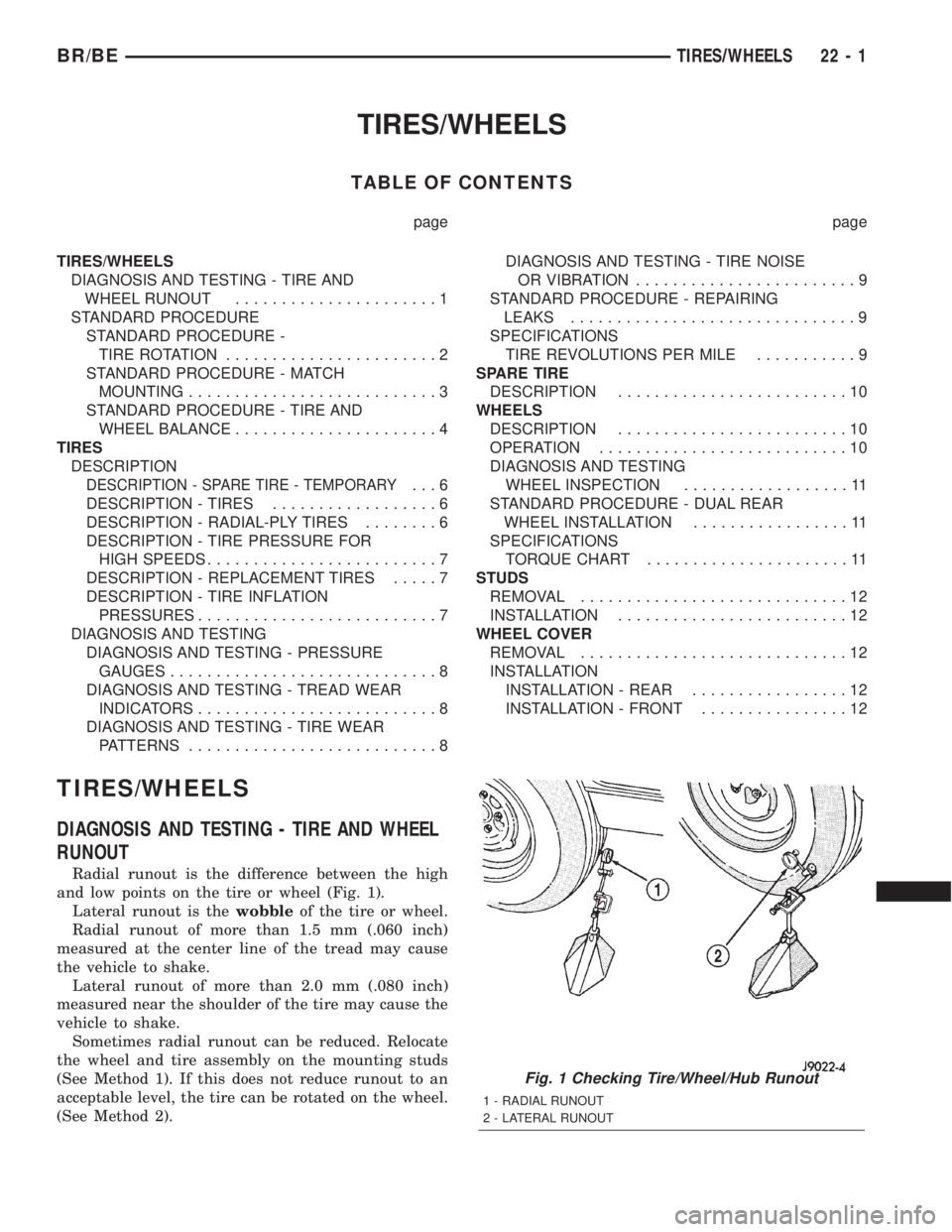
Radial runout is the difference between the high
and low points on the tire or wheel (Fig. 1).
Lateral runout is thewobbleof the tire or wheel.
Radial runout of more than 1.5 mm (.060 inch)
measured at the center line of the tread may cause
the vehicle to shake.
Lateral runout of more than 2.0 mm (.080 inch)
measured near the shoulder of the tire may cause the
vehicle to shake.
Sometimes radial runout can be reduced. Relocate
the wheel and tire assembly on the mounting studs
(See Method 1). If this does not reduce runout to an
acceptable level, the tire can be rotated on the wheel.
(See Method 2).
Fig. 1 Checking Tire/Wheel/Hub Runout
1 - RADIAL RUNOUT
2 - LATERAL RUNOUT
BR/BETIRES/WHEELS 22 - 1
Page 1957 of 2255

METHOD 1 (RELOCATE WHEEL ON HUB)
(1) Drive vehicle a short distance to eliminate tire
flat spotting from a parked position.
(2) Check wheel bearings and adjust if adjustable
or replace if necessary.
(3) Check the wheel mounting surface.
(4) Relocate wheel on the mounting, two studs
over from the original position.
(5) Tighten wheel nuts until all are properly
torqued, to eliminate brake distortion.
(6) Check radial runout. If still excessive, mark
tire sidewall, wheel, and stud at point of maximum
runout and proceed to Method 2.
METHOD 2 (RELOCATE TIRE ON WHEEL)
NOTE: Rotating the tire on wheel is particularly
effective when there is runout in both tire and
wheel.
(1) Remove tire from wheel and mount wheel on
service dynamic balance machine.
(2) Check wheel radial runout (Fig. 2) and lateral
runout (Fig. 3).
²STEEL WHEELS: Radial runout 0.040 in., Lat-
eral runout 0.045 in. (maximum)
²ALUMINUM WHEELS: Radial runout 0.030 in.,
Lateral runout 0.035 in. (maximum)
(3)
If point of greatest wheel lateral runout is near
original chalk mark, remount tire 180 degrees. Recheck
runout, Refer to match mounting procedure.
STANDARD PROCEDURE
STANDARD PROCEDURE - TIRE ROTATION
Tires on the front and rear axles operate at differ-
ent loads and perform different steering, driving, and
braking functions. For these reasons, the tires wear
at unequal rates. They may also develop irregular
wear patterns. These effects can be reduced by rotat-
ing the tires according to the maintenance schedule
in the Owners Manual. This will improve tread life,
traction and maintain a smooth quiet ride.
The recommended method of tire rotation is (Fig.
4). Other methods can be used, but may not provide
the same tire longevity benefits.
Dual wheel vehicles require a different tire rota-
tion pattern. Refer to (Fig. 5) for the proper tire rota-
tion with dual wheels.
Fig. 2 Radial Runout
1 - MOUNTING CONE
2 - SPINDLE SHAFT
3 - WING NUT
4 - PLASTIC CUP
5 - DIAL INDICATOR
6 - WHEEL
7 - DIAL INDICATOR
Fig. 3 Lateral Runout
1 - MOUNTING CONE
2 - SPINDLE SHAFT
3 - WING NUT
4 - PLASTIC CUP
5 - DIAL INDICATOR
6 - WHEEL
7 - DIAL INDICATOR
Fig. 4 Tire Rotation Pattern
22 - 2 TIRES/WHEELSBR/BE
TIRES/WHEELS (Continued)
Page 1963 of 2255
per square inch (psi) during operation. Do not reduce
this normal pressure build-up.
WARNING: OVER OR UNDER INFLATED TIRES CAN
AFFECT VEHICLE HANDLING AND TREAD WEAR.
THIS MAY CAUSE THE TIRE TO FAIL SUDDENLY,
RESULTING IN LOSS OF VEHICLE CONTROL.
DIAGNOSIS AND TESTING
DIAGNOSIS AND TESTING - PRESSURE
GAUGES
A quality air pressure gauge is recommended to
check tire pressure. After checking the air pressure,
replace valve cap finger tight.
DIAGNOSIS AND TESTING - TREAD WEAR
INDICATORS
Tread wear indicators are molded into the bottom
of the tread grooves. When tread depth is 1.6 mm
(1/16 in.), the tread wear indicators will appear as a
13 mm (1/2 in.) band (Fig. 14).
Tire replacement is necessary when indicators
appear in two or more grooves or if localized balding
occurs.
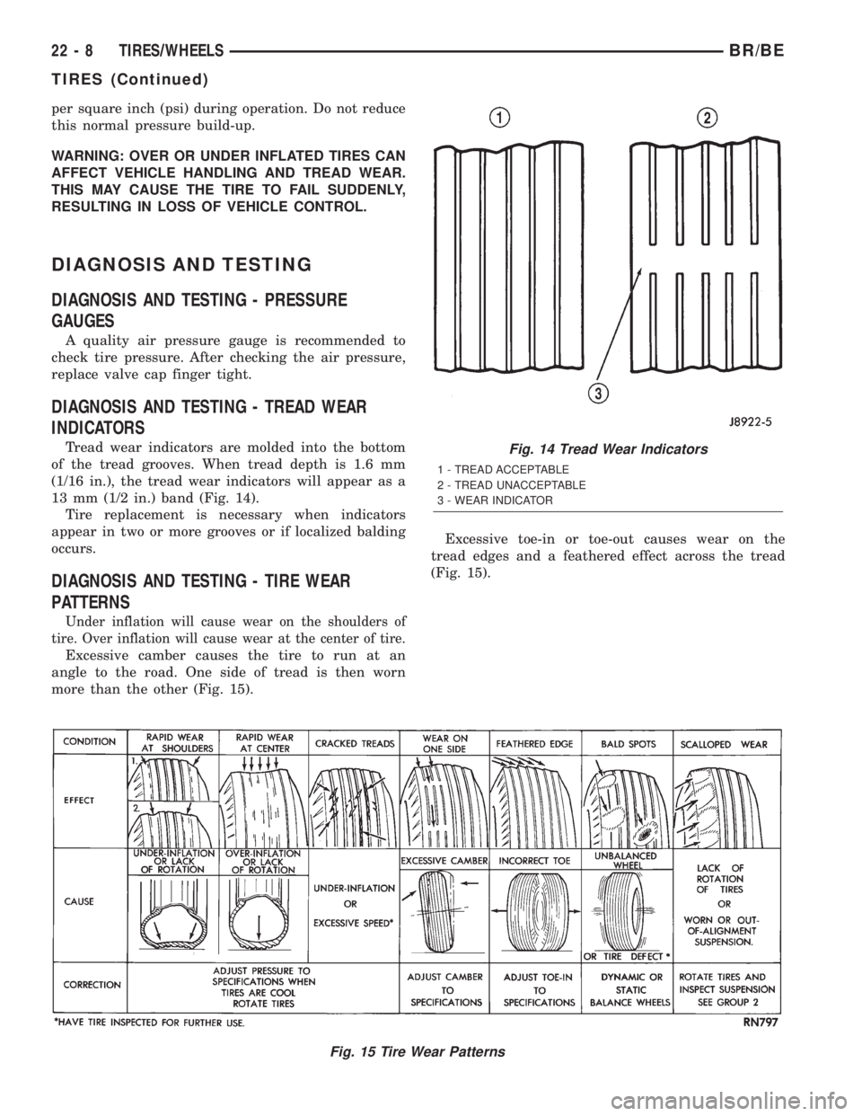
DIAGNOSIS AND TESTING - TIRE WEAR
PATTERNS
Under inflation will cause wear on the shoulders of
tire. Over inflation will cause wear at the center of tire.
Excessive camber causes the tire to run at an
angle to the road. One side of tread is then worn
more than the other (Fig. 15).Excessive toe-in or toe-out causes wear on the
tread edges and a feathered effect across the tread
(Fig. 15).
Fig. 15 Tire Wear Patterns
Fig. 14 Tread Wear Indicators
1 - TREAD ACCEPTABLE
2 - TREAD UNACCEPTABLE
3 - WEAR INDICATOR
22 - 8 TIRES/WHEELSBR/BE
TIRES (Continued)
Page 1966 of 2255
DIAGNOSIS AND TESTING
WHEEL INSPECTION
Inspect wheels for:
²Excessive run out
²Dents or cracks
²Damaged wheel lug nut holes
²Air Leaks from any area or surface of the rim
NOTE: Do not attempt to repair a wheel by hammer-
ing, heating or welding.
If a wheel is damaged an original equipment
replacement wheel should be used. When obtaining
replacement wheels, they should be equivalent in
load carrying capacity. The diameter, width, offset,
pilot hole and bolt circle of the wheel should be the
same as the original wheel.
WARNING: FAILURE TO USE EQUIVALENT REPLACE-
MENT WHEELS MAY ADVERSELY AFFECT THE
SAFETY AND HANDLING OF THE VEHICLE. USED
WHEELS ARE NOT RECOMMENDED. THE SERVICE
HISTORY OF THE WHEEL MAY HAVE INCLUDED
SEVERE TREATMENT OR VERY HIGH MILEAGE. THE
RIM COULD FAIL WITHOUT WARNING.
STANDARD PROCEDURE - DUAL REAR WHEEL
INSTALLATION
Dual rear wheels use a special heavy duty lug nut
wrench. It is recommended to remove and install dual
rear wheels only when the proper wrench is available.
The wrench is also use to remove wheel center caps for
more information refer to Owner's Manual.
The tires on both wheels must be completely raised
off the ground when tightening the lug nuts. This
will ensure correct wheel centering and maximum
wheel clamping.
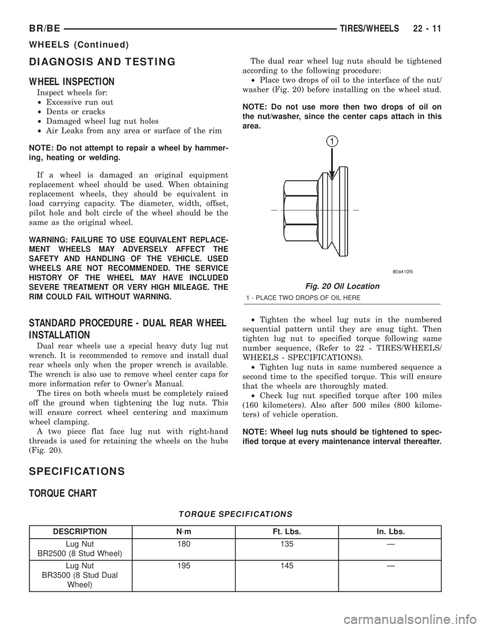
A two piece flat face lug nut with right-hand
threads is used for retaining the wheels on the hubs
(Fig. 20).The dual rear wheel lug nuts should be tightened
according to the following procedure:
²Place two drops of oil to the interface of the nut/
washer (Fig. 20) before installing on the wheel stud.
NOTE: Do not use more then two drops of oil on
the nut/washer, since the center caps attach in this
area.
²Tighten the wheel lug nuts in the numbered
sequential pattern until they are snug tight. Then
tighten lug nut to specified torque following same
number sequence, (Refer to 22 - TIRES/WHEELS/
WHEELS - SPECIFICATIONS).
²Tighten lug nuts in same numbered sequence a
second time to the specified torque. This will ensure
that the wheels are thoroughly mated.
²Check lug nut specified torque after 100 miles
(160 kilometers). Also after 500 miles (800 kilome-
ters) of vehicle operation.
NOTE: Wheel lug nuts should be tightened to spec-
ified torque at every maintenance interval thereafter.
SPECIFICATIONS
TORQUE CHART
TORQUE SPECIFICATIONS
DESCRIPTION N´m Ft. Lbs. In. Lbs.
Lug Nut
BR2500 (8 Stud Wheel)180 135 Ð
Lug Nut
BR3500 (8 Stud Dual
Wheel)195 145 Ð
Fig. 20 Oil Location
1 - PLACE TWO DROPS OF OIL HERE
BR/BETIRES/WHEELS 22 - 11
WHEELS (Continued)
Page 2234 of 2255
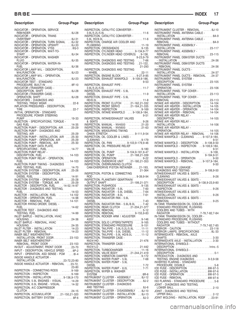
INDICATOR - OPERATION, SERVICE
REMINDER..........................8J-28
INDICATOR - OPERATION, TRANS
OVERTEMP.........................8J-31
INDICATOR - OPERATION, TURN SIGNAL . . 8J-32
INDICATOR - OPERATION, UPSHIFT......8J-33
INDICATOR - OPERATION, VTSS.........8Q-3
INDICATOR - OPERATION, WAIT-TO-
START .............................8J-34
INDICATOR - OPERATION, WASHER
FLUID..............................8J-35
INDICATOR - OPERATION, WATER-IN-
FUEL..............................8J-36
INDICATOR LAMP MIL - DESCRIPTION,
MALFUNCTION.......................8J-23
INDICATOR LAMP MIL - OPERATION,
MALFUNCTION.......................8J-23
INDICATOR TEST - STANDARD
PROCEDURE, BUILT-IN................8F-10
INDICATOR (TRANSFER CASE) -
DESCRIPTION, SHIFT.................8J-28
INDICATOR (TRANSFER CASE) -
OPERATION, SHIFT...................8J-28
INDICATORS - DIAGNOSIS AND
TESTING, TREAD WEAR................22-8
INFLATION PRESSURES - DESCRIPTION,
TIRE................................22-7
INITIAL OPERATION - STANDARD
PROCEDURE, POWER STEERING
PUMP.............................19-33
INJECTION - SPECIFICATIONS, TORQUE -
GAS FUEL..........................14-35
INJECTION PUMP - DESCRIPTION, AIR.....25-29
INJECTION PUMP - DIAGNOSIS AND
TESTING, AIR.......................25-29
INJECTION PUMP - INSTALLATION, AIR . . . 25-30
INJECTION PUMP - OPERATION, AIR.....25-29
INJECTION PUMP - REMOVAL, AIR......25-30
INJECTION PUMP DATA PLATE,
SPECIFICATIONS - FUEL...............14-77
INJECTION PUMP RELAY -
DESCRIPTION, FUEL.................14-103
INJECTION PUMP RELAY - OPERATION,
FUEL.............................14-103
INJECTION PUMP TIMING - DIAGNOSIS
AND TESTING, FUEL..................14-70
INJECTION SYSTEM - DESCRIPTION, AIR . 25-26
INJECTION SYSTEM - DESCRIPTION,
DIESEL FUEL........................14-91
INJECTION SYSTEM - OPERATION, AIR . . . 25-28
INJECTION SYSTEM - TORQUE, AIR......25-29
INJECTOR - DESCRIPTION, FUEL . . . 14-52,14-97
INJECTOR - DIAGNOSIS AND TESTING,
FUEL..............................14-53
INJECTOR - INSTALLATION, FUEL.......14-102
INJECTOR - OPERATION, FUEL..........14-98
INJECTOR - REMOVAL, FUEL..........14-101
INJECTOR FIRING ORDER, DIESEL -
FUEL..............................14-62
INJECTOR TEST - DIAGNOSIS AND
TESTING, FUEL......................14-99
INLET BAFFLE - INSTALLATION, HVAC
HOUSING...........................24-36
INLET BAFFLE - REMOVAL, HVAC
HOUSING...........................24-35
INLET FILTER - INSTALLATION..........14-23
INLET FILTER - REMOVAL..............14-23
INNER BELT WEATHERSTRIP -
INSTALLATION, FRONT DOOR..........23-153
INNER BELT WEATHERSTRIP -
REMOVAL, FRONT DOOR.............23-153
IN/OUT - ADJUSTMENT, FRONT DOOR
....23-70
INPUT - DESCRIPTION, VEHICLE SPEED
. . . 8P-2
INPUT - OPERATION, ASD SENSE - PCM
. . . 8I-4
INSIDE HANDLE ACTUATOR -
INSTALLATION
..................23-72,23-80
INSIDE HANDLE ACTUATOR - REMOVAL
. . 23-72,
23-80
INSPECTION - CONNECTING RODS
......9-169
INSPECTION - INSPECTION
.............9-169
INSPECTION - INSTALLATION
......9-136,9-170
INSPECTION, 5.9L ENGINES - VISUAL
....14-29
INSPECTION, 8.0L ENGINE - VISUAL
.....14-32
INSPECTION, A/C COMPRESSOR
CLUTCH
............................24-15
INSPECTION, ACCUMULATOR
....21-150,21-320
INSPECTION, BATTERY SYSTEM
..........8F-6INSPECTION, CATALYTIC CONVERTER -
3.9L/5.2L/5.9L........................11-6
INSPECTION, CATALYTIC CONVERTER -
5.9L HD/8.0L.........................11-6
INSPECTION, CHARGE AIR COOLER AND
PLUMBING.........................11-19
INSPECTION, CROSSHEADS............9-135
INSPECTION, CYLINDER HEAD......9-134,9-77
INSPECTION, CYLINDER HEAD COVER(S) . 9-138,
9-23,9-79
INSPECTION, DIAGNOSIS AND TESTING . . . 7-66
INSPECTION, DIAGNOSIS AND TESTING . 21-122,
21-293
INSPECTION, DIAGNOSIS AND TESTING
- WHEEL...........................22-11
INSPECTION, ENGINE BLOCK........9-27,9-85
INSPECTION, EXHAUST MANIFOLD . 9-109,9-186,
9-53
INSPECTION, EXHAUST PIPE -
3.9L/5.2L/5.9L........................11-7
INSPECTION, EXHAUST PIPE - 5.9L
DIESEL.............................11-9
INSPECTION, EXHAUST PIPE - 5.9L
HD/8.0L.............................11-8
INSPECTION, FRONT CLUTCH....21-162,21-332
INSPECTION, FRONT SERVO.....21-164,21-335
INSPECTION, INSPECTION.............9-169
INSPECTION, INTAKE MANIFOLD . . . 9-108,9-184,
9-51
INSPECTION, INTAKE/EXHAUST VALVES
& SEATS ............................9-26
INSPECTION, MANUAL - NV4500........21-20
INSPECTION, MANUAL - NV5600........21-63
INSPECTION, MEASURING TIMING
CHAIN STRETCH.................9-111,9-54
INSPECTION, OIL COOLER & LINES -
CLEANING..........................9-179
INSPECTION, OIL PAN.......9-103,9-179,9-46
INSPECTION, OIL PRESSURE RELIEF
VALVE .............................9-180
INSPECTION, OIL PUMP......9-104,9-181,9-47
INSPECTION, OIL PUMP........21-168,21-339
INSPECTION, OPERATION...............9-22
INSPECTION, OVERDRIVE UNIT . . 21-180,21-353
INSPECTION, OVERRUNNING CLUTCH
CAM/OVERDRIVE PISTON RETAINER....21-193,
21-364
INSPECTION, PISTON & CONNECTING
ROD............................9-39,9-94
INSPECTION, PLANETARY GEARTRAIN/
OUTPUT SHAFT...............21-199,21-371
INSPECTION, PUSHRODS..............9-135
INSPECTION, RADIATOR - 5.9L..........7-60
INSPECTION, RADIATOR - 5.9L DIESEL....7-64
INSPECTION, RADIATOR - 8.0L..........7-61
INSPECTION, RADIATOR FAN - 5.9L
DIESEL.............................7-43
INSPECTION, RADIATOR FAN - 5.9L/8.0L . . . 7-42
INSPECTION, REAR CLUTCH.....21-204,21-377
INSPECTION, REMOVAL................5-12
INSPECTION, REMOVAL...........9-155,9-83
INSPECTION, ROCKER ARM / ADJUSTER
ASSY..............................9-146
INSPECTION, SOLID LIFTERS/TAPPETS . . . 9-165
INSPECTION, STANDARD PROCEDURE....9-151
INSPECTION, TAILPIPE - 3.9L/5.2L/5.9L . . . 11-11
INSPECTION, TAILPIPE - 5.9L DIESEL....11-12
INSPECTION, TAILPIPE - 5.9L HD/8.0L....11-12
INSPECTION, TRANSFER CASE -
NV241HD..........................21-476
INSPECTION, TRANSFER CASE -
NV241LD..........................21-442
INSPECTION, TURBOCHARGER..........11-16
INSPECTION, VALVE BODY......21-244,21-419
INSPECTION, VIBRATION DAMPER.......9-172
INSPECTION, WATER PUMP - 5.9L........7-68
INSPECTION, WATER PUMP - 5.9L
DIESEL.............................7-72
INSPECTION, WATER PUMP - 8.0L........7-71
INSPECTION, WIPER & WASHER
SYSTEM............................8R-6
INSTRUMENT CLUSTER - ASSEMBLY.....8J-12
INSTRUMENT CLUSTER - DESCRIPTION
. . . 8J-2
INSTRUMENT CLUSTER - DIAGNOSIS
AND TESTING
........................8J-6
INSTRUMENT CLUSTER - DISASSEMBLY
. . 8J-10
INSTRUMENT CLUSTER - INSTALLATION
. . 8J-13
INSTRUMENT CLUSTER - OPERATION
.....8J-3INSTRUMENT CLUSTER - REMOVAL.....8J-10
INSTRUMENT PANEL ANTENNA CABLE -
INSTALLATION.......................8A-9
INSTRUMENT PANEL ANTENNA CABLE -
REMOVAL...........................8A-9
INSTRUMENT PANEL ASSEMBLY -
INSTALLATION......................23-117
INSTRUMENT PANEL ASSEMBLY -
REMOVAL.........................23-115
INSTRUMENT PANEL DEMISTER DUCTS
- INSTALLATION.....................24-36
INSTRUMENT PANEL DEMISTER DUCTS
- REMOVAL.........................24-36
INSTRUMENT PANEL DUCTS -
INSTALLATION.......................24-37
INSTRUMENT PANEL DUCTS - REMOVAL . 24-37
INSTRUMENT PANEL SYSTEM -
DESCRIPTION......................23-105
INSTRUMENT PANEL SYSTEM -
OPERATION........................23-106
INSTRUMENT PANEL TOP COVER -
INSTALLATION......................23-113
INSTRUMENT PANEL TOP COVER -
REMOVAL.........................23-113
INTAKE AIR HEATER - DESCRIPTION....14-104
INTAKE AIR HEATER - INSTALLATION....14-105
INTAKE AIR HEATER - OPERATION......14-104
INTAKE AIR HEATER - REMOVAL.......14-104
INTAKE AIR HEATER RELAY -
DESCRIPTION......................14-105
INTAKE AIR HEATER RELAY -
INSTALLATION.......................14-106
INTAKE AIR HEATER RELAY -
OPERATION........................14-105
INTAKE AIR HEATER RELAY - REMOVAL . 14-106
INTAKE MANIFOLD - CLEANING....9-107,9-184,
9-51
INTAKE MANIFOLD - DESCRIPTION . . 9-106,9-50
INTAKE MANIFOLD - INSPECTION . . 9-108,9-184,
9-51
INTAKE MANIFOLD - INSTALLATION.....9-108,
9-184,9-51
INTAKE MANIFOLD - OPERATION.........9-50
INTAKE MANIFOLD - REMOVAL....9-107,9-184,
9-50
INTAKE MANIFOLD LEAKAGE -
DIAGNOSIS AND TESTING.........9-106,9-50
INTAKE/EXHAUST VALVES & SEATS -
CLEANING...........................9-26
INTAKE/EXHAUST VALVES & SEATS -
DESCRIPTION...............9-138,9-23,9-80
INTAKE/EXHAUST VALVES & SEATS -
INSPECTION.........................9-26
INTAKE/EXHAUST VALVES & SEATS -
INSTALLATION........................9-26
INTAKE/EXHAUST VALVES & SEATS -
REMOVAL...........................9-25
IN-TANK TRANSMISSION OIL COOLER -
STANDARD PROCEDURE, FLUSHING
COOLERS AND TUBES - WITH
RADIATOR...................7-78,7-82,7-84
IN-TANK TRANSMISSION OIL COOLER -
STANDARD PROCEDURE, FLUSHING
COOLERS AND TUBES - WITHOUT
RADIATOR...................7-79,7-82,7-85
INTERIOR - CAUTION................23-118
INTERIOR LAMPS, SPECIFICATIONS......8L-33
INTERMEDIATE - REMOVAL, AXLE
SHAFTS.............................3-30
INTERMEDIATE AXLE - INSTALLATION.....3-30
INTERNATIONAL SYMBOLS -
DESCRIPTION......................Intro.-5
INTERNATIONAL SYMBOLS -
DESCRIPTION.........................0-1
INTRODUCTION - DIAGNOSIS AND
TESTING, ENGINE DIAGNOSIS........9-3,9-58
INVERTED FLARING - STANDARD
PROCEDURE, DOUBLE..................5-8
IOD FUSE - DESCRIPTION...........8W-97-5
IOD FUSE - INSTALLATION...........8W-97-6
IOD FUSE - OPERATION.............8W-97-5
IOD FUSE - REMOVAL
..............8W-97-6
ISO FLARING - STANDARD PROCEDURE
....5-8
JOINT - DIAGNOSIS AND TESTING,
LOWER BALL
........................2-10
JOINT - DIAGNOSIS AND TESTING,
UPPER BALL
.........................2-12
JOINT MOLDING - INSTALLATION, ROOF
. . 23-91
BR/BEINDEX 17
Description Group-Page Description Group-Page Description Group-Page