service interval DODGE RAM 2002 Service Repair Manual
[x] Cancel search | Manufacturer: DODGE, Model Year: 2002, Model line: RAM, Model: DODGE RAM 2002Pages: 2255, PDF Size: 62.07 MB
Page 19 of 2255
DESCRIPTION - AUTOMATIC TRANSMISSION
FLUID
NOTE: Refer to the maintenance schedules in this
group for the recommended maintenance (fluid/filter
change) intervals for this transmission.
NOTE: Refer to Service Procedures in this group for
fluid level checking procedures.
MopartATF +4, type 9602, Automatic Transmis-
sion Fluid is the recommended fluid for
DaimlerChrysler automatic transmissions.
Dexron II fluid IS NOT recommended. Clutch
chatter can result from the use of improper
fluid.
MopartATF +4, type 9602, Automatic Transmis-
sion Fluid when new is red in color. The ATF is dyed
red so it can be identified from other fluids used in
the vehicle such as engine oil or antifreeze. The red
color is not permanent and is not an indicator of fluid
condition. As the vehicle is driven, the ATF will begin
to look darker in color and may eventually become
brown.This is normal.A dark brown/black fluid
accompanied with a burnt odor and/or deterioration
in shift quality may indicate fluid deterioration or
transmission component failure.
FLUID ADDITIVES
DaimlerChrysler strongly recommends against the
addition of any fluids to the transmission, other than
those automatic transmission fluids listed above.
Exceptions to this policy are the use of special dyes
to aid in detecting fluid leaks.
Various ªspecialº additives and supplements exist
that claim to improve shift feel and/or quality. These
additives and others also claim to improve converter
clutch operation and inhibit overheating, oxidation,
varnish, and sludge. These claims have not been sup-
ported to the satisfaction of DaimlerChrysler and
these additivesmust not be used.The use of trans-
mission ªsealersº should also be avoided, since they
may adversely affect the integrity of transmission
seals.
OPERATION - AUTOMATIC TRANSMISSION
FLUID
The automatic transmission fluid is selected based
upon several qualities. The fluid must provide a high
level of protection for the internal components by
providing a lubricating film between adjacent metal
components. The fluid must also be thermally stable
so that it can maintain a consistent viscosity through
a large temperature range. If the viscosity stays con-
stant through the temperature range of operation,transmission operation and shift feel will remain con-
sistent. Transmission fluid must also be a good con-
ductor of heat. The fluid must absorb heat from the
internal transmission components and transfer that
heat to the transmission case.
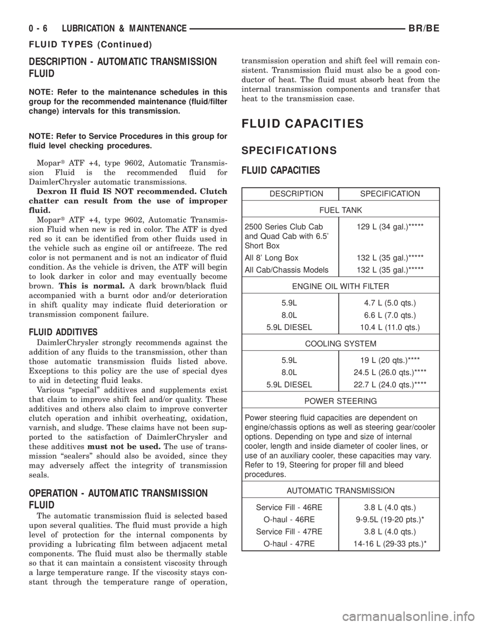
FLUID CAPACITIES
SPECIFICATIONS
FLUID CAPACITIES
DESCRIPTION SPECIFICATION
FUEL TANK
2500 Series Club Cab
and Quad Cab with 6.5'
Short Box129 L (34 gal.)*****
All 8' Long Box 132 L (35 gal.)*****
All Cab/Chassis Models 132 L (35 gal.)*****
ENGINE OIL WITH FILTER
5.9L 4.7 L (5.0 qts.)
8.0L 6.6 L (7.0 qts.)
5.9L DIESEL 10.4 L (11.0 qts.)
COOLING SYSTEM
5.9L 19 L (20 qts.)****
8.0L 24.5 L (26.0 qts.)****
5.9L DIESEL 22.7 L (24.0 qts.)****
POWER STEERING
Power steering fluid capacities are dependent on
engine/chassis options as well as steering gear/cooler
options. Depending on type and size of internal
cooler, length and inside diameter of cooler lines, or
use of an auxiliary cooler, these capacities may vary.
Refer to 19, Steering for proper fill and bleed
procedures.
AUTOMATIC TRANSMISSION
Service Fill - 46RE 3.8 L (4.0 qts.)
O-haul - 46RE 9-9.5L (19-20 pts.)*
Service Fill - 47RE 3.8 L (4.0 qts.)
O-haul - 47RE 14-16 L (29-33 pts.)*
0 - 6 LUBRICATION & MAINTENANCEBR/BE
FLUID TYPES (Continued)
Page 403 of 2255
Excessive IOD can be caused by:
²Electrical items left on.
²Faulty or improperly adjusted switches.
²Faulty or shorted electronic modules and compo-
nents.
²An internally shorted generator.
²Intermittent shorts in the wiring.
If the IOD is over thirty-five milliamperes, the
problem must be found and corrected before replac-
ing a battery. In most cases, the battery can becharged and returned to service after the excessive
IOD condition has been corrected.
(1) Verify that all electrical accessories are off.
Turn off all lamps, remove the ignition key, and close
all doors. If the vehicle is equipped with an illumi-
nated entry system or an electronically tuned radio,
allow the electronic timer function of these systems
to automatically shut off (time out). This may take
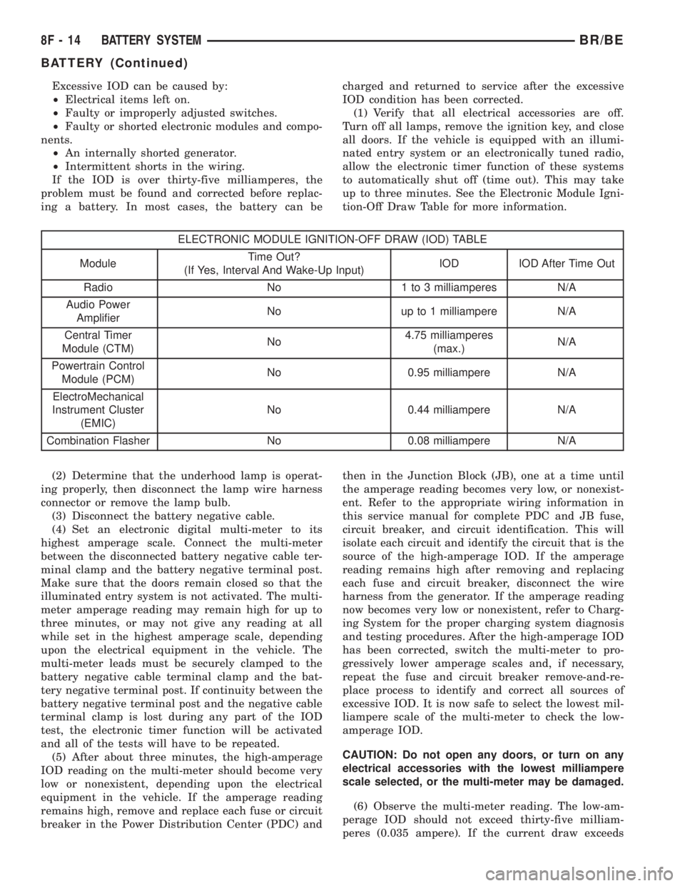
up to three minutes. See the Electronic Module Igni-
tion-Off Draw Table for more information.
ELECTRONIC MODULE IGNITION-OFF DRAW (IOD) TABLE
ModuleTime Out?
(If Yes, Interval And Wake-Up Input)IOD IOD After Time Out
Radio No 1 to 3 milliamperes N/A
Audio Power
AmplifierNo up to 1 milliampere N/A
Central Timer
Module (CTM)No4.75 milliamperes
(max.)N/A
Powertrain Control
Module (PCM)No 0.95 milliampere N/A
ElectroMechanical
Instrument Cluster
(EMIC)No 0.44 milliampere N/A
Combination Flasher No 0.08 milliampere N/A
(2) Determine that the underhood lamp is operat-
ing properly, then disconnect the lamp wire harness
connector or remove the lamp bulb.
(3) Disconnect the battery negative cable.
(4) Set an electronic digital multi-meter to its
highest amperage scale. Connect the multi-meter
between the disconnected battery negative cable ter-
minal clamp and the battery negative terminal post.
Make sure that the doors remain closed so that the
illuminated entry system is not activated. The multi-
meter amperage reading may remain high for up to
three minutes, or may not give any reading at all
while set in the highest amperage scale, depending
upon the electrical equipment in the vehicle. The
multi-meter leads must be securely clamped to the
battery negative cable terminal clamp and the bat-
tery negative terminal post. If continuity between the
battery negative terminal post and the negative cable
terminal clamp is lost during any part of the IOD
test, the electronic timer function will be activated
and all of the tests will have to be repeated.
(5) After about three minutes, the high-amperage
IOD reading on the multi-meter should become very
low or nonexistent, depending upon the electrical
equipment in the vehicle. If the amperage reading
remains high, remove and replace each fuse or circuit
breaker in the Power Distribution Center (PDC) andthen in the Junction Block (JB), one at a time until
the amperage reading becomes very low, or nonexist-
ent. Refer to the appropriate wiring information in
this service manual for complete PDC and JB fuse,
circuit breaker, and circuit identification. This will
isolate each circuit and identify the circuit that is the
source of the high-amperage IOD. If the amperage
reading remains high after removing and replacing
each fuse and circuit breaker, disconnect the wire
harness from the generator. If the amperage reading
now becomes very low or nonexistent, refer to Charg-
ing System for the proper charging system diagnosis
and testing procedures. After the high-amperage IOD
has been corrected, switch the multi-meter to pro-
gressively lower amperage scales and, if necessary,
repeat the fuse and circuit breaker remove-and-re-
place process to identify and correct all sources of
excessive IOD. It is now safe to select the lowest mil-
liampere scale of the multi-meter to check the low-
amperage IOD.
CAUTION: Do not open any doors, or turn on any
electrical accessories with the lowest milliampere
scale selected, or the multi-meter may be damaged.
(6) Observe the multi-meter reading. The low-am-
perage IOD should not exceed thirty-five milliam-
peres (0.035 ampere). If the current draw exceeds
8F - 14 BATTERY SYSTEMBR/BE
BATTERY (Continued)
Page 433 of 2255
OPERATION - HEATED MIRROR SYSTEM
The solid state electronic control logic and timer
circuitry for the heated mirror system receives bat-
tery current from a fuse in the Junction Block (JB)
only when the ignition switch is in the On or Start
positions. After the heated mirror system is turned
On, the electronic control logic and timer circuitry
will automatically turn the system off after a pro-
grammed time interval of about fifteen minutes.
After the initial time interval has expired, if the
heated mirror switch is depressed and released a sec-
ond time during the same ignition cycle, the elec-
tronic control logic and timer circuitry will
automatically turn the heated mirror system off after
a programmed time interval of about five minutes.
The heated mirror system will be shut off automati-
cally if the ignition switch is turned to the Off or
Accessory positions. After the heated mirror system
is turned On, it can also be turned off manually by
depressing and releasing the heated mirror switch a
second time.
When the heated mirror system is turned On, the
heated mirror system control logic and timer cir-
cuitry energizes the heated mirror system indicator
lamp and the heated mirror relay. When energized,
the heated mirror relay supplies fused ignition
switch output (run/start) current from a fuse in the
JB to the outside mirror heating grids located behind
the mirror glass of each of the outside rear view mir-
rors. When energized, each of the outside mirror
heating grids produces enough heat to warm the
glass of the outside rear view mirrors.
DIAGNOSIS AND TESTING - HEATED MIRROR
SYSTEM
If only one of the outside mirror heating grids is
inoperative, perform continuity checks on the circuits
and heater grid for that mirror only. If both outside
mirror heating grids are inoperative, proceed with
the heated mirror system diagnosis as follows. (Refer
to Appropriate Wiring Information).
WARNING: ON VEHICLES EQUIPPED WITH AIR-
BAGS, DISABLE THE AIRBAG SYSTEM BEFORE
ATTEMPTING ANY STEERING WHEEL, STEERING
COLUMN, OR INSTRUMENT PANEL COMPONENT
DIAGNOSIS OR SERVICE. DISCONNECT AND ISO-
LATE THE BATTERY NEGATIVE (GROUND) CABLE,
THEN WAIT TWO MINUTES FOR THE AIRBAG SYS-
TEM CAPACITOR TO DISCHARGE BEFORE PER-
FORMING FURTHER DIAGNOSIS OR SERVICE. THIS
IS THE ONLY SURE WAY TO DISABLE THE AIRBAG
SYSTEM. FAILURE TO TAKE THE PROPER PRE-
CAUTIONS COULD RESULT IN ACCIDENTAL AIR-
BAG DEPLOYMENT AND POSSIBLE PERSONAL
INJURY.The operation of the heated mirror system can be
confirmed in one of the following manners:
²Turn the ignition switch to the On position.
While monitoring the instrument panel voltmeter,
momentarily depress and release the heated mirror
switch. When the heated mirror system is turned On,
a distinct voltmeter needle deflection should be
noted.
²Turn the ignition switch to the On position.
Momentarily depress and release the heated mirror
switch to turn the heated mirror system On. The
heated mirror operation can be checked by feeling
the outside rear view mirror glass. A distinct differ-
ence in temperature between the unheated and
heated mirror glass can be detected within three to
four minutes of system operation.
The above checks will confirm system operation.
Illumination of the heated mirror system indicator
lamp means that there is electrical current available
at the heated mirror relay, but does not confirm that
the electrical current is reaching the outside mirror
heating grids.
If the heated mirror system does not operate, the
problem should be isolated in the following manner:
(1) Confirm that the ignition switch is in the On
position.
(2) Check the fuses in the Power Distribution Cen-
ter (PDC) and in the Junction Block (JB). The fuses
must be tight in their receptacles and all electrical
connections must be secure.
When the above steps have been completed and
both outside mirror heating grids are still inopera-
tive, one or more of the following is faulty:
²Heated mirror switch, electronic control logic
and timer circuitry, and heated mirror relay.
²Heated mirror wire harness circuits or connec-
tors.
²Outside mirror heating grid (both mirror grids
would have to be faulty).
If turning On the heated mirror system produces a
severe voltmeter deflection or fuse failures, check for
a shorted circuit between the output of the heated
mirror relay and the outside mirror heating grids.
MIRROR SWITCH
DESCRIPTION
The heated mirror switch, the heated mirror sys-
tem indicator lamp, the heated mirror system solid
state electronic control logic and timer circuitry and
the heated mirror relay are all integral to the a/c
heater control, which is located between the instru-
ment cluster and the radio near the center of the
instrument cluster bezel on the instrument panel.
The heated mirror switch and the heated mirror sys-
8G - 2 HEATED MIRRORSBR/BE
HEATED MIRRORS (Continued)
Page 434 of 2255
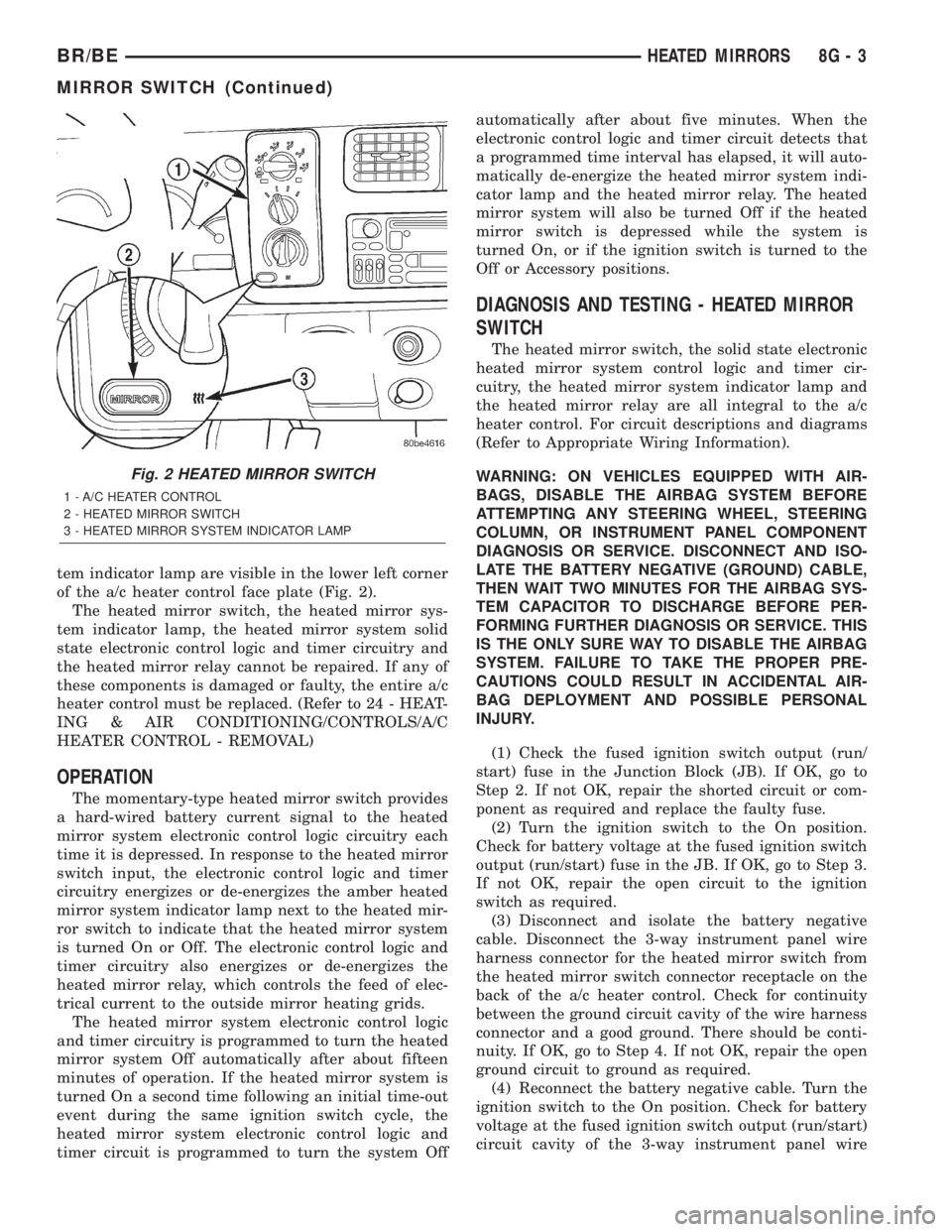
tem indicator lamp are visible in the lower left corner
of the a/c heater control face plate (Fig. 2).
The heated mirror switch, the heated mirror sys-
tem indicator lamp, the heated mirror system solid
state electronic control logic and timer circuitry and
the heated mirror relay cannot be repaired. If any of
these components is damaged or faulty, the entire a/c
heater control must be replaced. (Refer to 24 - HEAT-
ING & AIR CONDITIONING/CONTROLS/A/C
HEATER CONTROL - REMOVAL)
OPERATION
The momentary-type heated mirror switch provides
a hard-wired battery current signal to the heated
mirror system electronic control logic circuitry each
time it is depressed. In response to the heated mirror
switch input, the electronic control logic and timer
circuitry energizes or de-energizes the amber heated
mirror system indicator lamp next to the heated mir-
ror switch to indicate that the heated mirror system
is turned On or Off. The electronic control logic and
timer circuitry also energizes or de-energizes the
heated mirror relay, which controls the feed of elec-
trical current to the outside mirror heating grids.
The heated mirror system electronic control logic
and timer circuitry is programmed to turn the heated
mirror system Off automatically after about fifteen
minutes of operation. If the heated mirror system is
turned On a second time following an initial time-out
event during the same ignition switch cycle, the
heated mirror system electronic control logic and
timer circuit is programmed to turn the system Offautomatically after about five minutes. When the
electronic control logic and timer circuit detects that
a programmed time interval has elapsed, it will auto-
matically de-energize the heated mirror system indi-
cator lamp and the heated mirror relay. The heated
mirror system will also be turned Off if the heated
mirror switch is depressed while the system is
turned On, or if the ignition switch is turned to the
Off or Accessory positions.
DIAGNOSIS AND TESTING - HEATED MIRROR
SWITCH
The heated mirror switch, the solid state electronic
heated mirror system control logic and timer cir-
cuitry, the heated mirror system indicator lamp and
the heated mirror relay are all integral to the a/c
heater control. For circuit descriptions and diagrams
(Refer to Appropriate Wiring Information).
WARNING: ON VEHICLES EQUIPPED WITH AIR-
BAGS, DISABLE THE AIRBAG SYSTEM BEFORE
ATTEMPTING ANY STEERING WHEEL, STEERING
COLUMN, OR INSTRUMENT PANEL COMPONENT
DIAGNOSIS OR SERVICE. DISCONNECT AND ISO-
LATE THE BATTERY NEGATIVE (GROUND) CABLE,
THEN WAIT TWO MINUTES FOR THE AIRBAG SYS-
TEM CAPACITOR TO DISCHARGE BEFORE PER-
FORMING FURTHER DIAGNOSIS OR SERVICE. THIS
IS THE ONLY SURE WAY TO DISABLE THE AIRBAG
SYSTEM. FAILURE TO TAKE THE PROPER PRE-
CAUTIONS COULD RESULT IN ACCIDENTAL AIR-
BAG DEPLOYMENT AND POSSIBLE PERSONAL
INJURY.
(1) Check the fused ignition switch output (run/
start) fuse in the Junction Block (JB). If OK, go to
Step 2. If not OK, repair the shorted circuit or com-
ponent as required and replace the faulty fuse.
(2) Turn the ignition switch to the On position.
Check for battery voltage at the fused ignition switch
output (run/start) fuse in the JB. If OK, go to Step 3.
If not OK, repair the open circuit to the ignition
switch as required.
(3) Disconnect and isolate the battery negative
cable. Disconnect the 3-way instrument panel wire
harness connector for the heated mirror switch from
the heated mirror switch connector receptacle on the
back of the a/c heater control. Check for continuity
between the ground circuit cavity of the wire harness
connector and a good ground. There should be conti-
nuity. If OK, go to Step 4. If not OK, repair the open
ground circuit to ground as required.
(4) Reconnect the battery negative cable. Turn the
ignition switch to the On position. Check for battery
voltage at the fused ignition switch output (run/start)
circuit cavity of the 3-way instrument panel wire
Fig. 2 HEATED MIRROR SWITCH
1 - A/C HEATER CONTROL
2 - HEATED MIRROR SWITCH
3 - HEATED MIRROR SYSTEM INDICATOR LAMP
BR/BEHEATED MIRRORS 8G - 3
MIRROR SWITCH (Continued)
Page 507 of 2255
overlay causes the ªMAINT REQDº text to appear in
amber through the translucent outer layer of the
overlay when the indicator is illuminated from
behind by a Light Emitting Diode (LED) soldered
onto the instrument cluster electronic circuit board.
The SRI is serviced as a unit with the instrument
cluster.
OPERATION
The Service Reminder Indicator (SRI) gives an
indication to the vehicle operator when engine emis-
sions maintenance procedures should be performed.
This indicator is controlled by a transistor on the
instrument cluster circuit board based upon the clus-
ter programming and electronic messages received by
the cluster from the Powertrain Control Module
(PCM) over the Chrysler Collision Detection (CCD)
data bus. The SRI Light Emitting Diode (LED)
receives battery current on the instrument cluster
electronic circuit board through the fused ignition
switch output (st-run) circuit whenever the ignition
switch is in the On or Start positions; therefore, the
LED will always be off when the ignition switch is in
any position except On or Start. The LED only illu-
minates when it is provided a path to ground by the
instrument cluster transistor. The instrument cluster
will turn on the SRI for the following reasons:
²Bulb Test- Each time the ignition switch is
turned to the On position the SRI is illuminated for
about two seconds as a bulb test.
²Service Required Lamp-On Message- Each
time the cluster receives a service required lamp-on
message from the PCM indicating that an emissions
maintenance interval has been reached, the SRI will
be illuminated. The indicator remains illuminated
until the cluster receives a service required lamp-off
message from the PCM, or until the ignition switch
is turned to the Off position, whichever occurs first.
²Actuator Test- Each time the cluster is put
through the actuator test, the SRI will be turned on
during the bulb check portion of the test to confirm
the functionality of the LED and the cluster control
circuitry.
The PCM continually monitors the vehicle speed
sensor to determine the distance the vehicle has been
driven, then sends the proper messages to the instru-
ment cluster. Once the SRI has been illuminated and
the required emissions maintenance procedures have
been completed, the PCM must be reset using a
DRBIIItscan tool before it will send the proper ser-
vice required lamp-off message to the instrument
cluster. Refer to the appropriate diagnostic informa-
tion. For further diagnosis of the SRI or the instru-
ment cluster circuitry that controls the LED, (Refer
to 8 - ELECTRICAL/INSTRUMENT CLUSTER -
DIAGNOSIS AND TESTING). For proper diagnosisof the PCM, the CCD data bus, or the message
inputs to the instrument cluster that control the SRI,
a DRBIIItscan tool is required. Refer to the appro-
priate diagnostic information.
SHIFT INDICATOR (TRANSFER
CASE)
DESCRIPTION
A four-wheel drive indicator is standard equipment
on all instrument clusters. However, on vehicles not
equipped with the optional four-wheel drive system,
this indicator is mechanically disabled. The four-
wheel drive indicator is located near the lower edge
of the instrument cluster overlay, to the right of cen-
ter. The four-wheel drive indicator consists of a sten-
cilled cutout of the text ª4WDº in the opaque layer of
the instrument cluster overlay. The dark outer layer
of the overlay prevents the indicator from being
clearly visible when it is not illuminated. An amber
lens behind the cutout in the opaque layer of the
overlay causes the ª4WDº text to appear in amber
through the translucent outer layer of the overlay
when the indicator is illuminated from behind by a
Light Emitting Diode (LED) soldered onto the instru-
ment cluster electronic circuit board. The four-wheel
drive indicator is serviced as a unit with the instru-
ment cluster.
OPERATION
The four-wheel drive indicator lamp gives an indi-
cation to the vehicle operator that a four-wheel drive
operating mode is engaged. The indicator will be illu-
minated when either high range (4H) or low range
(4L) have been selected with the transfer case shift
lever. This indicator is controlled by a transistor on
the instrument cluster circuit board based upon the
cluster programming, and a hard wired input from
the four-wheel drive switch on the front axle discon-
nect housing. The four-wheel drive indicator Light
Emitting Diode (LED) receives battery current on the
instrument cluster electronic circuit board through
the fused ignition switch output (st-run) circuit
whenever the ignition switch is in the On or Start
positions; therefore, the lamp will always be off when
the ignition switch is in any position except On or
Start. The LED only illuminates when it is switched
to ground by the instrument cluster transistor.
The four-wheel drive switch is connected in series
between ground and the four-wheel drive switch
sense input to the instrument cluster. For further
information on the transfer case and the transfer
case operating ranges, (Refer to 21 - TRANSMIS-
SION/TRANSAXLE/TRANSFER CASE - OPERA-
TION. For further information on the front axle
8J - 28 INSTRUMENT CLUSTERBR/BE
SERVICE REMINDER INDICATOR (Continued)
Page 540 of 2255
²Turn Signal Control- The multi-function
switch control stalk actuates the turn signal switch.
When the control stalk is moved in the upward direc-
tion, the right turn signal circuitry is activated; and,
when the control stalk is moved in the downward
direction, the left turn signal circuitry is activated.
The multi-function switch turn signal circuitry simul-
taneously provides a signal to the turn signal sense
of the combination flasher to activate or deactivate
the flasher output, and directs the output of the
flasher to the proper turn signal lamps. The turn sig-
nal switch has a detent position in each direction
that provides turn signals with automatic cancella-
tion, and an intermediate, momentary position in
each direction that provides turn signals only until
the multi-function switch control stalk is released.
When the control stalk is moved to a turn signal
switch detent position, the cancel actuator extends
toward the center of the steering column. A turn sig-
nal cancel cam that is integral to the clockspring
mechanism rotates with the steering wheel and the
cam lobes contact the cancel actuator when it is
extended from the multi-function switch. When the
steering wheel is rotated during a turning maneuver,
one of the two turn signal cancel cam lobes will con-
tact the turn signal cancel actuator. The cancel
actuator latches against the cancel cam rotation in
the direction opposite that which is signaled. In other
words, if the left turn signal detent is selected, the
lobes of the cancel cam will ratchet past the cancel
actuator when the steering wheel is rotated to the
left, but will unlatch the cancel actuator as the steer-
ing wheel rotates to the right and returns to center,
which will cancel the turn signal event and release
the control stalk from the detent so it returns to the
neutral Off position.
²Washer Mode- Pushing the button on the end
of the multi-function switch control knob towards the
steering column provides a battery current output
through the momentary single pole, single throw
washer switch circuitry to operate the washer pump/
motor and provides a signal to the CTM. If the wip-
ers are not operating when the washer switch is
actuated, the CTM will operate the wiper motor for
as long as the washer switch is depressed plus about
three additional wipe cycles. If the wipers are oper-
ating in the intermittent mode when the washer
switch is actuated, the CTM will operate the wiper
motor at a fixed low speed for as long as the washer
switch is depressed plus about three additional wipe
cycles before the wipers return to the selected inter-
mittent wipe interval.DIAGNOSIS AND TESTING - MULTI-FUNCTION
SWITCH
Refer to the appropriate wiring information. The
wiring information includes wiring diagrams, proper
wire and connector repair procedures, details of wire
harness routing and retention, connector pin-out
information and location views for the various wire
harness connectors, splices and grounds.
WARNING: ON VEHICLES EQUIPPED WITH AIR-
BAGS, DISABLE THE AIRBAG SYSTEM BEFORE
ATTEMPTING ANY STEERING WHEEL, STEERING
COLUMN, OR INSTRUMENT PANEL COMPONENT
DIAGNOSIS OR SERVICE. DISCONNECT AND ISO-
LATE THE BATTERY NEGATIVE (GROUND) CABLE,
THEN WAIT TWO MINUTES FOR THE AIRBAG SYS-
TEM CAPACITOR TO DISCHARGE BEFORE PER-
FORMING FURTHER DIAGNOSIS OR SERVICE. THIS
IS THE ONLY SURE WAY TO DISABLE THE AIRBAG
SYSTEM. FAILURE TO TAKE THE PROPER PRE-
CAUTIONS COULD RESULT IN ACCIDENTAL AIR-
BAG DEPLOYMENT AND POSSIBLE PERSONAL
INJURY.
(1) Disconnect and isolate the battery negative
cable. Disconnect the instrument panel wire harness
connector from the multi-function switch connector
receptacle.
(2) Using an ohmmeter, perform the continuity
and resistance tests at the terminals in the multi-
function switch connector receptacle as shown in the
Multi-Function Switch Tests chart (Fig. 25).
BR/BELAMPS/LIGHTING - EXTERIOR 8L - 25
MULTI-FUNCTION SWITCH (Continued)
Page 557 of 2255
using the U.S./Metric push button. The displayed
temperature is not an instant reading of conditions,
but an average temperature. It may take the ther-
mometer display several minutes to respond to a
major temperature change, such as driving out of a
heated garage into winter temperatures.
When the ignition switch is turned to the Off posi-
tion, the last displayed temperature reading stays in
the thermometer unit memory. When the ignition
switch is turned to the On position again, the ther-
mometer will display the memory temperature if the
engine coolant temperature is above about 43É C
(109É F). If the engine coolant temperature is below
about 43É C (109É F), the thermometer will display
the actual temperature sensed by the ambient tem-
perature sensor. The thermometer temperature dis-
play update interval varies with the vehicle speed;
therefore, if the temperature reading seems inaccu-
rate, drive the vehicle for at least three minutes
while maintaining a speed of 48 kilometers-per-hour
(30 miles-per-hour) or higher.
The thermometer function is supported by an
ambient temperature sensor. The sensor is mounted
outside the passenger compartment near the front
and center of the vehicle, and is hard wired to the
module. The ambient temperature sensor is available
as a separate service item.
STANDARD PROCEDURE
STANDARD PROCEDURE - COMPASS
CALIBRATION
CAUTION: Do not place any external magnets, such
as magnetic roof mount antennas, in the vicinity of
the compass. Do not use magnetic tools when ser-
vicing the overhead console.
The electronic compass unit features a self-cali-
brating design, which simplifies the calibration pro-
cedure. This feature automatically updates the
compass calibration while the vehicle is being driven.
This allows the compass unit to compensate for small
changes in the residual magnetism that the vehicle
may acquire during normal use. If the compass read-
ings appear to be erratic or out of calibration, per-
form the following calibration procedure. Also, new
service replacement compass mini-trip computer
modules must have their compass calibrated using
this procedure. Do not attempt to calibrate the com-
pass near large metal objects such as other vehicles,
large buildings, or bridges; or, near overhead or
underground power lines.
(1) Start the engine. If the compass/temperature
data is not currently being displayed, momentarily
depress and release the Step push button to stepthrough the display options until you have reached
the compass/temperature display.
(2) Depress both the U.S./Metric and the Step
push buttons at the same time for more than six sec-
onds, until ªCALº appears in the display, then release
both push buttons. The ªCALº in the display indi-
cates that the compass is in the calibration mode.
(3) Drive the vehicle on a level surface, at least
fifty feet away from large metal objects and power
lines, in all four compass directions, such as driving
around a city block several times or driving in two to
three complete circles at a slow to medium speed.
(4) When the calibration is successfully completed,
ªCALº will disappear from the display and normal
compass mini-trip computer operation will resume.
NOTE: If the ªCALº message remains in the display,
either there is excessive magnetism near the com-
pass, or the unit is faulty. Repeat the calibration
procedure at least one more time.
NOTE: If the wrong direction is still indicated in the
compass display, the area selected for calibration
may be too close to a strong magnetic field. Repeat
the calibration procedure in another location.
STANDARD PROCEDURE - COMPASS
VARIATION ADJUSTMENT
Compass variance, also known as magnetic decli-
nation, is the difference in angle between magnetic
north and true geographic north. In some geographic
locations, the difference between magnetic and geo-
graphic north is great enough to cause the compass
to give false readings. If this problem occurs, the
compass variance must be set. There are two meth-
ods that can be used to enter this information into
the compass mini-trip computer module. They are
the zone method and the direct method.
ZONE METHOD
(1) Using the Variance Settings map, find your
geographic location and note the zone number (Fig.
2).
(2) Turn the ignition switch to the On position. If
the compass/temperature data is not currently being
displayed, momentarily depress and release the Step
push button to step through the display options until
you have reached the compass/temperature display.
(3) Depress both the U.S./Metric and the Step
push buttons at the same time and hold them down
for more than 100 milliseconds, but not more than
one second. The compass mini-trip computer will
enter the variation adjustment mode and ªVARº
along with the current variance zone will appear in
the display.
8M - 4 MESSAGE SYSTEMSBR/BE
OVERHEAD CONSOLE (Continued)
Page 1065 of 2255
If a vehicle will be stored for more than about thirty
days, the battery negative cable should be discon-
nected to eliminate normal IOD; and, the battery
should be tested and recharged at regular intervals
during the vehicle storage period to prevent the bat-
tery from becoming discharged or damaged. Refer to
theBatterysection of the service manual for the
location of additional service information covering
the battery.
REMOVAL
The Ignition-Off Draw (IOD) fuse is disconnected
from Junction Block (JB) fuse cavity 12 when the
vehicle is shipped from the assembly plant. Dealer
personnel must reconnect the IOD fuse when the
vehicle is being prepared for delivery in order to
restore full electrical system operation.
(1) Turn the ignition switch to the Off position.
(2) Remove the fuse access panel by unsnapping it
from the left outboard end of the instrument panel.
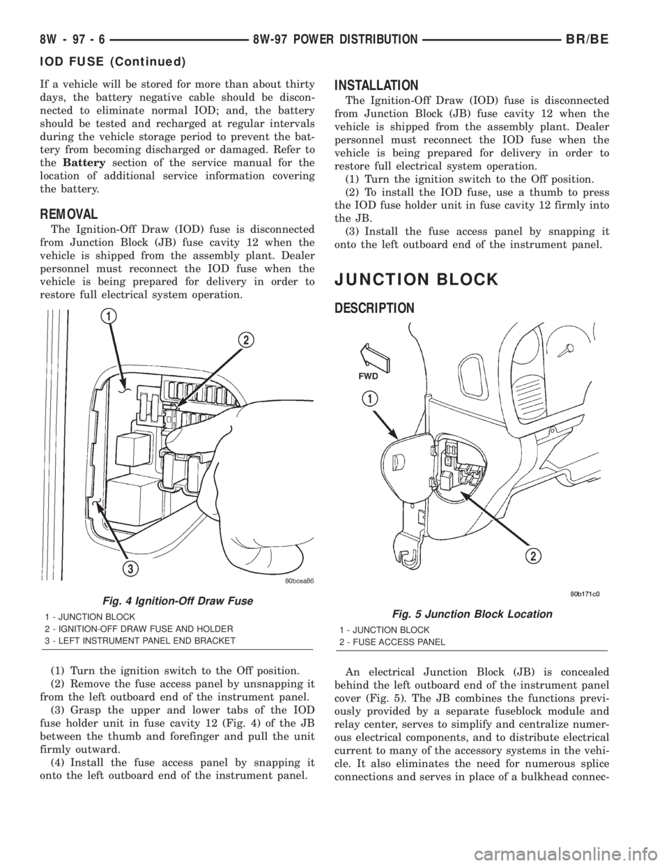
(3) Grasp the upper and lower tabs of the IOD
fuse holder unit in fuse cavity 12 (Fig. 4) of the JB
between the thumb and forefinger and pull the unit
firmly outward.
(4) Install the fuse access panel by snapping it
onto the left outboard end of the instrument panel.
INSTALLATION
The Ignition-Off Draw (IOD) fuse is disconnected
from Junction Block (JB) fuse cavity 12 when the
vehicle is shipped from the assembly plant. Dealer
personnel must reconnect the IOD fuse when the
vehicle is being prepared for delivery in order to
restore full electrical system operation.
(1) Turn the ignition switch to the Off position.
(2) To install the IOD fuse, use a thumb to press
the IOD fuse holder unit in fuse cavity 12 firmly into
the JB.
(3) Install the fuse access panel by snapping it
onto the left outboard end of the instrument panel.
JUNCTION BLOCK
DESCRIPTION
An electrical Junction Block (JB) is concealed
behind the left outboard end of the instrument panel
cover (Fig. 5). The JB combines the functions previ-
ously provided by a separate fuseblock module and
relay center, serves to simplify and centralize numer-
ous electrical components, and to distribute electrical
current to many of the accessory systems in the vehi-
cle. It also eliminates the need for numerous splice
connections and serves in place of a bulkhead connec-
Fig. 4 Ignition-Off Draw Fuse
1 - JUNCTION BLOCK
2 - IGNITION-OFF DRAW FUSE AND HOLDER
3 - LEFT INSTRUMENT PANEL END BRACKETFig. 5 Junction Block Location
1 - JUNCTION BLOCK
2 - FUSE ACCESS PANEL
8W - 97 - 6 8W-97 POWER DISTRIBUTIONBR/BE
IOD FUSE (Continued)
Page 1120 of 2255
(4) If dye is not observed, drive the vehicle at var-
ious speeds for approximately 24km (15 miles), and
repeat previous step.
(5) If the oil leak source is not positively identified
at this time, proceed with the air leak detection test
method as follows:
(6) Disconnect the breather cap to air cleaner hose
at the breather cap end. Cap or plug breather cap
nipple.
(7) Remove the PCV valve from the cylinder head
cover. Cap or plug the PCV valve grommet.
(8) Attach an air hose with pressure gauge and
regulator to the dipstick tube.
CAUTION: Do not subject the engine assembly to
more than 20.6 kpa (3 PSI) of test pressure.
(9) Gradually apply air pressure from 1 psi to 2.5
psi maximum while applying soapy water at the sus-
pected source. Adjust the regulator to the suitable
test pressure that provide the best bubbles which
will pinpoint the leak source. If the oil leak is
detected and identified, repair per service manual
procedures.
(10) If the leakage occurs at the rear oil seal area,
refer to the section, Inspection for Rear Seal Area
Leak.
(11) If no leaks are detected, turn off the air sup-
ply and remove the air hose and all plugs and caps.
Install the PCV valve and breather cap hose. Proceed
to next step.
(12) Clean the oil off the suspect oil leak area
using a suitable solvent. Drive the vehicle at various
speeds approximately 24 km (15 miles). Inspect the
engine for signs of an oil leak by using a black light.
DIAGNOSIS AND TESTINGÐENGINE OIL
PRESSURE
(1) Remove oil pressure sending unit.
(2) Install Oil Pressure Line and Gauge Tool
C-3292. Start engine and record pressure. (Refer to 9
- ENGINE - SPECIFICATIONS).
OIL
STANDARD PROCEDURE - ENGINE OIL
OIL LEVEL INDICATOR (DIPSTICK)
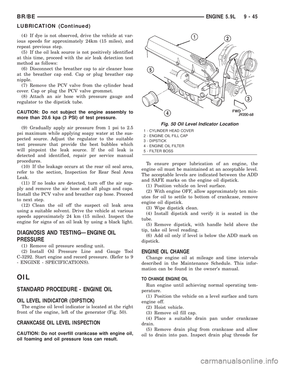
The engine oil level indicator is located at the right
front of the engine, left of the generator (Fig. 50).
CRANKCASE OIL LEVEL INSPECTION
CAUTION: Do not overfill crankcase with engine oil,
oil foaming and oil pressure loss can result.To ensure proper lubrication of an engine, the
engine oil must be maintained at an acceptable level.
The acceptable levels are indicated between the ADD
and SAFE marks on the engine oil dipstick.
(1) Position vehicle on level surface.
(2) With engine OFF, allow approximately ten min-
utes for oil to settle to bottom of crankcase, remove
engine oil dipstick.
(3) Wipe dipstick clean.
(4) Install dipstick and verify it is seated in the
tube.
(5) Remove dipstick, with handle held above the
tip, take oil level reading.
(6) Add oil only if level is below the ADD mark on
dipstick.
ENGINE OIL CHANGE
Change engine oil at mileage and time intervals
described in the Maintenance Schedule. This infor-
mation can be found in the owner's manual.
TO CHANGE ENGINE OIL
Run engine until achieving normal operating tem-
perature.
(1) Position the vehicle on a level surface and turn
engine off.
(2) Hoist vehicle.
(3) Remove oil fill cap.
(4) Place a suitable drain pan under crankcase
drain.
(5) Remove drain plug from crankcase and allow
oil to drain into pan. Inspect drain plug threads for
Fig. 50 Oil Level Indicator Location
1 - CYLINDER HEAD COVER
2 - ENGINE OIL FILL CAP
3 - DIPSTICK
4 - ENGINE OIL FILTER
5 - FILTER BOSS
BR/BEENGINE 5.9L 9 - 45
LUBRICATION (Continued)
Page 1200 of 2255
REMOVALÐCRANKCASE BREATHER VAPOR
CANISTER
NOTE: It is recommended to empty the contents of
the vapor canister at each oil and filter service
interval.
(1) Loosen cap from top of vapor canister.
(2) Remove nut retaining canister to engine front
cover.
(3) Slide clamp upwards on hose, then remove
hose from crankcase breather.
INSTALLATION
INSTALLATIONÐENGINE
(1) Install the engine with the cylinder head cover
and the #5 and 6 rocker arm assemblies removed.
(2) Lower the engine into the compartment and
install the engine mount through bolts and nuts.
(3) Tighten the mount through bolts and nuts to
88 N´m (65 ft. lbs.) torque.
(4) Remove the engine lifting device.
(5) Install the #5 and #6 rocker arms and pedes-
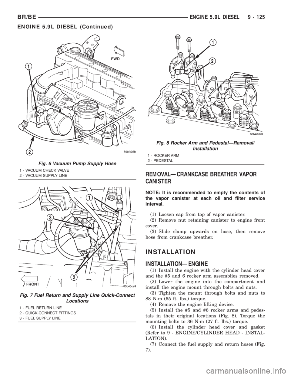
tals in their original locations (Fig. 8). Torque the
mounting bolts to 36 N´m (27 ft. lbs.) torque.
(6) Install the cylinder head cover and gasket
(Refer to 9 - ENGINE/CYLINDER HEAD - INSTAL-
LATION).
(7) Connect the fuel supply and return hoses (Fig.
7).
Fig. 6 Vacuum Pump Supply Hose
1 - VACUUM CHECK VALVE
2 - VACUUM SUPPLY LINE
Fig. 7 Fuel Return and Supply Line Quick-Connect
Locations
1 - FUEL RETURN LINE
2 - QUICK-CONNECT FITTINGS
3 - FUEL SUPPLY LINE
Fig. 8 Rocker Arm and PedestalÐRemoval/
Installation
1 - ROCKER ARM
2 - PEDESTAL
BR/BEENGINE 5.9L DIESEL 9 - 125
ENGINE 5.9L DIESEL (Continued)