warning lights DODGE RAM 2002 Service Repair Manual
[x] Cancel search | Manufacturer: DODGE, Model Year: 2002, Model line: RAM, Model: DODGE RAM 2002Pages: 2255, PDF Size: 62.07 MB
Page 361 of 2255
²Head/Park Lights-On Warning- The CTM
chime tone generator will generate repetitive chime
tones at a fast rate to announce that hard wired
inputs from the driver door ajar switch, headlamp
switch, and ignition switch indicate that the exterior
lamps are turned On with the driver side front door
opened and the ignition switch in the Off position.
The chimes will continue to sound until the exterior
lamps are turned Off, the driver side front door is
closed, or the ignition switch is turned to the On
position, whichever occurs first.
²Key-In-Ignition Warning- The CTM chime
tone generator will generate repetitive chime tones at
a fast rate to announce that hard wired inputs from
the driver door ajar switch, headlamp switch, and
ignition switch indicate that the key is in the ignition
lock cylinder with the driver side front door opened
and the ignition switch in the Off position. The
chimes will continue to sound until the key is
removed from the ignition lock cylinder, the driver
side front door is closed, or the ignition switch is
turned to the On position, whichever occurs first.
²Warning Chime Support- The CTM chime
tone generator will generate repetitive chime tones at
a slow rate to announce that a hard wired chime
request input has been received from the EMIC.
These chime tones provide an audible alert to the
vehicle operator that supplements certain visual indi-
cations displayed by the EMIC. Supplemented indica-
tions include the following:
²The ªAirbagº indicator is illuminated. The
chimes will continue to sound for a duration of about
four seconds each time the indicator is illuminated or
until the ignition switch is turned to the Off position,
whichever occurs first.
²The ªCheck Gagesº indicator is illuminated. The
chimes will continue to sound for a duration of about
two seconds each time the indicator is illuminated or
until the ignition switch is turned to the Off position,
whichever occurs first.
²The ªLow Fuelº indicator is illuminated. The
chimes will continue to sound for a duration of about
two seconds each time the indicator is illuminated or
until the ignition switch is turned to the Off position,
whichever occurs first.
²The ªLow Washº indicator is illuminated. The
chimes will continue to sound for a duration of about
two seconds each time the indicator is illuminated or
until the ignition switch is turned to the Off position,
whichever occurs first.
²The ªTrans Tempº indicator is illuminated (auto-
matic transmission only). The chimes will continue to
sound for a duration of about two seconds each time
the indicator is illuminated or until the ignition
switch is turned to the Off position, whichever occurs
first.²The vehicle is over a programmed speed value
(Middle East Gulf Coast Country (GCC) only). The
CTM chime tone generator will generate repetitive
chime tones at a slow rate to announce that the vehi-
cle speed exceeds a programmed value. The chimes
will continue to sound until the vehicle speed is
below the programmed value.
²The ªWater-In-Fuelº indicator is illuminated
(diesel engine only). The chimes will continue to
sound for a duration of about two seconds each time
the indicator is illuminated or until the ignition
switch is turned to the Off position, whichever occurs
first.
The CTM provides chime service for all available
features in the chime warning system. The CTM
relies upon hard wired inputs from the driver door
ajar switch, the EMIC, the headlamp switch, and the
key-in ignition switch (ignition switch) to provide
chime service for all of the chime warning system
features. Upon receiving the proper inputs, the CTM
activates the integral chime tone generator to pro-
vide the audible chime tone to the vehicle operator.
The chime tone generator in the CTM is capable of
producing repeated chime tones at two different
rates, slow or fast. The slow chime rate is about fifty
chime tones per minute, while the fast chime rate is
about 180 chime tones per minute. The internal pro-
gramming of the CTM and the EMIC determines the
priority of each chime tone request input that is
received, as well as the rate and duration of each
chime tone that is to be generated.
The hard wired chime warning system inputs to
the CTM and the EMIC, as well as other hard wired
circuits for this system may be diagnosed and tested
using conventional diagnostic tools and procedures.
See the owner's manual in the vehicle glove box for
more information on the features provided by the
chime warning system.
DIAGNOSIS AND TESTING - CHIME WARNING
SYSTEM
Refer to the appropriate wiring information. The
wiring information includes wiring diagrams, proper
wire and connector repair procedures, further details
on wire harness routing and retention, as well as
pin-out and location views for the various wire har-
ness connectors, splices and grounds. The hard wired
chime warning system inputs to the Central Timer
Module (CTM) and the Electro-Mechanical Instru-
ment Cluster (EMIC), as well as other hard wired
circuits for this system may be diagnosed and tested
using conventional diagnostic tools and procedures.
8B - 2 CHIME/BUZZERBR/BE
CHIME WARNING SYSTEM (Continued)
Page 522 of 2255
CLEARANCE LAMP
REMOVAL
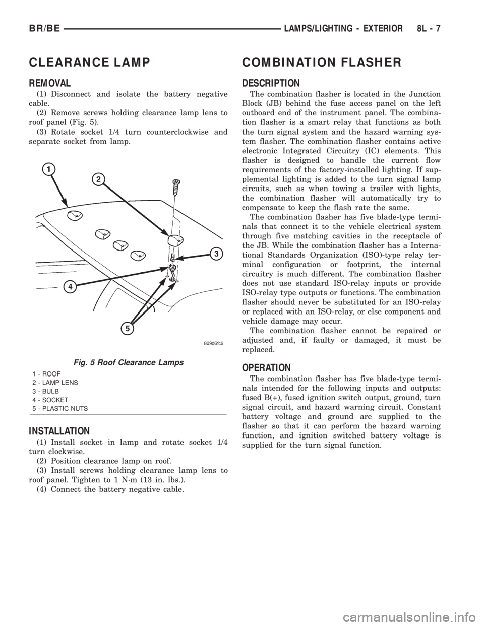
(1) Disconnect and isolate the battery negative
cable.
(2) Remove screws holding clearance lamp lens to
roof panel (Fig. 5).
(3) Rotate socket 1/4 turn counterclockwise and
separate socket from lamp.
INSTALLATION
(1) Install socket in lamp and rotate socket 1/4
turn clockwise.
(2) Position clearance lamp on roof.
(3) Install screws holding clearance lamp lens to
roof panel. Tighten to 1 N´m (13 in. lbs.).
(4) Connect the battery negative cable.
COMBINATION FLASHER
DESCRIPTION
The combination flasher is located in the Junction
Block (JB) behind the fuse access panel on the left
outboard end of the instrument panel. The combina-
tion flasher is a smart relay that functions as both
the turn signal system and the hazard warning sys-
tem flasher. The combination flasher contains active
electronic Integrated Circuitry (IC) elements. This
flasher is designed to handle the current flow
requirements of the factory-installed lighting. If sup-
plemental lighting is added to the turn signal lamp
circuits, such as when towing a trailer with lights,
the combination flasher will automatically try to
compensate to keep the flash rate the same.
The combination flasher has five blade-type termi-
nals that connect it to the vehicle electrical system
through five matching cavities in the receptacle of
the JB. While the combination flasher has a Interna-
tional Standards Organization (ISO)-type relay ter-
minal configuration or footprint, the internal
circuitry is much different. The combination flasher
does not use standard ISO-relay inputs or provide
ISO-relay type outputs or functions. The combination
flasher should never be substituted for an ISO-relay
or replaced with an ISO-relay, or else component and
vehicle damage may occur.
The combination flasher cannot be repaired or
adjusted and, if faulty or damaged, it must be
replaced.
OPERATION
The combination flasher has five blade-type termi-
nals intended for the following inputs and outputs:
fused B(+), fused ignition switch output, ground, turn
signal circuit, and hazard warning circuit. Constant
battery voltage and ground are supplied to the
flasher so that it can perform the hazard warning
function, and ignition switched battery voltage is
supplied for the turn signal function.
Fig. 5 Roof Clearance Lamps
1 - ROOF
2 - LAMP LENS
3 - BULB
4 - SOCKET
5 - PLASTIC NUTS
BR/BELAMPS/LIGHTING - EXTERIOR 8L - 7
Page 524 of 2255
INSTALLATION
WARNING: ON VEHICLES EQUIPPED WITH AIR-
BAGS, DISABLE THE AIRBAG SYSTEM BEFORE
ATTEMPTING ANY STEERING WHEEL, STEERING
COLUMN, OR INSTRUMENT PANEL COMPONENT
DIAGNOSIS OR SERVICE. DISCONNECT AND ISO-
LATE THE BATTERY NEGATIVE (GROUND) CABLE,
THEN WAIT TWO MINUTES FOR THE AIRBAG SYS-
TEM CAPACITOR TO DISCHARGE BEFORE PER-
FORMING FURTHER DIAGNOSIS OR SERVICE. THIS
IS THE ONLY SURE WAY TO DISABLE THE AIRBAG
SYSTEM. FAILURE TO TAKE THE PROPER PRE-
CAUTIONS COULD RESULT IN ACCIDENTAL AIR-
BAG DEPLOYMENT AND POSSIBLE PERSONAL
INJURY.
(1) Position the combination flasher in the proper
receptacle of the Junction Block (JB).
(2) Align the terminals of the combination flasher
with the terminal cavities in the JB receptacle for
the flasher.
(3) Push in firmly and evenly on the combination
flasher until the terminals are fully seated in the ter-
minal cavities of the JB receptacle for the flasher.
(4) Reinstall the fuse access panel by snapping it
onto the left outboard end of the instrument panel.
(5) Reconnect the battery negative cable.
DAYTIME RUNNING LAMP
MODULE
DESCRIPTION
The Daytime Running Lights (Headlamps) System
is installed on vehicles manufactured for sale in Can-
ada only. A separate module, mounted on the cowl,
controls the DRL.
OPERATION
The headlamps are illuminated when the ignition
switch is turned to the ON position. The DRL module
receives a vehicle-moving signal from the vehicle
speed sensor. This provides a constanthead-
lamps-oncondition as long as the vehicle is moving.
The lamps are illuminated at less than 50 percent of
normal intensity.
REMOVAL
(1) Disconnect and isolate the battery negative
cable.
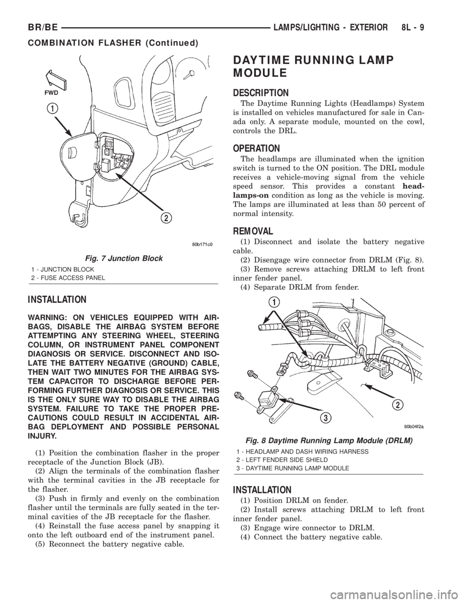
(2) Disengage wire connector from DRLM (Fig. 8).
(3) Remove screws attaching DRLM to left front
inner fender panel.
(4) Separate DRLM from fender.
INSTALLATION
(1) Position DRLM on fender.
(2) Install screws attaching DRLM to left front
inner fender panel.
(3) Engage wire connector to DRLM.
(4) Connect the battery negative cable.
Fig. 7 Junction Block
1 - JUNCTION BLOCK
2 - FUSE ACCESS PANEL
Fig. 8 Daytime Running Lamp Module (DRLM)
1 - HEADLAMP AND DASH WIRING HARNESS
2 - LEFT FENDER SIDE SHIELD
3 - DAYTIME RUNNING LAMP MODULE
BR/BELAMPS/LIGHTING - EXTERIOR 8L - 9
COMBINATION FLASHER (Continued)
Page 598 of 2255
CAUTION: All damaged, faulty, or non-deployed air-
bags which are replaced on vehicles are to handled
and disposed of properly. If an airbag unit is faulty
or damaged and non-deployed, refer to the Hazard-
ous Substance Control System for proper disposal.
Dispose of all non-deployed and deployed airbags
in a manner consistent with state, provincial, local
and federal regulations.
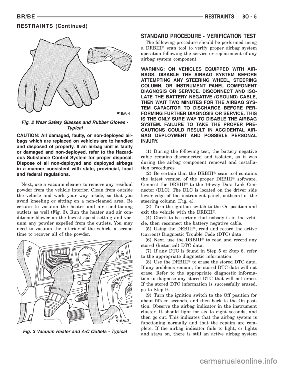
Next, use a vacuum cleaner to remove any residual
powder from the vehicle interior. Clean from outside
the vehicle and work your way inside, so that you
avoid kneeling or sitting on a non-cleaned area. Be
certain to vacuum the heater and air conditioning
outlets as well (Fig. 3). Run the heater and air con-
ditioner blower on the lowest speed setting and vac-
uum any powder expelled from the outlets. You may
need to vacuum the interior of the vehicle a second
time to recover all of the powder.
STANDARD PROCEDURE - VERIFICATION TEST
The following procedure should be performed using
a DRBIIItscan tool to verify proper airbag system
operation following the service or replacement of any
airbag system component.
WARNING: ON VEHICLES EQUIPPED WITH AIR-
BAGS, DISABLE THE AIRBAG SYSTEM BEFORE
ATTEMPTING ANY STEERING WHEEL, STEERING
COLUMN, OR INSTRUMENT PANEL COMPONENT
DIAGNOSIS OR SERVICE. DISCONNECT AND ISO-
LATE THE BATTERY NEGATIVE (GROUND) CABLE,
THEN WAIT TWO MINUTES FOR THE AIRBAG SYS-
TEM CAPACITOR TO DISCHARGE BEFORE PER-
FORMING FURTHER DIAGNOSIS OR SERVICE. THIS
IS THE ONLY SURE WAY TO DISABLE THE AIRBAG
SYSTEM. FAILURE TO TAKE THE PROPER PRE-
CAUTIONS COULD RESULT IN ACCIDENTAL AIR-
BAG DEPLOYMENT AND POSSIBLE PERSONAL
INJURY.
(1) During the following test, the battery negative
cable remains disconnected and isolated, as it was
during the airbag component removal and installa-
tion procedures.
(2) Be certain that the DRBIIItscan tool contains
the latest version of the proper DRBIIItsoftware.
Connect the DRBIIItto the 16-way Data Link Con-
nector (DLC). The DLC is located on the driver side
lower edge of the instrument panel, outboard of the
steering column (Fig. 4).
(3) Turn the ignition switch to the On position and
exit the vehicle with the DRBIIIt.
(4) Check to be certain that nobody is in the vehi-
cle, then reconnect the battery negative cable.
(5) Using the DRBIIIt, read and record the active
(current) Diagnostic Trouble Code (DTC) data.
(6) Next, use the DRBIIItto read and record any
stored (historical) DTC data.
(7) If any DTC is found in Step 5 or Step 6, refer
to the appropriate diagnostic information.
(8) Use the DRBIIItto erase the stored DTC data.
If any problems remain, the stored DTC data will not
erase. Refer to the appropriate diagnostic informa-
tion to diagnose any stored DTC that will not erase.
If the stored DTC information is successfully erased,
go to Step 9.
(9) Turn the ignition switch to the Off position for
about fifteen seconds, and then back to the On posi-
tion. Observe the airbag indicator in the instrument
cluster. It should light for six to eight seconds, and
then go out. This indicates that the airbag system is
functioning normally and that the repairs are com-
plete. If the airbag indicator fails to light, or lights
and stays on, there is still an active airbag system
Fig. 2 Wear Safety Glasses and Rubber Gloves -
Typical
Fig. 3 Vacuum Heater and A/C Outlets - Typical
BR/BERESTRAINTS 8O - 5
RESTRAINTS (Continued)
Page 1969 of 2255
DIAGNOSIS AND TESTING
DIAGNOSIS AND TESTING - WATER LEAKS
Water leaks can be caused by poor sealing,
improper body component alignment, body seam
porosity, missing plugs, or blocked drain holes. Cen-
trifugal and gravitational force can cause water to
drip from a location away from the actual leak point,
making leak detection difficult. All body sealing
points should be water tight in normal wet-driving
conditions. Water flowing downward from the front of
the vehicle should not enter the passenger or luggage
compartment. Moving sealing surfaces will not
always seal water tight under all conditions. At
times, side glass or door seals will allow water to
enter the passenger compartment during high pres-
sure washing or hard driving rain (severe) condi-
tions. Overcompensating on door or glass
adjustments to stop a water leak that occurs under
severe conditions can cause premature seal wear and
excessive closing or latching effort. After completing
a repair, water test vehicle to verify leak has stopped
before returning vehicle to use.
VISUAL INSPECTION BEFORE WATER LEAK TESTS
Verify that floor and body plugs are in place, body
drains are clear, and body components are properly
aligned and sealed. If component alignment or seal-
ing is necessary, refer to the appropriate section of
this group for proper procedures.
WATER LEAK TESTS
WARNING: DO NOT USE ELECTRIC SHOP LIGHTS
OR TOOLS IN WATER TEST AREA. PERSONAL
INJURY CAN RESULT.
When the conditions causing a water leak have
been determined, simulate the conditions as closely
as possible.
²If a leak occurs with the vehicle parked in a
steady light rain, flood the leak area with an open-
ended garden hose.²If a leak occurs while driving at highway speeds
in a steady rain, test the leak area with a reasonable
velocity stream or fan spray of water. Direct the
spray in a direction comparable to actual conditions.
²If a leak occurs when the vehicle is parked on an
incline, hoist the end or side of the vehicle to simu-
late this condition. This method can be used when
the leak occurs when the vehicle accelerates, stops or
turns. If the leak occurs on acceleration, hoist the
front of the vehicle. If the leak occurs when braking,
hoist the back of the vehicle. If the leak occurs on left
turns, hoist the left side of the vehicle. If the leak
occurs on right turns, hoist the right side of the vehi-
cle. For hoisting recommendations refer to Group 0,
Lubrication and Maintenance, General Information
section.
WATER LEAK DETECTION
To detect a water leak point-of-entry, do a water
test and watch for water tracks or droplets forming
on the inside of the vehicle. If necessary, remove inte-
rior trim covers or panels to gain visual access to the
leak area. If the hose cannot be positioned without
being held, have someone help do the water test.
Some water leaks must be tested for a considerable
length of time to become apparent. When a leak
appears, find the highest point of the water track or
drop. The highest point usually will show the point of
entry. After leak point has been found, repair the
leak and water test to verify that the leak has
stopped.
Locating the entry point of water that is leaking
into a cavity between panels can be difficult. The
trapped water may splash or run from the cavity,
often at a distance from the entry point. Most water
leaks of this type become apparent after accelerating,
stopping, turning, or when on an incline.
MIRROR INSPECTION METHOD
When a leak point area is visually obstructed, use
a suitable mirror to gain visual access. A mirror can
also be used to deflect light to a limited-access area
to assist in locating a leak point.
23 - 2 BODYBR/BE
BODY (Continued)