wire diagram of pcm DODGE RAM 2002 Service Repair Manual
[x] Cancel search | Manufacturer: DODGE, Model Year: 2002, Model line: RAM, Model: DODGE RAM 2002Pages: 2255, PDF Size: 62.07 MB
Page 349 of 2255
RADIO NOISE SUPPRESSION
COMPONENTS
DESCRIPTION
Radio Frequency Interference (RFI) and Electro-
Magnetic Interference (EMI) noise suppression is
accomplished primarily through circuitry internal to
the radio receivers. These internal suppression
devices are only serviced as part of the radio receiver.
External suppression devices that are used on this
vehicle to control RFI or EMI noise include the fol-
lowing:
²Radio antenna base ground
²Radio receiver chassis ground wire or strap
²Engine-to-body ground straps
²Cab-to-bed ground strap
²Heater core ground strap
²Resistor-type spark plugs
²Radio suppression-type secondary ignition wir-
ing.
For more information on the spark plugs and sec-
ondary ignition components, refer to Electrical, Igni-
tion Control.
DIAGNOSIS AND TESTING - RADIO NOISE
SUPPRESSION COMPONENTS
WARNING: ON VEHICLES EQUIPPED WITH AIR-
BAGS, REFER TO ELECTRICAL, RESTRAINTS
BEFORE ATTEMPTING ANY STEERING WHEEL,
STEERING COLUMN, OR INSTRUMENT PANEL
COMPONENT DIAGNOSIS OR SERVICE. FAILURE
TO TAKE THE PROPER PRECAUTIONS COULD
RESULT IN ACCIDENTAL AIRBAG DEPLOYMENT
AND POSSIBLE PERSONAL INJURY.
For complete circuit diagrams, refer to the appro-
priate wiring information. The wiring information
includes wiring diagrams, proper wire and connector
repair procedures, details of wire harness routing
and retention, connector pin-out information and
location views for the various wire harness connec-
tors, splices and grounds. Inspect the ground paths
and connections at the following locations:
²Blower motor
²Cab-to-bed ground strap
²Electric fuel pump
²Engine-to-body ground straps
²Generator
²Ignition module
²Heater core ground strap
²Radio antenna base ground
²Radio receiver chassis ground wire or strap
²Wiper motor.If the source of RFI or EMI noise is identified as a
component on the vehicle (i.e., generator, blower
motor, etc.), the ground path for that component
should be checked. If excessive resistance is found in
any ground circuit, clean, tighten, or repair the
ground circuits or connections to ground as required
before considering any component replacement.
For service and inspection of secondary ignition
components, refer to Electrical, Ignition Control.
Inspect the following secondary ignition system com-
ponents:
²Distributor cap and rotor
²Ignition coil
²Spark plugs
²Spark plug wire routing and condition.
Reroute the spark plug wires or replace the faulty
components as required.
If the source of the RFI or EMI noise is identified
as two-way mobile radio or telephone equipment,
check the equipment installation for the following:
²Power connections should be made directly to
the battery, and fused as closely to the battery as
possible.
²The antenna should be mounted on the roof or
toward the rear of the vehicle. Remember that mag-
netic antenna mounts on the roof panel can adversely
affect the operation of an overhead console compass,
if the vehicle is so equipped.
²The antenna cable should be fully shielded coax-
ial cable, should be as short as is practical, and
should be routed away from the factory-installed
vehicle wire harnesses whenever possible.
²The antenna and cable must be carefully
matched to ensure a low Standing Wave Ratio
(SWR).
Fleet vehicles are available with an extra-cost RFI-
suppressed Powertrain Control Module (PCM). This
unit reduces interference generated by the PCM on
some radio frequencies used in two-way radio com-
munications. However, this unit will not resolve com-
plaints of RFI in the commercial AM or FM radio
frequency ranges.
ENGINE-TO-BODY GROUND
STRAP
REMOVAL
(1) Remove the screw that secures the engine-to-
body ground strap eyelet to the dash panel (Fig. 10).
(2) Remove the screw that secures the engine-to-
body ground strap eyelet to the back of the engine
cylinder head (Fig. 11) or (Fig. 12).
8A - 12 AUDIOBR/BE
Page 369 of 2255
HARD WIRED OUTPUTS
The hard wired outputs of the CTM include the fol-
lowing:
²CCD bus± - high-line/premium version only
²CCD bus+ - high-line/premium version only
²Courtesy lamp switch output - high-line/pre-
mium version only
²Door lock driver - high-line/premium version
only
²Door unlock driver - high-line/premium version
only
²Headlamp relay control - high-line/premium ver-
sion only
²Heated seat relay control - premium version
only
²Horn relay control - high-line/premium version
only
²VTSS indicator driver - high-line/premium ver-
sion only
²Wiper motor relay control
MESSAGING
The high-line/premium CTM uses the following
messages received from other electronic modules over
the CCD data bus:
²Airbag Deploy (ACM)
²Charging System Failure (PCM)
²Engine RPM (PCM)
²System Voltage (PCM)
²Vehicle Speed (PCM)
²Voltage Fault (PCM)
The high-line/premium CTM provides the following
messages to other electronic modules over the CCD
data bus:
²Engine Enable (PCM)
²Radio Seek Up (Radio)
²Radio Seek Down (Radio)
²Radio Volume Up (Radio)
²Radio Volume Down (Radio)
²Preset Scan (Radio)
DIAGNOSIS AND TESTING - CENTRAL TIMER
MODULE
The hard wired inputs to and outputs from the
Central Timer Module (CTM) may be diagnosed and
tested using conventional diagnostic tools and meth-
ods. Refer to the appropriate wiring information. The
wiring information includes wiring diagrams, proper
wire and connector repair procedures, further details
on wire harness routing and retention, as well as
pin-out and location views for the various wire har-
ness connectors, splices and grounds.
However, conventional diagnostic methods may not
prove conclusive in the diagnosis of the high-line/pre-
mium CTM. In order to obtain conclusive testing of
the high-line/premium CTM, the Chrysler CollisionDetection (CCD) data bus network and all of the elec-
tronic modules that provide inputs to or receive out-
puts from the CTM must also be checked. The most
reliable, efficient, and accurate means to diagnose
the high-line/premium CTM, the CCD data bus net-
work, and the electronic modules that provide inputs
to or receive outputs from the high-line/premium
CTM requires the use of a DRBIIItscan tool and the
appropriate diagnostic information. The DRBIIIt
scan tool can provide confirmation that the CCD data
bus network is functional, that all of the electronic
modules are sending and receiving the proper mes-
sages over the CCD data bus, and that the CTM is
receiving the proper hard wired inputs and respond-
ing with the proper hard wired outputs needed to
perform its many functions.
WARNING: ON VEHICLES EQUIPPED WITH AIR-
BAGS, DISABLE THE AIRBAG SYSTEM BEFORE
ATTEMPTING ANY STEERING WHEEL, STEERING
COLUMN, OR INSTRUMENT PANEL COMPONENT
DIAGNOSIS OR SERVICE. DISCONNECT AND ISO-
LATE THE BATTERY NEGATIVE (GROUND) CABLE,
THEN WAIT TWO MINUTES FOR THE AIRBAG SYS-
TEM CAPACITOR TO DISCHARGE BEFORE PER-
FORMING FURTHER DIAGNOSIS OR SERVICE. THIS
IS THE ONLY SURE WAY TO DISABLE THE AIRBAG
SYSTEM. FAILURE TO TAKE THE PROPER PRE-
CAUTIONS COULD RESULT IN ACCIDENTAL AIR-
BAG DEPLOYMENT AND POSSIBLE PERSONAL
INJURY.
NOTE: The following tests may not prove conclu-
sive in the diagnosis of the high-line or premium
versions of the Central Timer Module (CTM). The
most reliable, efficient, and accurate means to diag-
nose the high-line or premium CTM requires the
use of a DRBIIITscan tool and the appropriate diag-
nostic information.
(1) Check the fused B(+) fuse (Fuse 13 - 10
ampere) in the Junction Block (JB). If OK, go to Step
2. If not OK, repair the shorted circuit or component
as required and replace the faulty fuse.
(2) Check for battery voltage at the fused B(+) fuse
(Fuse 13 - 10 ampere) in the JB. If OK, go to Step 3.
If not OK, repair the open fused B(+) circuit between
the JB and the Power Distribution Center (PDC) as
required.
(3) For a base version CTM, check the fused igni-
tion switch output (st-run) fuse (Fuse 11 - 10 ampere)
in the JB. For a high-line/premium version CTM,
check the fused ignition switch output (run-acc) fuse
(Fuse6-25ampere) in the JB. If OK, go to Step 4. If
not OK, repair the shorted circuit or component as
required and replace the faulty fuse.
8E - 4 ELECTRONIC CONTROL MODULESBR/BE
CENTRAL TIMER MODULE (Continued)
Page 446 of 2255
ical dimensions are smaller than those of the conven-
tional ISO relay.
The heated seat relay cannot be repaired or
adjusted and, if faulty or damaged, it must be
replaced.
OPERATION
The ISO relay consists of an electromagnetic coil, a
resistor or diode, and three (two fixed and one mov-
able) electrical contacts. The movable (common feed)
relay contact is held against one of the fixed contacts
(normally closed) by spring pressure. When the elec-
tromagnetic coil is energized, it draws the movable
contact away from the normally closed fixed contact,
and holds it against the other (normally open) fixed
contact. When the electromagnetic coil is de-ener-
gized, spring pressure returns the movable contact to
the normally closed position. The resistor or diode is
connected in parallel with the electromagnetic coil in
the relay, and helps to dissipate voltage spikes that
are produced when the coil is de-energized.
The heated seat relay is controlled by the premium
version of the Central Timer Module (CTM), which
controls the ground feed to the coil ground terminal
of the relay to energize and de-energize the electro-
magnetic coil of the relay. The CTM monitors engine
operation through messages it receives from the Pow-
ertrain Control Module (PCM) over the Chrysler Col-
lision Detection (CCD) data bus network. The CTM is
programmed to energize the relay only when the
engine is running, and to de-energize the relay when
the engine is not running. Refer toCentral Timer
Modulein the index of this service manual for the
location of more information on the premium CTM.
DIAGNOSIS AND TESTING - HEATED SEAT
RELAY
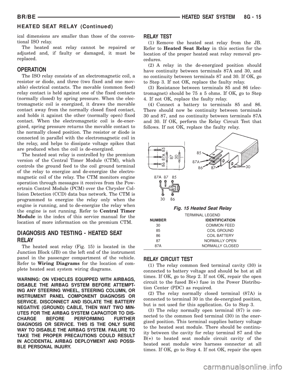
The heated seat relay (Fig. 15) is located in the
Junction Block (JB) on the left end of the instrument
panel in the passenger compartment of the vehicle.
Refer toWiring Diagramsfor the location of com-
plete heated seat system wiring diagrams.
WARNING: ON VEHICLES EQUIPPED WITH AIRBAGS,
DISABLE THE AIRBAG SYSTEM BEFORE ATTEMPT-
ING ANY STEERING WHEEL, STEERING COLUMN, OR
INSTRUMENT PANEL COMPONENT DIAGNOSIS OR
SERVICE. DISCONNECT AND ISOLATE THE BATTERY
NEGATIVE (GROUND) CABLE, THEN WAIT TWO MIN-
UTES FOR THE AIRBAG SYSTEM CAPACITOR TO DIS-
CHARGE BEFORE PERFORMING FURTHER
DIAGNOSIS OR SERVICE. THIS IS THE ONLY SURE
WAY TO DISABLE THE AIRBAG SYSTEM. FAILURE TO
TAKE THE PROPER PRECAUTIONS COULD RESULT
IN ACCIDENTAL AIRBAG DEPLOYMENT AND POSSI-
BLE PERSONAL INJURY.
RELAY TEST
(1) Remove the heated seat relay from the JB.
Refer toHeated Seat Relayin this section for the
location of the proper heated seat relay removal pro-
cedures.
(2) A relay in the de-energized position should
have continuity between terminals 87A and 30, and
no continuity between terminals 87 and 30. If OK, go
to Step 3. If not OK, replace the faulty relay.
(3) Resistance between terminals 85 and 86 (elec-
tromagnet) should be 75 5 ohms. If OK, go to Step
4. If not OK, replace the faulty relay.
(4) Connect a battery to terminals 85 and 86.
There should now be continuity between terminals
30 and 87, and no continuity between terminals 87A
and 30. If OK, perform the Relay Circuit Test that
follows. If not OK, replace the faulty relay.
RELAY CIRCUIT TEST
(1) The relay common feed terminal cavity (30) is
connected to battery voltage and should be hot at all
times. If OK, go to Step 2. If not OK, repair the open
circuit to the fused B(+) fuse in the Power Distribu-
tion Center (PDC) as required.
(2) The relay normally closed terminal (87A) is
connected to terminal 30 in the de-energized position,
but is not used for this application. Go to Step 3.
(3) The relay normally open terminal (87) is con-
nected to the common feed terminal (30) in the ener-
gized position. This terminal supplies battery voltage
to the heated seat module. There should be continu-
ity between the cavity for relay terminal 87 and the
B(+) to heated seat module circuit cavity of the
heated seat module wire harness connector at all
times. If OK, go to Step 4. If not OK, repair the open
Fig. 15 Heated Seat Relay
TERMINAL LEGEND
NUMBER IDENTIFICATION
30 COMMON FEED
85 COIL GROUND
86 COIL BATTERY
87 NORMALLY OPEN
87A NORMALLY CLOSED
BR/BEHEATED SEAT SYSTEM 8G - 15
HEATED SEAT RELAY (Continued)
Page 501 of 2255
high beam indicator. If no headlamp system problems
are found, the following procedure will help locate a
short or open in the high beam indicator circuit.
Refer to the appropriate wiring information. The wir-
ing information includes wiring diagrams, proper
wire and connector repair procedures, details of wire
harness routing and retention, connector pin-out
information and location views for the various wire
harness connectors, splices and grounds.
WARNING: ON VEHICLES EQUIPPED WITH AIR-
BAGS, DISABLE THE AIRBAG SYSTEM BEFORE
ATTEMPTING ANY STEERING WHEEL, STEERING
COLUMN, OR INSTRUMENT PANEL COMPONENT
DIAGNOSIS OR SERVICE. DISCONNECT AND ISO-
LATE THE BATTERY NEGATIVE (GROUND) CABLE,
THEN WAIT TWO MINUTES FOR THE AIRBAG SYS-
TEM CAPACITOR TO DISCHARGE BEFORE PER-
FORMING FURTHER DIAGNOSIS OR SERVICE. THIS
IS THE ONLY SURE WAY TO DISABLE THE AIRBAG
SYSTEM. FAILURE TO TAKE THE PROPER PRE-
CAUTIONS COULD RESULT IN ACCIDENTAL AIR-
BAG DEPLOYMENT AND POSSIBLE PERSONAL
INJURY.
INDICATOR DOES NOT ILLUMINATE WITH HIGH BEAMS
SELECTED
(1) Check the fused B(+) fuse (Fuse 14 - 10
ampere) in the Junction Block (JB). If OK, go to Step
2. If not OK, repair the shorted circuit or component
as required and replace the faulty fuse.
(2) Check for battery voltage at the fused B(+) fuse
(Fuse 14 - 10 ampere) in the JB. If OK, go to Step 3.
If not OK, repair the open fused B(+) circuit between
the JB and the Power Distribution Center (PDC) as
required.
(3) Be certain that the headlamp high beams are
selected with the headlamp beam select switch by
turning the headlamp switch to the On position, pull-
ing the multi-function switch stalk toward the steer-
ing wheel, then inspecting the headlamps at the
front of the vehicle. Once the headlamp high beams
are selected, turn the headlamp switch to the Off
position. Disconnect and isolate the battery negative
cable. Remove the instrument cluster from the
instrument panel. Reconnect the battery negative
cable. Check for battery voltage at the fused B(+) cir-
cuit cavity of the instrument panel wire harness con-
nector (Connector C1) for the instrument cluster. If
OK, go to Step 4. If not OK, repair the open fused
B(+) circuit between the instrument cluster and the
JB as required.
(4) Disconnect and isolate the battery negative
cable. Check for continuity between the high beam
indicator driver circuit cavity of the instrument panel
wire harness connector (Connector C2) for the instru-ment cluster and a good ground. There should be
continuity. If OK, replace the faulty headlamp high
beam indicator bulb and bulb holder unit. If not OK,
repair the open high beam indicator driver circuit
between the instrument cluster and the headlamp
beam select (multi-function) switch as required.
INDICATOR STAYS ILLUMINATED WITH HIGH BEAMS NOT
SELECTED
(1) Be certain that the headlamp low beams are
selected with the headlamp beam select switch by
turning the headlamp switch to the On position, pull-
ing the multi-function switch stalk toward the steer-
ing wheel, then inspecting the headlamps at the
front of the vehicle. Once the headlamp low beams
are selected, turn the headlamp switch to the Off
position. Disconnect and isolate the battery negative
cable. Remove the instrument cluster from the
instrument panel. Check for continuity between the
high beam indicator driver circuit cavity of the
instrument panel wire harness connector (Connector
C2) for the instrument cluster and a good ground.
There should be no continuity. If OK, replace the
faulty instrument cluster. If not OK, repair the
shorted high beam indicator driver circuit between
the instrument cluster and the headlamp beam select
(multi-function) switch as required.
LOW FUEL INDICATOR
DESCRIPTION
A low fuel indicator is standard equipment on all
instrument clusters. The low fuel indicator is located
near the lower edge of the instrument cluster overlay,
to the right of center. The low fuel indicator consists
of a stenciled cutout of the International Control and
Display Symbol icon for ªFuelº in the opaque layer of
the instrument cluster overlay. The dark outer layer
of the overlay prevents the indicator from being
clearly visible when it is not illuminated. An amber
lens behind the cutout in the opaque layer of the
overlay causes the icon to appear in amber through
the translucent outer layer of the overlay when the
indicator is illuminated from behind by a Light Emit-
ting Diode (LED) soldered onto the instrument clus-
ter electronic circuit board. The low fuel indicator is
serviced as a unit with the instrument cluster.
OPERATION
The low fuel indicator gives an indication to the
vehicle operator when the level of fuel in the fuel
tank becomes low. This indicator is controlled by a
transistor on the instrument cluster circuit board
based upon cluster programming and electronic mes-
sages received by the cluster from the Powertrain
Control Module (PCM) over the Chrysler Collision
8J - 22 INSTRUMENT CLUSTERBR/BE
HIGH BEAM INDICATOR (Continued)
Page 571 of 2255
OPERATION - REMOTE KEYLESS ENTRY
SYSTEM
On vehicles with the Remote Keyless Entry (RKE)
system, the power locks can be operated remotely
using the RKE transmitter. If the vehicle is so
equipped, the RKE transmitter also arms and dis-
arms the factory-installed Vehicle Theft Security Sys-
tem (VTSS). Three small, recessed buttons on the
outside of the transmitter case labelled Lock, Unlock,
and Panic allow the user to choose the function that
is desired. The RKE transmitter then sends the
appropriate Radio Frequency (RF) signal. An RF
receiver that is integral to the high-line or premium
version of the Central Timer Module (CTM) receives
the transmitted signal, then uses its internal elec-
tronic programming to determine whether the
received signal is valid and what function has been
requested. If the signal is valid, the CTM provides
the programmed features.
Besides operating the power lock system and arm-
ing or disarming the VTSS, the RKE system also
controls the following features:
²Horn Chirp- If this feature is enabled, the
CTM provides a horn chirp by internally pulling the
control coil of the horn relay to ground through a
hard wired circuit output.
²Illuminated Entry- The CTM provides illumi-
nated entry by internally controlling the current flow
to the courtesy lamps in the vehicle through a hard
wired output circuit.
²Panic Mode- The CTM provides the horn pulse
and headlight flash by internally pulling the control
coils of the horn relay and headlamp relay to ground
through hard wired circuit outputs. The CTM con-
trols the current flow to the courtesy lamps in the
vehicle through a hard wired output circuit. The
CTM also monitors the vehicle speed through elec-
tronic messages it receives from the Powertrain Con-
trol Module (PCM) over the Chrysler Collision
Detection (CCD) data bus network.
The RKE system operates on battery current
received through a fused B(+) circuit from a fuse in
the Junction Block (JB) so that the system remains
functional, regardless of the ignition switch position.
The RKE system can retain the vehicle access codes
of up to four RKE transmitters. The transmitter
codes are retained in RKE system memory, even if
the battery is disconnected. If a transmitter is faulty
or is lost, new transmitter vehicle access codes can be
programmed into the system using a DRBIIItscan
tool. Refer to the appropriate diagnostic information.
Many of the electronic features in the vehicle con-
trolled or supported by the high-line or premium ver-
sions of the CTM are programmable using the
DRBIIItscan tool. In addition, the high-line/pre-
mium CTM software is Flash compatible, whichmeans it can be reprogrammed using Flash repro-
gramming procedures. However, if any of the CTM
hardware components are damaged or faulty, the
entire CTM unit must be replaced. The hard wired
inputs or outputs of the CTM can be diagnosed using
conventional diagnostic tools and methods; however,
for diagnosis of the high-line or premium versions of
the CTM or the CCD data bus, the use of a DRBIIIt
scan tool is required. Refer to the appropriate diag-
nostic information.
DIAGNOSIS AND TESTING
DIAGNOSIS AND TESTING - POWER LOCKS
The following tests provide a preliminary diagnosis
for the power lock system usedonlyon vehicles
equipped with a base version of the Central Timer
Module (CTM). These testsdo notapply to the diag-
nosis of the power lock system used on vehicles
equipped with the optional Remote Keyless Entry
(RKE) system, which includes a high-line or premium
CTM. (Refer to 8 - ELECTRICAL/POWER LOCKS -
DIAGNOSIS AND TESTING - POWER LOCK &
REMOTE KEYLESS ENTRY SYSTEM). Refer to the
appropriate wiring information. The wiring informa-
tion includes wiring diagrams, proper wire and con-
nector repair procedures, details of wire harness
routing and retention, connector pin-out information
and location views for the various wire harness con-
nectors, splices and grounds.
PRELIMINARY TESTS
To begin this test, note the system operation while
you actuate both the Lock and Unlock functions with
the power lock switches. Then, proceed as follows:
²If the entire power lock system fails to function
with both of the power lock switches, check the fused
B(+) fuse in the Junction Block (JB). If the fuse is
OK, check the ground circuit between the driver side
power lock switch and ground (G301). If the ground
circuit is OK, proceed to the diagnosis of the power
lock motors. (Refer to 8 - ELECTRICAL/POWER
LOCKS/POWER LOCK MOTOR - DIAGNOSIS AND
TESTING).
²If the entire power lock system fails to function
with only one of the power lock switches, proceed to
diagnosis of the power lock switches. (Refer to 8 -
ELECTRICAL/POWER LOCKS/POWER LOCK
SWITCH - DIAGNOSIS AND TESTING).
²If only one power lock motor fails to operate
with both power lock switches, proceed to diagnosis
of the power lock motor. (Refer to 8 - ELECTRICAL/
POWER LOCKS/POWER LOCK MOTOR - DIAGNO-
SIS AND TESTING).
8N - 4 POWER LOCKSBR/BE
POWER LOCKS (Continued)
Page 642 of 2255
POWER-UP MODE
When the armed VTSS senses that the battery has
been disconnected and reconnected, it enters its pow-
er-up mode. In the power-up mode the alarm system
remains armed following a battery failure or discon-
nect. If the VTSS was armed prior to a battery dis-
connect or failure, the technician or vehicle operator
will have to actively or passively disarm the alarm
system after the battery is reconnected. The pow-
er-up mode will also apply if the battery goes dead
while the system is armed, and battery jump-starting
is attempted. The engine no-run feature will prevent
the engine from starting until the alarm system has
been actively or passively disarmed. The VTSS will
be armed until the technician or vehicle operator has
actively or passively disarmed the alarm system. If
the VTSS is in the disarmed mode prior to a battery
disconnect or failure, it will remain disarmed after
the battery is reconnected or replaced, or if jump-
starting is attempted.
TAMPER ALERT
The VTSS tamper alert feature will sound the horn
three times upon disarming, if the alarm was trig-
gered and has since timed-out (about fifteen min-
utes). This feature alerts the vehicle operator that
the VTSS alarm was activated while the vehicle was
unattended.
DIAGNOSIS AND TESTING - VEHICLE THEFT
SECURITY SYSTEM
The VTSS-related hard wired inputs to and out-
puts from the high-line or premium Central Timer
Module (CTM) may be diagnosed and tested using
conventional diagnostic tools and procedures. Refer
to the appropriate wiring information. The wiring
information includes wiring diagrams, proper wire
and connector repair procedures, further details on
wire harness routing and retention, as well as pin-
out and location views for the various wire harness
connectors, splices and grounds.
However, conventional diagnostic methods may not
prove conclusive in the diagnosis of the CTM, the
Powertrain Control Module (PCM), or the Chrysler
Collision Detection (CCD) data bus network. In order
to obtain conclusive testing of the VTSS, the CTM,
the PCM, and the CCD data bus network must also
be checked. The most reliable, efficient, and accurate
means to diagnose the VTSS requires the use of a
DRBIIItscan tool. Refer to the appropriate diagnos-
tic information. The DRBIIItscan tool can provide
confirmation that the CCD data bus network is func-
tional, that all of the electronic modules are sending
and receiving the proper messages over the CCD
data bus, and that these modules are receiving the
proper hard wired inputs and responding with theproper hard wired outputs needed to perform their
functions. See the ªVehicle Theft Security Systemº
menu item on the DRBIIItscan tool.
WARNING: ON VEHICLES EQUIPPED WITH AIR-
BAGS, DISABLE THE AIRBAG SYSTEM BEFORE
ATTEMPTING ANY STEERING WHEEL, STEERING
COLUMN, OR INSTRUMENT PANEL COMPONENT
DIAGNOSIS OR SERVICE. DISCONNECT AND ISO-
LATE THE BATTERY NEGATIVE (GROUND) CABLE,
THEN WAIT TWO MINUTES FOR THE AIRBAG SYS-
TEM CAPACITOR TO DISCHARGE BEFORE PER-
FORMING FURTHER DIAGNOSIS OR SERVICE. THIS
IS THE ONLY SURE WAY TO DISABLE THE AIRBAG
SYSTEM. FAILURE TO TAKE THE PROPER PRE-
CAUTIONS COULD RESULT IN ACCIDENTAL AIR-
BAG DEPLOYMENT AND POSSIBLE PERSONAL
INJURY.
VTSS INDICATOR
DESCRIPTION
The Vehicle Theft Security System (VTSS) indica-
tor consists of a red Light-Emitting Diode (LED)
located on the electronic circuit board of the Compass
Mini-Trip Computer (CMTC) within the overhead
console. The LED extends through a hole in the
CMTC lens located near the forward end of the over-
head console housing near the windshield.
The VTSS indicator cannot be adjusted or repaired
and, if faulty or damaged, the entire CMTC unit
must be replaced. (Refer to 8 - ELECTRICAL/OVER-
HEAD CONSOLE/COMPASS/MINI-TRIP COM-
PUTER - DESCRIPTION).
OPERATION
The Vehicle Theft Security System (VTSS) indica-
tor gives a visible indication of the VTSS arming sta-
tus. One side of Light-Emitting Diode (LED) in the
VTSS indicator is connected to battery current
through a fused B(+) circuit and a fuse in the Junc-
tion Block (JB), so the indicator remains functional
regardless of the ignition switch position. The other
side of the LED is hard wired to the Central Timer
Module (CTM), which controls the operation of the
VTSS indicator by pulling this side of the LED cir-
cuit to ground. When the VTSS arming is in
progress, the CTM will flash the LED rapidly on and
off for about fifteen seconds. When the VTSS has
been successfully armed, the CTM will flash the LED
on and off continually at a much slower rate until
the VTSS has been disarmed. The VTSS indicator
can be diagnosed using conventional diagnostic tools
and methods.
BR/BEVEHICLE THEFT SECURITY 8Q - 3
VEHICLE THEFT SECURITY (Continued)
Page 646 of 2255
activates the washer pump/motor, which dispenses
washer fluid onto the windshield glass through the
washer nozzles.
When the ignition switch is in the Accessory or On
positions, battery current from a fuse in the Junction
Block (JB) is provided through a fused ignition
switch output (run-acc) circuit to the wiper motor
park switch, the wiper relay, and the multi-function
switch. The internal circuitry of the multi-function
switch provides a direct hard wired battery current
output to the low speed or high speed brushes of the
wiper motor when the Lo or Hi switch setting is
selected, which causes the wipers to cycle at the
selected speed. The intermittent wipe, and wipe-af-
ter-wash features of the wiper and washer system
are provided by the electronic intermittent wipe logic
circuit within the Central Timer Module (CTM). In
order to provide the intermittent wipe feature, the
CTM monitors the wiper switch state and the wiper
motor park switch state. In order to provide the
wipe-after-wash feature, the CTM monitors both the
washer switch state and the wiper motor park switch
state. When a Delay position is selected with the
multi-function switch control knob, the CTM logic cir-
cuit responds by calculating the correct delay inter-
val. The CTM then energizes the wiper relay by
pulling the relay control coil to ground. The ener-
gized wiper relay directs battery current through the
normally open contact of the relay back through the
internal circuitry of the multi-function switch to the
low speed brush of the wiper motor. The CTM moni-
tors the wiper motor operation through the wiper
park switch sense circuit, which allows the CTM to
determine the proper timing to begin the next wiper
blade sweep. The normal delay intervals are driver
adjustable from about one-half second to about eigh-
teen seconds.
The high-line and premium CTM also provides a
speed sensitive intermittent wipe feature. By moni-
toring vehicle speed messages received from the Pow-
ertrain Control Module (PCM) over the Chrysler
Collision Detection (CCD) data bus network, the
high-line or premium CTM is able to adjust the delay
intervals to compensate for vehicle speed. Above
about sixteen kilometers-per-hour (ten miles-per-
hour) the delay is driver adjustable from about one-
half second to about eighteen seconds. Below about
sixteen kilometers-per-hour (ten miles-per-hour) the
delay times are doubled by the CTM, from about one
second to about thirty-six seconds.
When the Off position of the multi-function switch
wiper control knob is selected, one of two events is
possible. The event that will occur depends upon the
position of the wiper blades on the windshield at the
moment that the Off position is selected. If the wiper
blades are in the down position on the windshieldwhen the Off position is selected, the park switch
that is integral to the wiper motor is closed to ground
and the wiper motor ceases to operate. If the wiper
blades are not in the down position on the windshield
at the moment the Off position is selected, the park
switch is closed to battery current through a fused
ignition switch output (run-acc) circuit. The park
switch sense circuit directs this battery current to
the low speed brush of the wiper motor through the
normally closed contact of the wiper relay and the
internal Off position circuitry of the multi-function
switch. This causes the wiper motor to continue run-
ning until the wiper blades are in the down position
on the windshield and the park switch is again
closed to ground.
When the Wash position of the multi-function
switch is selected, the Wash position circuitry within
the switch directs battery current to the washer
pump/motor. The CTM monitors the washer switch
state through a washer switch sense input. When the
washer switch is closed with the wiper system turned
Off, the CTM operates the wiper motor through the
wiper relay in the same manner as it does to provide
the Delay mode operation. After the state of the
washer switch changes to open, the CTM monitors
the wiper motor through the wiper park switch sense
circuit, which allows the CTM to monitor the number
of wiper blade sweeps.
Proper testing of the CTM, the PCM, or the CCD
data bus vehicle speed messages requires a DRBIIIt
scan tool. Refer to the appropriate diagnostic infor-
mation. Refer to the owner's manual in the vehicle
glove box for more information on the features and
operation of the wiper and washer system.
DIAGNOSIS AND TESTING - WIPER &
WASHER SYSTEM
WIPER SYSTEM
The diagnosis found here addresses an electrically
inoperative wiper system. If the wiper motor oper-
ates, but the wipers do not move on the windshield,
replace the faulty wiper module. If the wipers oper-
ate, but chatter, lift, or do not clear the glass, clean
and inspect the wiper system components as
required. (Refer to 8 - ELECTRICAL/WIPERS/
WASHERS - INSPECTION) and (Refer to 8 - ELEC-
TRICAL/WIPERS/WASHERS - CLEANING). Refer to
the appropriate wiring information. The wiring infor-
mation includes wiring diagrams, proper wire and
connector repair procedures, details of wire harness
routing and retention, connector pin-out information
and location views for the various wire harness con-
nectors, splices and grounds.
The following tests will help to diagnose the hard
wired components and circuits of the wiper system.
BR/BEWIPERS/WASHERS 8R - 3
WIPERS/WASHERS (Continued)
Page 1344 of 2255
(2) Clean the area around the sensor before
removal.
(3) Remove the two sensor mounting bolts.
(4) Remove the sensor from the intake manifold.
INSTALLATION
INSTALLATION - 5.9L
The MAP sensor is located on the front of the
throttle body (Fig. 35). An L-shaped rubber fitting is
used to connect the MAP sensor to throttle body (Fig.
36).
(1) Install rubber L-shaped fitting to MAP sensor.
(2) Position sensor to throttle body while guiding
rubber fitting over throttle body vacuum nipple.
(3) Install MAP sensor mounting bolts (screws).
Tighten screws to 3 N´m (25 in. lbs.) torque.
(4) Install air cleaner.
INSTALLATION - 8.0L
The MAP sensor is mounted into the right upper
side of the intake manifold (Fig. 37). A rubber gasket
is used to seal the sensor to the intake manifold. The
rubber gasket is part of the sensor and is not ser-
viced separately.
(1) Check the condition of the sensor seal. Clean
the sensor and lubricate the rubber gasket with clean
engine oil.
(2) Clean the sensor opening in the intake mani-
fold.
(3) Install the sensor into the intake manifold.
(4) Install sensor mounting bolts. Tighten bolts to
2 N´m (20 in. lbs.) torque.
(5) Install the electrical connector to sensor.
O2 SENSOR
DESCRIPTION
The Oxygen Sensors (O2S) are attached to, and
protrude into the vehicle exhaust system. Depending
on the emission package, the vehicle may use a total
of either 2 or 4 sensors.
Medium and Heavy Duty 8.0L V-10 Engine:
Four sensors are used (2 upstream, 1 pre-catalyst
and 1 post-catalyst). With this emission package, the
1/1 upstream sensor (left side) is located in the left
exhaust downpipe before both the pre-catalyst sensor
(1/2), and the main catalytic convertor. The 2/1
upstream sensor (right side) is located in the right
exhaust downpipe before both the pre-catalyst sensor
(1/2), and the main catalytic convertor. The pre-cata-
lyst sensor (1/2) is located after the 1/1 and 2/1 sen-
sors, and just before the main catalytic convertor.
The post-catalyst sensor (1/3) is located just after the
main catalytic convertor.
Heavy Duty 5.9L Engine:Two sensors are used.
They arebothreferred to as upstream sensors (left
side is referred to as 1/1 and right side is referred to
as 2/1). With this emission package, a sensor is
located in each of the exhaust downpipes before the
main catalytic convertor.
OPERATION
An O2 sensor is a galvanic battery that provides
the PCM with a voltage signal (0-1 volt) inversely
proportional to the amount of oxygen in the exhaust.
In other words, if the oxygen content is low, the volt-
age output is high; if the oxygen content is high the
output voltage is low. The PCM uses this information
to adjust injector pulse-width to achieve the
14.7±to±1 air/fuel ratio necessary for proper engine
operation and to control emissions.
The O2 sensor must have a source of oxygen from
outside of the exhaust stream for comparison. Cur-
rent O2 sensors receive their fresh oxygen (outside
air) supply through the O2 sensor case housing.
Four wires (circuits) are used on each O2 sensor: a
12±volt feed circuit for the sensor heating element; a
ground circuit for the heater element; a low-noise
sensor return circuit to the PCM, and an input cir-
cuit from the sensor back to the PCM to detect sen-
sor operation.
Oxygen Sensor Heaters/Heater Relays:
Depending on the emissions package, the heating ele-
ments within the sensors will be supplied voltage
from either the ASD relay, or 2 separate oxygen sen-
sor relays. Refer to 8, Wiring Diagrams to determine
which relays are used.
The O2 sensor uses a Positive Thermal Co-efficient
(PTC) heater element. As temperature increases,
resistance increases. At ambient temperatures
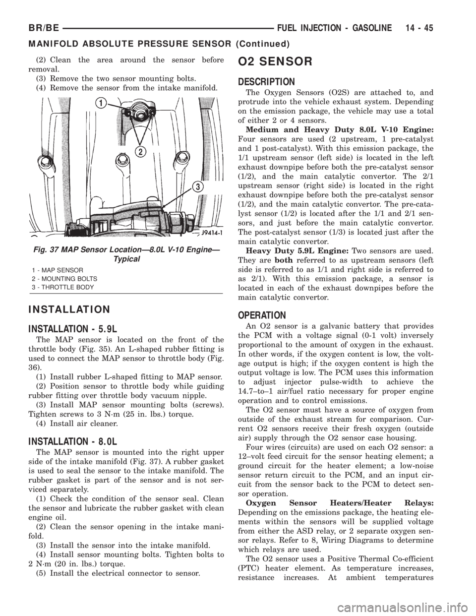
Fig. 37 MAP Sensor LocationÐ8.0L V-10 EngineÐ
Typical
1 - MAP SENSOR
2 - MOUNTING BOLTS
3 - THROTTLE BODY
BR/BEFUEL INJECTION - GASOLINE 14 - 45
MANIFOLD ABSOLUTE PRESSURE SENSOR (Continued)
Page 2141 of 2255
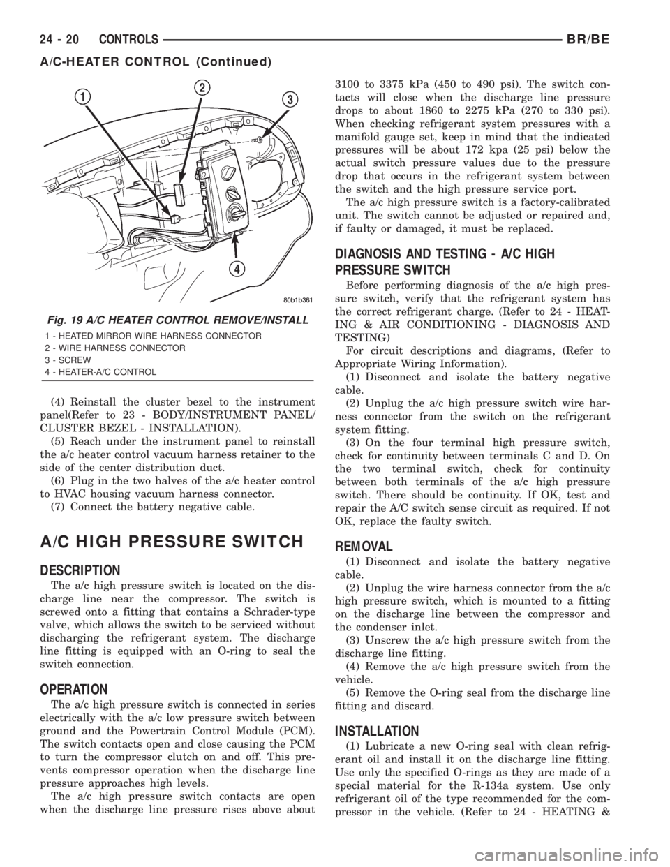
(4) Reinstall the cluster bezel to the instrument
panel(Refer to 23 - BODY/INSTRUMENT PANEL/
CLUSTER BEZEL - INSTALLATION).
(5) Reach under the instrument panel to reinstall
the a/c heater control vacuum harness retainer to the
side of the center distribution duct.
(6) Plug in the two halves of the a/c heater control
to HVAC housing vacuum harness connector.
(7) Connect the battery negative cable.
A/C HIGH PRESSURE SWITCH
DESCRIPTION
The a/c high pressure switch is located on the dis-
charge line near the compressor. The switch is
screwed onto a fitting that contains a Schrader-type
valve, which allows the switch to be serviced without
discharging the refrigerant system. The discharge
line fitting is equipped with an O-ring to seal the
switch connection.
OPERATION
The a/c high pressure switch is connected in series
electrically with the a/c low pressure switch between
ground and the Powertrain Control Module (PCM).
The switch contacts open and close causing the PCM
to turn the compressor clutch on and off. This pre-
vents compressor operation when the discharge line
pressure approaches high levels.
The a/c high pressure switch contacts are open
when the discharge line pressure rises above about3100 to 3375 kPa (450 to 490 psi). The switch con-
tacts will close when the discharge line pressure
drops to about 1860 to 2275 kPa (270 to 330 psi).
When checking refrigerant system pressures with a
manifold gauge set, keep in mind that the indicated
pressures will be about 172 kpa (25 psi) below the
actual switch pressure values due to the pressure
drop that occurs in the refrigerant system between
the switch and the high pressure service port.
The a/c high pressure switch is a factory-calibrated
unit. The switch cannot be adjusted or repaired and,
if faulty or damaged, it must be replaced.
DIAGNOSIS AND TESTING - A/C HIGH
PRESSURE SWITCH
Before performing diagnosis of the a/c high pres-
sure switch, verify that the refrigerant system has
the correct refrigerant charge. (Refer to 24 - HEAT-
ING & AIR CONDITIONING - DIAGNOSIS AND
TESTING)
For circuit descriptions and diagrams, (Refer to
Appropriate Wiring Information).
(1) Disconnect and isolate the battery negative
cable.
(2) Unplug the a/c high pressure switch wire har-
ness connector from the switch on the refrigerant
system fitting.
(3) On the four terminal high pressure switch,
check for continuity between terminals C and D. On
the two terminal switch, check for continuity
between both terminals of the a/c high pressure
switch. There should be continuity. If OK, test and
repair the A/C switch sense circuit as required. If not
OK, replace the faulty switch.
REMOVAL
(1) Disconnect and isolate the battery negative
cable.
(2) Unplug the wire harness connector from the a/c
high pressure switch, which is mounted to a fitting
on the discharge line between the compressor and
the condenser inlet.
(3) Unscrew the a/c high pressure switch from the
discharge line fitting.
(4) Remove the a/c high pressure switch from the
vehicle.
(5) Remove the O-ring seal from the discharge line
fitting and discard.
INSTALLATION
(1) Lubricate a new O-ring seal with clean refrig-
erant oil and install it on the discharge line fitting.
Use only the specified O-rings as they are made of a
special material for the R-134a system. Use only
refrigerant oil of the type recommended for the com-
pressor in the vehicle. (Refer to 24 - HEATING &
Fig. 19 A/C HEATER CONTROL REMOVE/INSTALL
1 - HEATED MIRROR WIRE HARNESS CONNECTOR
2 - WIRE HARNESS CONNECTOR
3 - SCREW
4 - HEATER-A/C CONTROL
24 - 20 CONTROLSBR/BE
A/C-HEATER CONTROL (Continued)
Page 2142 of 2255
AIR CONDITIONING/PLUMBING/REFRIGERANT
OIL - DESCRIPTION)
(2) Install and tighten the high pressure cut-off
switch on the discharge line fitting. The switch
should be hand-tightened onto the discharge line fit-
ting.
(3) Plug the wire harness connector into the high
pressure cut-off switch.
(4) Connect the battery negative cable.
A/C LOW PRESSURE SWITCH
DESCRIPTION
The a/c low pressure switch is located on the top of
the accumulator. The switch is screwed onto an accu-
mulator fitting that contains a Schrader-type valve,
which allows the switch to be serviced without dis-
charging the refrigerant system. The accumulator fit-
ting is equipped with an O-ring to seal the switch
connection.
OPERATION
The a/c low pressure switch is connected in series
electrically with the a/c high pressure switch and the
a/c heater control, between ground and the Power-
train Control Module (PCM). The switch contacts
open and close causing the PCM to turn the compres-
sor clutch on and off. This regulates the refrigerant
system pressure and controls evaporator tempera-
ture. Controlling evaporator temperature prevents
condensate water on the evaporator fins from freez-
ing and obstructing air conditioning system air flow.
The a/c low pressure switch contacts are open
when the suction pressure is about 152-165 kPa
(22-24 psi) or lower. The switch contacts will close
when the suction pressure rises to about 255-296 kPa
(37-43 psi) or above. Lower ambient temperatures,
below about -1É C (30É F), will also cause the switch
contacts to open. This is due to the pressure/temper-
ature relationship of the refrigerant in the system.
The a/c low pressure switch is a factory-calibrated
unit. It cannot be adjusted or repaired and, if faulty
or damaged, it must be replaced.
DIAGNOSIS AND TESTING - A/C LOW
PRESSURE SWITCH
Before performing diagnosis of the a/c low pressure
switch, be certain that the switch is properly
installed on the accumulator fitting. If the switch is
too loose it may not open the Schrader-type valve in
the accumulator fitting, which will prevent the
switch from correctly monitoring the refrigerant sys-
tem pressure. Also verify that the refrigerant system
has the correct refrigerant charge. (Refer to 24 -HEATING & AIR CONDITIONING - DIAGNOSIS
AND TESTING - A/C PERFORMANCE)
Remember that lower ambient temperatures, below
about -1É C (30É F), during cold weather will open the
switch contacts and prevent compressor operation
due to the pressure/temperature relationship of the
refrigerant. For circuit descriptions and diagrams,
(Refer to Appropriate Wiring Information).
(1) Disconnect and isolate the battery negative
cable.
(2) Unplug the a/c low pressure switch wire har-
ness connector from the switch on the accumulator
fitting.
(3) Install a jumper wire between the two cavities
of the a/c low pressure switch wire harness connector.
(4) Connect a manifold gauge set to the refrigerant
system service ports. (Refer to 24 - HEATING & AIR
CONDITIONING/PLUMBING - STANDARD PRO-
CEDURE - REFRIGERANT SYSTEM SERVICE
EQUIPMENT)
(5) Connect the battery negative cable.
(6) Place the a/c heater mode control switch knob
in any A/C position and start the engine.
(7) Check for continuity between the two terminals
of the low pressure cycling clutch switch. There
should be continuity with a suction pressure reading
of 296 kPa (43 psi) or above, and no continuity with a
suction pressure reading of 172 kPa (25 psi) or below.
If OK, test and repair the A/C switch sense circuit as
required. If not OK, replace the faulty switch.
REMOVAL
(1) Disconnect and isolate the battery negative
cable.
(2) Unplug the wire harness connector from the a/c
low pressure switch on the top of the accumulator
(Fig. 20).
(3) Unscrew the a/c low pressure switch from the
fitting on the top of the accumulator.
(4) Remove the O-ring seal from the accumulator
fitting and discard.
INSTALLATION
(1) Lubricate a new O-ring seal with clean refrig-
erant oil and install it on the accumulator fitting.
Use only the specified O-rings as they are made of a
special material for the R-134a system. Use only
refrigerant oil of the type recommended for the com-
pressor in the vehicle. (Refer to 24 - HEATING &
AIR CONDITIONING/PLUMBING/REFRIGERANT
OIL - DESCRIPTION)
(2) Install and tighten the a/c low pressure switch
on the accumulator fitting. The switch should be
hand-tightened onto the accumulator fitting.
(3) Plug the wire harness connector into the a/c
low pressure switch.
BR/BECONTROLS 24 - 21
A/C HIGH PRESSURE SWITCH (Continued)