leak detector DODGE RAM 2003 Service Repair Manual
[x] Cancel search | Manufacturer: DODGE, Model Year: 2003, Model line: RAM, Model: DODGE RAM 2003Pages: 2895, PDF Size: 83.15 MB
Page 2807 of 2895
STANDARD PROCEDURE
STANDARD PROCEDURE - REFRIGERANT
SYSTEM EVACUATE...................51
STANDARD PROCEDURE- REFRIGERANT
RECOVERY..........................52
STANDARD PROCEDURE- REFRIGERANT
SYSTEM CHARGE.....................52
REFRIGERANT LINE COUPLER
DESCRIPTION.........................52OPERATION...........................52
REMOVAL.............................52
INSTALLATION.........................53
REFRIGERANT OIL
DESCRIPTION.........................54
OPERATION...........................54
STANDARD PROCEDURE - REFRIGERANT
OIL LEVEL...........................54
PLUMBING
DESCRIPTION - REFRIGERANT LINE
The refrigerant lines and hoses are used to carry
the refrigerant between the various air conditioning
system components. A barrier hose design with a
nylon tube, which is sandwiched between rubber lay-
ers, is used for the R-134a air conditioning system on
this vehicle. This nylon tube helps to further contain
the R-134a refrigerant, which has a smaller molecu-
lar structure than R-12 refrigerant. The ends of the
refrigerant hoses are made from lightweight alumi-
num or steel, and commonly use braze-less fittings.
Any kinks or sharp bends in the refrigerant plumb-
ing will reduce the capacity of the entire air condi-
tioning system. Kinks and sharp bends reduce the
flow of refrigerant in the system. A good rule for the
flexible hose refrigerant lines is to keep the radius of
all bends at least ten times the diameter of the hose.
In addition, the flexible hose refrigerant lines should
be routed so they are at least 80 millimeters (3
inches) from an exhaust manifold.
OPERATION- REFRIGERANT LINES
High pressures are produced in the refrigerant sys-
tem when the air conditioning compressor is operat-
ing. Extreme care must be exercised to make sure
that each of the refrigerant system connections is
pressure-tight and leak free. It is a good practice to
inspect all flexible hose refrigerant lines at least once
a year to make sure they are in good condition and
properly routed.
The refrigerant lines and hoses are coupled with
other components of the HVAC system with either 3
O-ring spring lock couplings or dual axes seals.
The refrigerant lines and hoses cannot be repaired
and, if faulty or damaged, they must be replaced.
WARNING
SERVICE WARNINGS
WARNING: THE AIR CONDITIONING SYSTEM CON-
TAINS REFRIGERANT UNDER HIGH PRESSURE.
SEVERE PERSONAL INJURY MAY RESULT FROM
IMPROPER SERVICE PROCEDURES. REPAIRS
SHOULD ONLY BE PERFORMED BY QUALIFIED
SERVICE PERSONNEL.
AVOID BREATHING THE REFRIGERANT AND
REFRIGERANT OIL VAPOR OR MIST. EXPOSURE
MAY IRRITATE THE EYES, NOSE, AND/OR THROAT.
WEAR EYE PROTECTION WHEN SERVICING THE
AIR CONDITIONING REFRIGERANT SYSTEM. SERI-
OUS EYE INJURY CAN RESULT FROM DIRECT
CONTACT WITH THE REFRIGERANT. IF EYE CON-
TACT OCCURS, SEEK MEDICAL ATTENTION IMME-
DIATELY.
DO NOT EXPOSE THE REFRIGERANT TO OPEN
FLAME. POISONOUS GAS IS CREATED WHEN
REFRIGERANT IS BURNED. AN ELECTRONIC LEAK
DETECTOR IS RECOMMENDED.
IF ACCIDENTAL SYSTEM DISCHARGE OCCURS,
VENTILATE THE WORK AREA BEFORE RESUMING
SERVICE. LARGE AMOUNTS OF REFRIGERANT
RELEASED IN A CLOSED WORK AREA WILL DIS-
PLACE THE OXYGEN AND CAUSE SUFFOCATION.
THE EVAPORATION RATE OF R-134a REFRIGER-
ANT AT AVERAGE TEMPERATURE AND ALTITUDE
IS EXTREMELY HIGH. AS A RESULT, ANYTHING
THAT COMES IN CONTACT WITH THE REFRIGER-
ANT WILL FREEZE. ALWAYS PROTECT THE SKIN
OR DELICATE OBJECTS FROM DIRECT CONTACT
WITH THE REFRIGERANT.
THE R-134a SERVICE EQUIPMENT OR THE VEHI-
CLE REFRIGERANT SYSTEM SHOULD NOT BE
PRESSURE TESTED OR LEAK TESTED WITH COM-
PRESSED AIR. SOME MIXTURES OF AIR AND
R-134a HAVE BEEN SHOWN TO BE COMBUSTIBLE
AT ELEVATED PRESSURES. THESE MIXTURES ARE
POTENTIALLY DANGEROUS, AND MAY RESULT IN
FIRE OR EXPLOSION CAUSING INJURY OR PROP-
ERTY DAMAGE.
24 - 32 PLUMBINGDR
Page 2826 of 2895
small amount of R-12 added to an R-134a refrigerant
system will cause compressor failure, refrigerant oil
sludge or poor air conditioning system performance.
In addition, the PolyAlkylene Glycol (PAG) synthetic
refrigerant oils used in an R-134a refrigerant system
are not compatible with the mineral-based refriger-
ant oils used in an R-12 refrigerant system.
R-134a refrigerant system service ports, service
tool couplers and refrigerant dispensing bottles have
all been designed with unique fittings to ensure that
an R-134a system is not accidentally contaminated
with the wrong refrigerant (R-12). There are also
labels posted in the engine compartment of the vehi-
cle and on the compressor identifying to service tech-
nicians that the air conditioning system is equipped
with R-134a.
DIAGNOSIS AND TESTING- REFRIGERANT
SYSTEM LEAKS
WARNING: (Refer to 24 - HEATING & AIR CONDI-
TIONING/PLUMBING - WARNING) and (Refer to 24 -
HEATING & AIR CONDITIONING/PLUMBING - CAU-
TION).
If the air conditioning system does not cool prop-
erly, the A/C system performance should be tested.
See A/C Performance in the Diagnosis and Testing
section of this group for the procedures. If the A/C
system refrigerant fill is found to be low or if the sys-
tem is empty; a leak at a refrigerant line, connector
fitting, component, or component seal is likely.
An electronic leak detector designed for R-134a
refrigerant, or a fluorescent R-134a leak detection
dye and a black light are recommended for locating
and confirming refrigerant system leaks. Refer to the
operating instructions supplied by the equipment
manufacturer for the proper care and use of this
equipment.
An oily residue on or near refrigerant system lines,
connector fittings, components, or component seals
can indicate the general location of a possible refrig-
erant leak. However, the exact leak location should
be confirmed with an electronic leak detector prior to
component repair or replacement.
To detect a leak in the refrigerant system with an
electronic leak detector, perform one of the following
procedures:
SYSTEM EMPTY
(1) Evacuate the refrigerant system (Refer to 24 -
HEATING & AIR CONDITIONING/PLUMBING/RE-
FRIGERANT - STANDARD PROCEDURE).
(2) Connect and dispense 0.283 kilograms (0.625
pounds or 10 ounces) of R-134a refrigerant into the
evacuated refrigerant system (Refer to 24 - HEAT-ING & AIR CONDITIONING/PLUMBING/REFRIG-
ERANT - STANDARD PROCEDURE).
(3) Position the vehicle in a wind-free work area.
This will aid in detecting small leaks.
(4) With the engine not running, use a electronic
R-134a leak detector and search for leaks. Because
R-134a refrigerant is heavier than air, the leak detec-
tor probe should be moved slowly along the bottom
side of all refrigerant lines, connector fittings and
components.
(5) To inspect the evaporator coil for leaks, insert
the electronic leak detector probe into the center
instrument panel outlet and the floor duct outlet. Set
the blower motor switch to the lowest speed position,
and the mode control switch in the recirculation
mode (Max-A/C).
SYSTEM LOW
(1) Position the vehicle in a wind-free work area.
This will aid in detecting small leaks.
(2) Bring the refrigerant system up to operating
temperature and pressure. This is done by allowing
the engine to run with the air conditioning system
turned on for five minutes.
(3) With the engine not running, use a electronic
R-134a leak detector and search for leaks. Because
R-134a refrigerant is heavier than air, the leak detec-
tor probe should be moved slowly along the bottom
side of all refrigerant lines, connector fittings and
components.
(4) To inspect the evaporator coil for leaks, insert
the electronic leak detector probe into the center
instrument panel outlet and the floor duct outlet. Set
the blower motor switch to the lowest speed position,
and the mode control switch in the recirculation
mode (Max-A/C).
STANDARD PROCEDURE
STANDARD PROCEDURE - REFRIGERANT
SYSTEM EVACUATE
WARNING: (Refer to 24 - HEATING & AIR CONDI-
TIONING/PLUMBING - WARNING) AND (Refer to 24 -
HEATING & AIR CONDITIONING/PLUMBING - CAU-
TION) BEFORE PERFORMING THE FOLLOWING
OPERATION.
If the refrigerant system has been open to the
atmosphere, it must be evacuated before the system
can be charged. If moisture and air enters the system
and becomes mixed with the refrigerant, the com-
pressor head pressure will rise above acceptable
operating levels. This will reduce the performance of
the air conditioner and could damage the compressor.
Evacuating the refrigerant system will remove the
DRPLUMBING 24 - 51
REFRIGERANT (Continued)
Page 2843 of 2895
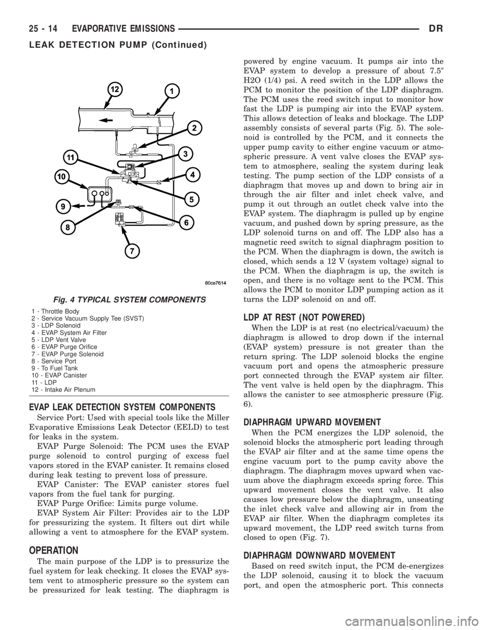
EVAP LEAK DETECTION SYSTEM COMPONENTS
Service Port: Used with special tools like the Miller
Evaporative Emissions Leak Detector (EELD) to test
for leaks in the system.
EVAP Purge Solenoid: The PCM uses the EVAP
purge solenoid to control purging of excess fuel
vapors stored in the EVAP canister. It remains closed
during leak testing to prevent loss of pressure.
EVAP Canister: The EVAP canister stores fuel
vapors from the fuel tank for purging.
EVAP Purge Orifice: Limits purge volume.
EVAP System Air Filter: Provides air to the LDP
for pressurizing the system. It filters out dirt while
allowing a vent to atmosphere for the EVAP system.
OPERATION
The main purpose of the LDP is to pressurize the
fuel system for leak checking. It closes the EVAP sys-
tem vent to atmospheric pressure so the system can
be pressurized for leak testing. The diaphragm ispowered by engine vacuum. It pumps air into the
EVAP system to develop a pressure of about 7.59
H2O (1/4) psi. A reed switch in the LDP allows the
PCM to monitor the position of the LDP diaphragm.
The PCM uses the reed switch input to monitor how
fast the LDP is pumping air into the EVAP system.
This allows detection of leaks and blockage. The LDP
assembly consists of several parts (Fig. 5). The sole-
noid is controlled by the PCM, and it connects the
upper pump cavity to either engine vacuum or atmo-
spheric pressure. A vent valve closes the EVAP sys-
tem to atmosphere, sealing the system during leak
testing. The pump section of the LDP consists of a
diaphragm that moves up and down to bring air in
through the air filter and inlet check valve, and
pump it out through an outlet check valve into the
EVAP system. The diaphragm is pulled up by engine
vacuum, and pushed down by spring pressure, as the
LDP solenoid turns on and off. The LDP also has a
magnetic reed switch to signal diaphragm position to
the PCM. When the diaphragm is down, the switch is
closed, which sends a 12 V (system voltage) signal to
the PCM. When the diaphragm is up, the switch is
open, and there is no voltage sent to the PCM. This
allows the PCM to monitor LDP pumping action as it
turns the LDP solenoid on and off.
LDP AT REST (NOT POWERED)
When the LDP is at rest (no electrical/vacuum) the
diaphragm is allowed to drop down if the internal
(EVAP system) pressure is not greater than the
return spring. The LDP solenoid blocks the engine
vacuum port and opens the atmospheric pressure
port connected through the EVAP system air filter.
The vent valve is held open by the diaphragm. This
allows the canister to see atmospheric pressure (Fig.
6).
DIAPHRAGM UPWARD MOVEMENT
When the PCM energizes the LDP solenoid, the
solenoid blocks the atmospheric port leading through
the EVAP air filter and at the same time opens the
engine vacuum port to the pump cavity above the
diaphragm. The diaphragm moves upward when vac-
uum above the diaphragm exceeds spring force. This
upward movement closes the vent valve. It also
causes low pressure below the diaphragm, unseating
the inlet check valve and allowing air in from the
EVAP air filter. When the diaphragm completes its
upward movement, the LDP reed switch turns from
closed to open (Fig. 7).
DIAPHRAGM DOWNWARD MOVEMENT
Based on reed switch input, the PCM de-energizes
the LDP solenoid, causing it to block the vacuum
port, and open the atmospheric port. This connects
Fig. 4 TYPICAL SYSTEM COMPONENTS
1 - Throttle Body
2 - Service Vacuum Supply Tee (SVST)
3 - LDP Solenoid
4 - EVAP System Air Filter
5 - LDP Vent Valve
6 - EVAP Purge Orifice
7 - EVAP Purge Solenoid
8 - Service Port
9 - To Fuel Tank
10 - EVAP Canister
11 - LDP
12 - Intake Air Plenum
25 - 14 EVAPORATIVE EMISSIONSDR
LEAK DETECTION PUMP (Continued)