remote control DODGE RAM 2003 Service Repair Manual
[x] Cancel search | Manufacturer: DODGE, Model Year: 2003, Model line: RAM, Model: DODGE RAM 2003Pages: 2895, PDF Size: 83.15 MB
Page 373 of 2895
INSTALLATION
BED TO CAB
(1) Install the ground strap and retaining bolts.
Tighten to 5 N´m (45 in. lbs.).
(2) Connect the battery negative cable.
ENGINE TO HEAT SHIELD
(1) Install the retaining nut and ground strap to
the plenum. Tighten to 8 N´m (70 in. lbs.).
(2) Install the retaining bolt and ground strap to
the engine cylinder heads. Tighten to 12 N´m (106 in.
lbs.).
(3) Connect the battery negative cable.
REMOTE SWITCHES
DESCRIPTION
A remote radio control switch option is available on
some models. Two rocker-type switches are mounted
on the back (instrument panel side) of the steering
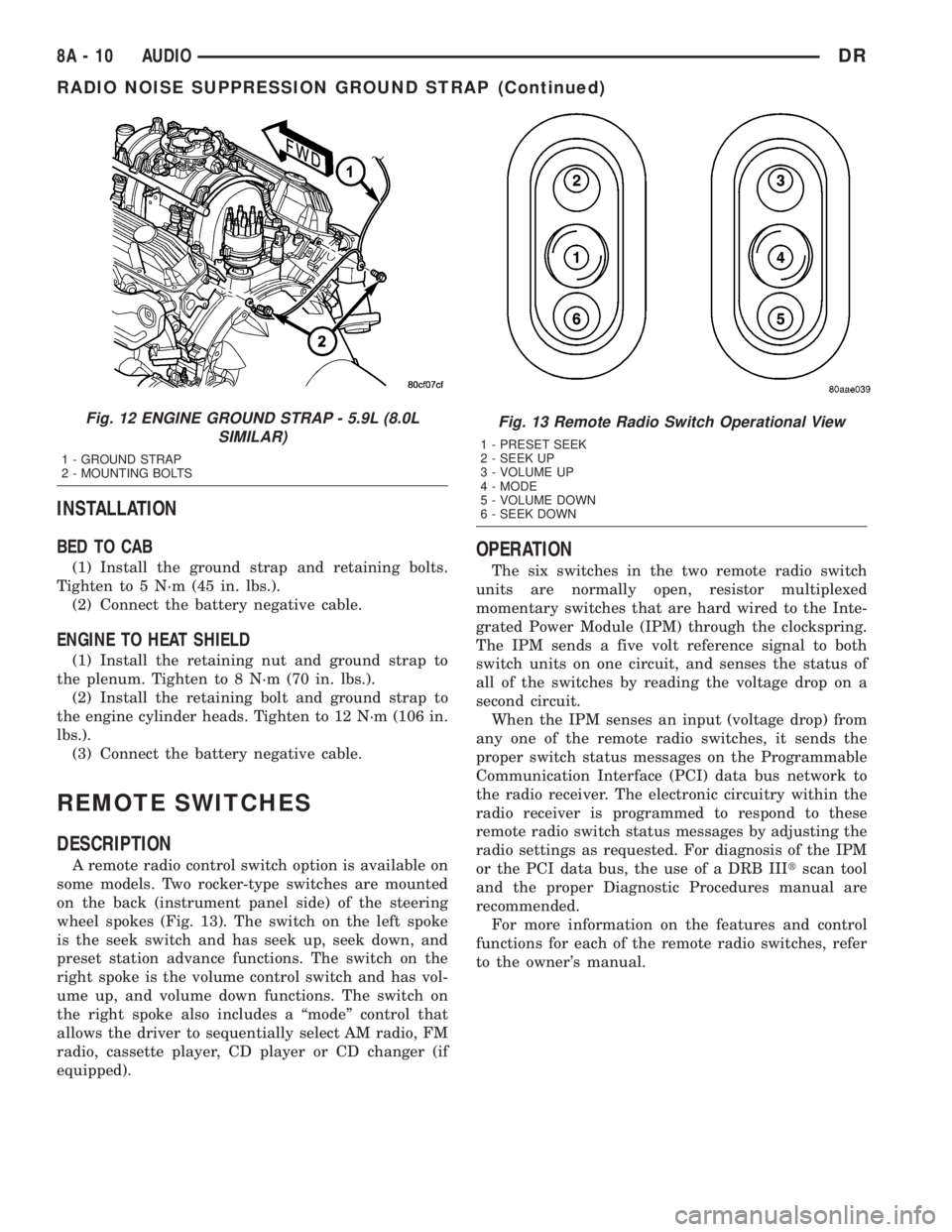
wheel spokes (Fig. 13). The switch on the left spoke
is the seek switch and has seek up, seek down, and
preset station advance functions. The switch on the
right spoke is the volume control switch and has vol-
ume up, and volume down functions. The switch on
the right spoke also includes a ªmodeº control that
allows the driver to sequentially select AM radio, FM
radio, cassette player, CD player or CD changer (if
equipped).
OPERATION
The six switches in the two remote radio switch
units are normally open, resistor multiplexed
momentary switches that are hard wired to the Inte-
grated Power Module (IPM) through the clockspring.
The IPM sends a five volt reference signal to both
switch units on one circuit, and senses the status of
all of the switches by reading the voltage drop on a
second circuit.
When the IPM senses an input (voltage drop) from
any one of the remote radio switches, it sends the
proper switch status messages on the Programmable
Communication Interface (PCI) data bus network to
the radio receiver. The electronic circuitry within the
radio receiver is programmed to respond to these
remote radio switch status messages by adjusting the
radio settings as requested. For diagnosis of the IPM
or the PCI data bus, the use of a DRB IIItscan tool
and the proper Diagnostic Procedures manual are
recommended.
For more information on the features and control
functions for each of the remote radio switches, refer
to the owner's manual.
Fig. 12 ENGINE GROUND STRAP - 5.9L (8.0L
SIMILAR)
1 - GROUND STRAP
2 - MOUNTING BOLTS
Fig. 13 Remote Radio Switch Operational View
1 - PRESET SEEK
2 - SEEK UP
3 - VOLUME UP
4 - MODE
5 - VOLUME DOWN
6 - SEEK DOWN
8A - 10 AUDIODR
RADIO NOISE SUPPRESSION GROUND STRAP (Continued)
Page 374 of 2895
DIAGNOSIS AND TESTING - REMOTE
SWITCHES
Any diagnosis of the Audio system should
begin with the use of the DRB IIItdiagnostic
tool. For information on the use of the DRB
IIIt, refer to the appropriate Diagnostic Service
Manual.
For complete circuit diagrams, refer to the appro-
priate wiring information. The wiring information
includes wiring diagrams, proper wire and connector
repair procedures, details of wire harness routing
and retention, connector pin-out information and
location views for the various wire harness connec-
tors, splices and grounds.
WARNING: DISABLE THE AIRBAG SYSTEM
BEFORE ATTEMPTING ANY STEERING WHEEL,
STEERING COLUMN, SEAT BELT TENSIONER, SIDE
AIRBAG, OR INSTRUMENT PANEL COMPONENT
DIAGNOSIS OR SERVICE. DISCONNECT AND ISO-
LATE THE BATTERY NEGATIVE (GROUND) CABLE,
THEN WAIT TWO MINUTES FOR THE AIRBAG SYS-
TEM CAPACITOR TO DISCHARGE BEFORE PER-
FORMING FURTHER DIAGNOSIS OR SERVICE. THIS
IS THE ONLY SURE WAY TO DISABLE THE AIRBAG
SYSTEM. FAILURE TO TAKE THE PROPER PRE-
CAUTIONS COULD RESULT IN ACCIDENTAL AIR-
BAG DEPLOYMENT AND POSSIBLE PERSONAL
INJURY.
(1) Disconnect and isolate the battery negative
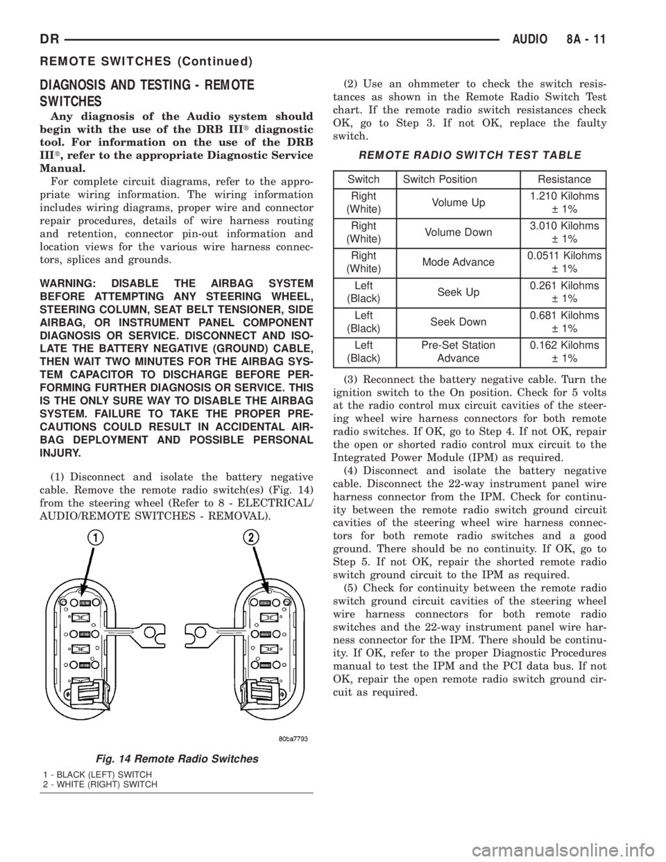
cable. Remove the remote radio switch(es) (Fig. 14)
from the steering wheel (Refer to 8 - ELECTRICAL/
AUDIO/REMOTE SWITCHES - REMOVAL).(2) Use an ohmmeter to check the switch resis-
tances as shown in the Remote Radio Switch Test
chart. If the remote radio switch resistances check
OK, go to Step 3. If not OK, replace the faulty
switch.
REMOTE RADIO SWITCH TEST TABLE
Switch Switch Position Resistance
Right
(White)Volume Up1.210 Kilohms
1%
Right
(White)Volume Down3.010 Kilohms
1%
Right
(White)Mode Advance0.0511 Kilohms
1%
Left
(Black)Seek Up0.261 Kilohms
1%
Left
(Black)Seek Down0.681 Kilohms
1%
Left
(Black)Pre-Set Station
Advance0.162 Kilohms
1%
(3) Reconnect the battery negative cable. Turn the
ignition switch to the On position. Check for 5 volts
at the radio control mux circuit cavities of the steer-
ing wheel wire harness connectors for both remote
radio switches. If OK, go to Step 4. If not OK, repair
the open or shorted radio control mux circuit to the
Integrated Power Module (IPM) as required.
(4) Disconnect and isolate the battery negative
cable. Disconnect the 22-way instrument panel wire
harness connector from the IPM. Check for continu-
ity between the remote radio switch ground circuit
cavities of the steering wheel wire harness connec-
tors for both remote radio switches and a good
ground. There should be no continuity. If OK, go to
Step 5. If not OK, repair the shorted remote radio
switch ground circuit to the IPM as required.
(5) Check for continuity between the remote radio
switch ground circuit cavities of the steering wheel
wire harness connectors for both remote radio
switches and the 22-way instrument panel wire har-
ness connector for the IPM. There should be continu-
ity. If OK, refer to the proper Diagnostic Procedures
manual to test the IPM and the PCI data bus. If not
OK, repair the open remote radio switch ground cir-
cuit as required.
Fig. 14 Remote Radio Switches
1 - BLACK (LEFT) SWITCH
2 - WHITE (RIGHT) SWITCH
DRAUDIO 8A - 11
REMOTE SWITCHES (Continued)
Page 375 of 2895
REMOVAL
WARNING: DISABLE THE AIRBAG SYSTEM
BEFORE ATTEMPTING ANY STEERING WHEEL,
STEERING COLUMN, SEAT BELT TENSIONER, SIDE
AIRBAG, OR INSTRUMENT PANEL COMPONENT
DIAGNOSIS OR SERVICE. DISCONNECT AND ISO-
LATE THE BATTERY NEGATIVE (GROUND) CABLE,
THEN WAIT TWO MINUTES FOR THE AIRBAG SYS-
TEM CAPACITOR TO DISCHARGE BEFORE PER-
FORMING FURTHER DIAGNOSIS OR SERVICE. THIS
IS THE ONLY SURE WAY TO DISABLE THE AIRBAG
SYSTEM. FAILURE TO TAKE THE PROPER PRE-
CAUTIONS COULD RESULT IN ACCIDENTAL AIR-
BAG DEPLOYMENT AND POSSIBLE PERSONAL
INJURY.
(1) Disconnect and isolate the battery negative
cable.
(2) Remove the driver airbag from the vehicle
(Refer to 8 - ELECTRICAL/RESTRAINTS/DRIVER
AIRBAG - REMOVAL).
(3) Remove the speed control switches (Refer to 8 -
ELECTRICAL/SPEED CONTROL/SWITCH -
REMOVAL).
(4) Unplug the wire harness connector from the
remote radio switch(es).
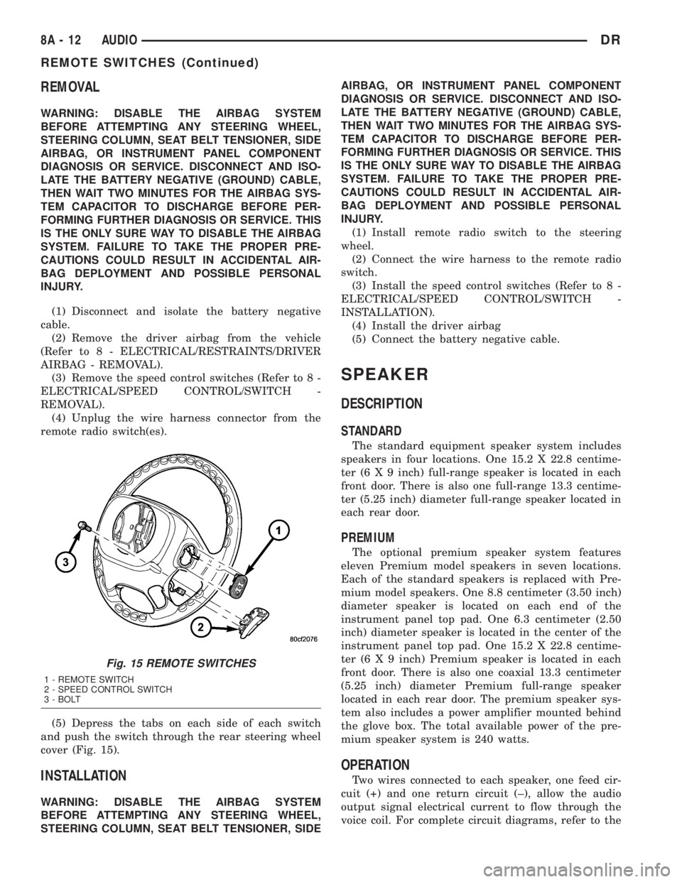
(5) Depress the tabs on each side of each switch
and push the switch through the rear steering wheel
cover (Fig. 15).
INSTALLATION
WARNING: DISABLE THE AIRBAG SYSTEM
BEFORE ATTEMPTING ANY STEERING WHEEL,
STEERING COLUMN, SEAT BELT TENSIONER, SIDEAIRBAG, OR INSTRUMENT PANEL COMPONENT
DIAGNOSIS OR SERVICE. DISCONNECT AND ISO-
LATE THE BATTERY NEGATIVE (GROUND) CABLE,
THEN WAIT TWO MINUTES FOR THE AIRBAG SYS-
TEM CAPACITOR TO DISCHARGE BEFORE PER-
FORMING FURTHER DIAGNOSIS OR SERVICE. THIS
IS THE ONLY SURE WAY TO DISABLE THE AIRBAG
SYSTEM. FAILURE TO TAKE THE PROPER PRE-
CAUTIONS COULD RESULT IN ACCIDENTAL AIR-
BAG DEPLOYMENT AND POSSIBLE PERSONAL
INJURY.
(1) Install remote radio switch to the steering
wheel.
(2) Connect the wire harness to the remote radio
switch.
(3) Install the speed control switches (Refer to 8 -
ELECTRICAL/SPEED CONTROL/SWITCH -
INSTALLATION).
(4) Install the driver airbag
(5) Connect the battery negative cable.
SPEAKER
DESCRIPTION
STANDARD
The standard equipment speaker system includes
speakers in four locations. One 15.2 X 22.8 centime-
ter (6 X 9 inch) full-range speaker is located in each
front door. There is also one full-range 13.3 centime-
ter (5.25 inch) diameter full-range speaker located in
each rear door.
PREMIUM
The optional premium speaker system features
eleven Premium model speakers in seven locations.
Each of the standard speakers is replaced with Pre-
mium model speakers. One 8.8 centimeter (3.50 inch)
diameter speaker is located on each end of the
instrument panel top pad. One 6.3 centimeter (2.50
inch) diameter speaker is located in the center of the
instrument panel top pad. One 15.2 X 22.8 centime-
ter (6 X 9 inch) Premium speaker is located in each
front door. There is also one coaxial 13.3 centimeter
(5.25 inch) diameter Premium full-range speaker
located in each rear door. The premium speaker sys-
tem also includes a power amplifier mounted behind
the glove box. The total available power of the pre-
mium speaker system is 240 watts.
OPERATION
Two wires connected to each speaker, one feed cir-
cuit (+) and one return circuit (±), allow the audio
output signal electrical current to flow through the
voice coil. For complete circuit diagrams, refer to the
Fig. 15 REMOTE SWITCHES
1 - REMOTE SWITCH
2 - SPEED CONTROL SWITCH
3 - BOLT
8A - 12 AUDIODR
REMOTE SWITCHES (Continued)
Page 459 of 2895
The Auto Shutdown (ASD) relay provides battery
voltage to each ignition coil.
The ignition system consists of:
²6 Spark Plugs
²6 Separate Ignition Coils
²2 Knock Sensors
²Powertrain Control Module (PCM)
²Also to be considered part of the ignition system
are certain inputs from the Crankshaft Position,
Camshaft Position, Throttle Position, 2 knock and
MAP Sensors
4.7L V-8 ENGINE
The 4.7L V-8 engine uses a separate ignition coil for
each cylinder. The one-piece coil bolts directly to the
cylinder head. Rubber boots seal the secondary termi-
nal ends of the coils to the top of all 8 spark plugs. A
separate electrical connector is used for each coil.
Because of coil design, spark plug cables (second-
ary cables) are not used. A distributor is not used
with the 4.7L engine.
Two knock sensors (one for each cylinder bank) are
used to help control spark knock.
The Auto Shutdown (ASD) relay provides battery
voltage to each ignition coil.
The ignition system consists of:
²8 Spark Plugs
²8 Separate Ignition Coils
²2 Knock Sensors
²Powertrain Control Module (PCM)
²Also to be considered part of the ignition system
are certain inputs from the Crankshaft Position,
Camshaft Position, Throttle Position, 2 knock and
MAP Sensors
5.7L V-8 ENGINE
For additional information, also refer to Igni-
tion Coil Description and Operation.
The 5.7L V-8 engine is equipped with 16 spark
plugs. Two plugs are used for each cylinder. The 5.7L
is also equipped with 8 separate and independent
ignition coils. The one-piece coil bolts directly to the
cylinder head cover and attaches the coils secondary
output terminal directly to a spark plug using a rub-
ber boot seal. Each coil is also equipped with a sec-
ond output terminal. This second terminal connects a
conventional spark plug cable directly to a spark
plug on the opposite cylinder bank. A separate pri-
mary electrical connector is used for each coil.
Eight conventional spark plug cables are used with
the 5.7L. These cables connect a coil on one cylinder
bank, directly to a spark plug on the opposite cylin-
der bank. The cables are placed and routed in a spe-
cial plastic loom to keep them separated. This loom is
clipped to the intake manifold. To prevent a miss-
match of cables, a corresponding spark plug / coil
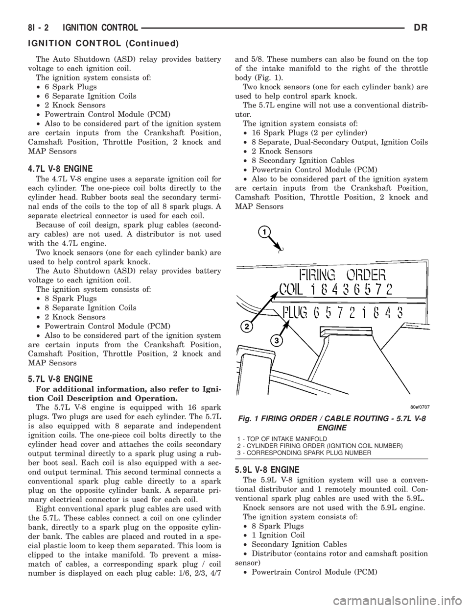
number is displayed on each plug cable: 1/6, 2/3, 4/7and 5/8. These numbers can also be found on the top
of the intake manifold to the right of the throttle
body (Fig. 1).
Two knock sensors (one for each cylinder bank) are
used to help control spark knock.
The 5.7L engine will not use a conventional distrib-
utor.
The ignition system consists of:
²16 Spark Plugs (2 per cylinder)
²
8 Separate, Dual-Secondary Output, Ignition Coils
²2 Knock Sensors
²8 Secondary Ignition Cables
²Powertrain Control Module (PCM)
²Also to be considered part of the ignition system
are certain inputs from the Crankshaft Position,
Camshaft Position, Throttle Position, 2 knock and
MAP Sensors
5.9L V-8 ENGINE
The 5.9L V-8 ignition system will use a conven-
tional distributor and 1 remotely mounted coil. Con-
ventional spark plug cables are used with the 5.9L.
Knock sensors are not used with the 5.9L engine.
The ignition system consists of:
²8 Spark Plugs
²1 Ignition Coil
²Secondary Ignition Cables
²Distributor (contains rotor and camshaft position
sensor)
²Powertrain Control Module (PCM)
Fig. 1 FIRING ORDER / CABLE ROUTING - 5.7L V-8
ENGINE
1 - TOP OF INTAKE MANIFOLD
2 - CYLINDER FIRING ORDER (IGNITION COIL NUMBER)
3 - CORRESPONDING SPARK PLUG NUMBER
8I - 2 IGNITION CONTROLDR
IGNITION CONTROL (Continued)
Page 460 of 2895
²Also to be considered part of the ignition system
are certain inputs from the Crankshaft Position, Cam-
shaft Position, Throttle Position and MAP Sensors
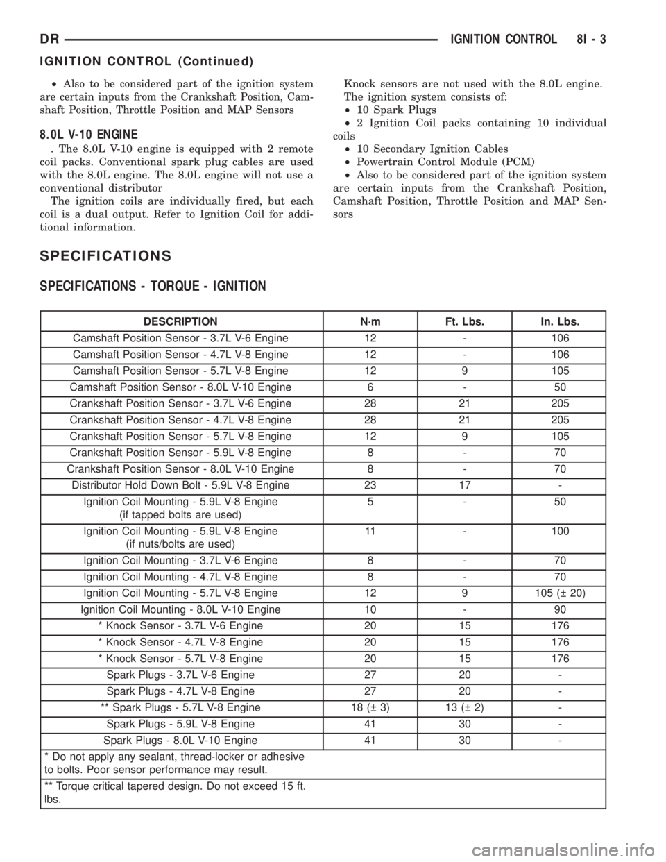
8.0L V-10 ENGINE
. The 8.0L V-10 engine is equipped with 2 remote
coil packs. Conventional spark plug cables are used
with the 8.0L engine. The 8.0L engine will not use a
conventional distributor
The ignition coils are individually fired, but each
coil is a dual output. Refer to Ignition Coil for addi-
tional information.Knock sensors are not used with the 8.0L engine.
The ignition system consists of:
²10 Spark Plugs
²2 Ignition Coil packs containing 10 individual
coils
²10 Secondary Ignition Cables
²Powertrain Control Module (PCM)
²Also to be considered part of the ignition system
are certain inputs from the Crankshaft Position,
Camshaft Position, Throttle Position and MAP Sen-
sors
SPECIFICATIONS
SPECIFICATIONS - TORQUE - IGNITION
DESCRIPTION N´m Ft. Lbs. In. Lbs.
Camshaft Position Sensor - 3.7L V-6 Engine 12 - 106
Camshaft Position Sensor - 4.7L V-8 Engine 12 - 106
Camshaft Position Sensor - 5.7L V-8 Engine 12 9 105
Camshaft Position Sensor - 8.0L V-10 Engine 6 - 50
Crankshaft Position Sensor - 3.7L V-6 Engine 28 21 205
Crankshaft Position Sensor - 4.7L V-8 Engine 28 21 205
Crankshaft Position Sensor - 5.7L V-8 Engine 12 9 105
Crankshaft Position Sensor - 5.9L V-8 Engine 8 - 70
Crankshaft Position Sensor - 8.0L V-10 Engine 8 - 70
Distributor Hold Down Bolt - 5.9L V-8 Engine 23 17 -
Ignition Coil Mounting - 5.9L V-8 Engine
(if tapped bolts are used)5-50
Ignition Coil Mounting - 5.9L V-8 Engine
(if nuts/bolts are used)11 - 100
Ignition Coil Mounting - 3.7L V-6 Engine 8 - 70
Ignition Coil Mounting - 4.7L V-8 Engine 8 - 70
Ignition Coil Mounting - 5.7L V-8 Engine 12 9 105 ( 20)
Ignition Coil Mounting - 8.0L V-10 Engine 10 - 90
* Knock Sensor - 3.7L V-6 Engine 20 15 176
* Knock Sensor - 4.7L V-8 Engine 20 15 176
* Knock Sensor - 5.7L V-8 Engine 20 15 176
Spark Plugs - 3.7L V-6 Engine 27 20 -
Spark Plugs - 4.7L V-8 Engine 27 20 -
** Spark Plugs - 5.7L V-8 Engine 18 ( 3) 13 ( 2) -
Spark Plugs - 5.9L V-8 Engine 41 30 -
Spark Plugs - 8.0L V-10 Engine 41 30 -
* Do not apply any sealant, thread-locker or adhesive
to bolts. Poor sensor performance may result.
** Torque critical tapered design. Do not exceed 15 ft.
lbs.
DRIGNITION CONTROL 8I - 3
IGNITION CONTROL (Continued)
Page 497 of 2895
cluster illumination lamps and provide electronic
headlamp low beam and park lamp request messages
to the Front Control Module (FCM) located on the
Integrated Power Module (IPM) for default exterior
lamp operation. The FCM will also provide default
park lamp and headlamp low beam operation and the
EMIC will turn on the cluster illumination lamps if
there is a failure of the electronic data bus commu-
nication between the EMIC and the FCM.
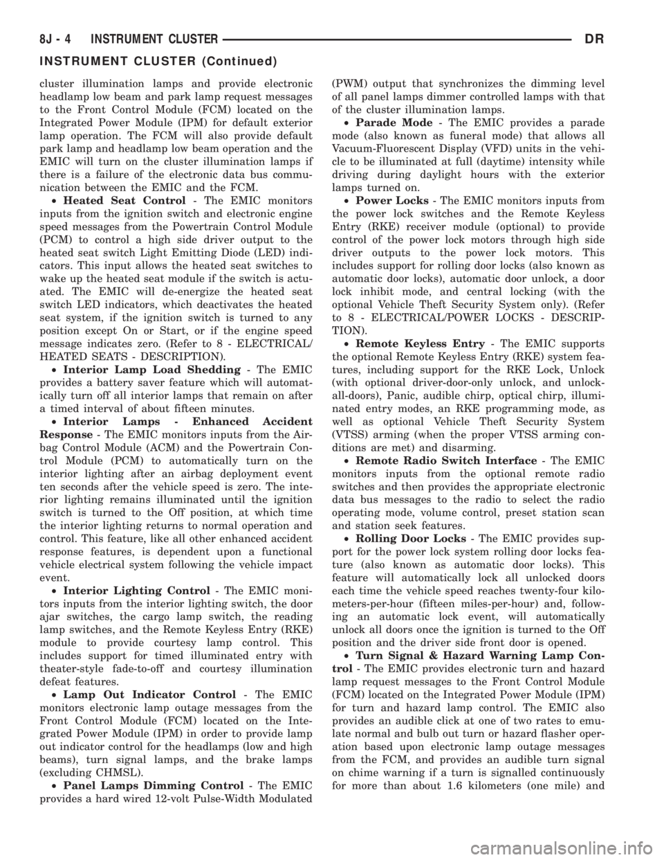
²Heated Seat Control- The EMIC monitors
inputs from the ignition switch and electronic engine
speed messages from the Powertrain Control Module
(PCM) to control a high side driver output to the
heated seat switch Light Emitting Diode (LED) indi-
cators. This input allows the heated seat switches to
wake up the heated seat module if the switch is actu-
ated. The EMIC will de-energize the heated seat
switch LED indicators, which deactivates the heated
seat system, if the ignition switch is turned to any
position except On or Start, or if the engine speed
message indicates zero. (Refer to 8 - ELECTRICAL/
HEATED SEATS - DESCRIPTION).
²Interior Lamp Load Shedding- The EMIC
provides a battery saver feature which will automat-
ically turn off all interior lamps that remain on after
a timed interval of about fifteen minutes.
²Interior Lamps - Enhanced Accident
Response- The EMIC monitors inputs from the Air-
bag Control Module (ACM) and the Powertrain Con-
trol Module (PCM) to automatically turn on the
interior lighting after an airbag deployment event
ten seconds after the vehicle speed is zero. The inte-
rior lighting remains illuminated until the ignition
switch is turned to the Off position, at which time
the interior lighting returns to normal operation and
control. This feature, like all other enhanced accident
response features, is dependent upon a functional
vehicle electrical system following the vehicle impact
event.
²Interior Lighting Control- The EMIC moni-
tors inputs from the interior lighting switch, the door
ajar switches, the cargo lamp switch, the reading
lamp switches, and the Remote Keyless Entry (RKE)
module to provide courtesy lamp control. This
includes support for timed illuminated entry with
theater-style fade-to-off and courtesy illumination
defeat features.
²Lamp Out Indicator Control- The EMIC
monitors electronic lamp outage messages from the
Front Control Module (FCM) located on the Inte-
grated Power Module (IPM) in order to provide lamp
out indicator control for the headlamps (low and high
beams), turn signal lamps, and the brake lamps
(excluding CHMSL).
²Panel Lamps Dimming Control- The EMIC
provides a hard wired 12-volt Pulse-Width Modulated(PWM) output that synchronizes the dimming level
of all panel lamps dimmer controlled lamps with that
of the cluster illumination lamps.
²Parade Mode- The EMIC provides a parade
mode (also known as funeral mode) that allows all
Vacuum-Fluorescent Display (VFD) units in the vehi-
cle to be illuminated at full (daytime) intensity while
driving during daylight hours with the exterior
lamps turned on.
²Power Locks- The EMIC monitors inputs from
the power lock switches and the Remote Keyless
Entry (RKE) receiver module (optional) to provide
control of the power lock motors through high side
driver outputs to the power lock motors. This
includes support for rolling door locks (also known as
automatic door locks), automatic door unlock, a door
lock inhibit mode, and central locking (with the
optional Vehicle Theft Security System only). (Refer
to 8 - ELECTRICAL/POWER LOCKS - DESCRIP-
TION).
²Remote Keyless Entry- The EMIC supports
the optional Remote Keyless Entry (RKE) system fea-
tures, including support for the RKE Lock, Unlock
(with optional driver-door-only unlock, and unlock-
all-doors), Panic, audible chirp, optical chirp, illumi-
nated entry modes, an RKE programming mode, as
well as optional Vehicle Theft Security System
(VTSS) arming (when the proper VTSS arming con-
ditions are met) and disarming.
²Remote Radio Switch Interface- The EMIC
monitors inputs from the optional remote radio
switches and then provides the appropriate electronic
data bus messages to the radio to select the radio
operating mode, volume control, preset station scan
and station seek features.
²Rolling Door Locks- The EMIC provides sup-
port for the power lock system rolling door locks fea-
ture (also known as automatic door locks). This
feature will automatically lock all unlocked doors
each time the vehicle speed reaches twenty-four kilo-
meters-per-hour (fifteen miles-per-hour) and, follow-
ing an automatic lock event, will automatically
unlock all doors once the ignition is turned to the Off
position and the driver side front door is opened.
²Turn Signal & Hazard Warning Lamp Con-
trol- The EMIC provides electronic turn and hazard
lamp request messages to the Front Control Module
(FCM) located on the Integrated Power Module (IPM)
for turn and hazard lamp control. The EMIC also
provides an audible click at one of two rates to emu-
late normal and bulb out turn or hazard flasher oper-
ation based upon electronic lamp outage messages
from the FCM, and provides an audible turn signal
on chime warning if a turn is signalled continuously
for more than about 1.6 kilometers (one mile) and
8J - 4 INSTRUMENT CLUSTERDR
INSTRUMENT CLUSTER (Continued)
Page 498 of 2895
the vehicle speed remains greater than about twenty-
four kilometers-per-hour (fifteen miles-per-hour).
²Vacuum Fluorescent Display Synchroniza-
tion- The EMIC transmits electronic panel lamp
dimming level messages which allows all other elec-
tronic modules on the PCI data bus with Vacuum
Fluorescent Display (VFD) units to coordinate their
illumination intensity with that of the EMIC VFD
units.
²Vehicle Theft Security System- The EMIC
monitors inputs from the door cylinder lock switch-
(es), the door ajar switches, the ignition switch, and
the Remote Keyless Entry (RKE) receiver module,
then provides electronic horn and lighting request
messages to the Front Control Module (FCM) located
on the Integrated Power Module (IPM) for the appro-
priate VTSS alarm output features.
²Wiper/Washer System Control- The EMIC
provides electronic wiper and/or washer request mes-
sages to the Front Control Module (FCM) located on
the Integrated Power Module (IPM) for the appropri-
ate wiper and washer system features. (Refer to 8 -
ELECTRICAL/WIPERS/WASHERS - DESCRIP-
TION).
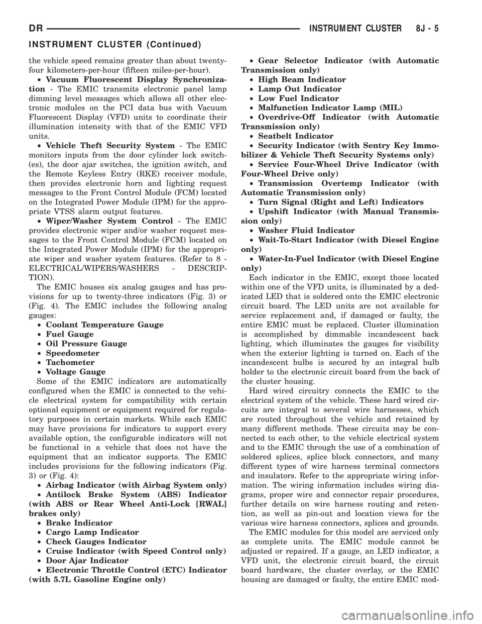
The EMIC houses six analog gauges and has pro-
visions for up to twenty-three indicators (Fig. 3) or
(Fig. 4). The EMIC includes the following analog
gauges:
²Coolant Temperature Gauge
²Fuel Gauge
²Oil Pressure Gauge
²Speedometer
²Tachometer
²Voltage Gauge
Some of the EMIC indicators are automatically
configured when the EMIC is connected to the vehi-
cle electrical system for compatibility with certain
optional equipment or equipment required for regula-
tory purposes in certain markets. While each EMIC
may have provisions for indicators to support every
available option, the configurable indicators will not
be functional in a vehicle that does not have the
equipment that an indicator supports. The EMIC
includes provisions for the following indicators (Fig.
3) or (Fig. 4):
²Airbag Indicator (with Airbag System only)
²Antilock Brake System (ABS) Indicator
(with ABS or Rear Wheel Anti-Lock [RWAL]
brakes only)
²Brake Indicator
²Cargo Lamp Indicator
²Check Gauges Indicator
²Cruise Indicator (with Speed Control only)
²Door Ajar Indicator
²Electronic Throttle Control (ETC) Indicator
(with 5.7L Gasoline Engine only)²Gear Selector Indicator (with Automatic
Transmission only)
²High Beam Indicator
²Lamp Out Indicator
²Low Fuel Indicator
²Malfunction Indicator Lamp (MIL)
²Overdrive-Off Indicator (with Automatic
Transmission only)
²Seatbelt Indicator
²Security Indicator (with Sentry Key Immo-
bilizer & Vehicle Theft Security Systems only)
²Service Four-Wheel Drive Indicator (with
Four-Wheel Drive only)
²Transmission Overtemp Indicator (with
Automatic Transmission only)
²Turn Signal (Right and Left) Indicators
²Upshift Indicator (with Manual Transmis-
sion only)
²Washer Fluid Indicator
²Wait-To-Start Indicator (with Diesel Engine
only)
²Water-In-Fuel Indicator (with Diesel Engine
only)
Each indicator in the EMIC, except those located
within one of the VFD units, is illuminated by a ded-
icated LED that is soldered onto the EMIC electronic
circuit board. The LED units are not available for
service replacement and, if damaged or faulty, the
entire EMIC must be replaced. Cluster illumination
is accomplished by dimmable incandescent back
lighting, which illuminates the gauges for visibility
when the exterior lighting is turned on. Each of the
incandescent bulbs is secured by an integral bulb
holder to the electronic circuit board from the back of
the cluster housing.
Hard wired circuitry connects the EMIC to the
electrical system of the vehicle. These hard wired cir-
cuits are integral to several wire harnesses, which
are routed throughout the vehicle and retained by
many different methods. These circuits may be con-
nected to each other, to the vehicle electrical system
and to the EMIC through the use of a combination of
soldered splices, splice block connectors, and many
different types of wire harness terminal connectors
and insulators. Refer to the appropriate wiring infor-
mation. The wiring information includes wiring dia-
grams, proper wire and connector repair procedures,
further details on wire harness routing and reten-
tion, as well as pin-out and location views for the
various wire harness connectors, splices and grounds.
The EMIC modules for this model are serviced only
as complete units. The EMIC module cannot be
adjusted or repaired. If a gauge, an LED indicator, a
VFD unit, the electronic circuit board, the circuit
board hardware, the cluster overlay, or the EMIC
housing are damaged or faulty, the entire EMIC mod-
DRINSTRUMENT CLUSTER 8J - 5
INSTRUMENT CLUSTER (Continued)
Page 513 of 2895
WARNING: ON VEHICLES EQUIPPED WITH AIR-
BAGS, DISABLE THE SUPPLEMENTAL RESTRAINT
SYSTEM BEFORE ATTEMPTING ANY STEERING
WHEEL, STEERING COLUMN, DRIVER AIRBAG,
PASSENGER AIRBAG, SEAT BELT TENSIONER,
SIDE CURTAIN AIRBAG, OR INSTRUMENT PANEL
COMPONENT DIAGNOSIS OR SERVICE. DISCON-
NECT AND ISOLATE THE BATTERY NEGATIVE
(GROUND) CABLE, THEN WAIT TWO MINUTES FOR
THE SYSTEM CAPACITOR TO DISCHARGE BEFORE
PERFORMING FURTHER DIAGNOSIS OR SERVICE.
THIS IS THE ONLY SURE WAY TO DISABLE THE
SUPPLEMENTAL RESTRAINT SYSTEM. FAILURE TO
TAKE THE PROPER PRECAUTIONS COULD
RESULT IN ACCIDENTAL AIRBAG DEPLOYMENT
AND POSSIBLE PERSONAL INJURY.
INDICATOR ILLUMINATES DURING BULB TEST, BUT DOES
NOT WHEN PARK BRAKE APPLIED
(1) Disconnect and isolate the battery negative
cable. Disconnect the body wire harness connector for
the park brake switch from the switch terminal.
Apply the parking brake. Check for continuity
between the park brake switch terminal and a good
ground. There should be continuity. If OK, go to Step
2. If not OK, replace the faulty park brake switch.
(2) Disconnect the instrument panel wire harness
connector (Connector C1) for the instrument cluster
from the cluster connector receptacle. Check for con-
tinuity between the park brake switch sense circuit
cavities of the body wire harness connector for the
park brake switch and the instrument panel wire
harness connector for the instrument cluster. There
should be continuity. If not OK, repair the open park
brake switch sense circuit between the park brake
switch and the instrument cluster as required.
INDICATOR REMAINS ILLUMINATED - BRAKE SYSTEM
CHECKS OK
(1) Disconnect and isolate the battery negative
cable. Disconnect the body wire harness connector for
the park brake switch from the switch terminal.
Check for continuity between the terminal of the
park brake switch and a good ground. There should
be no continuity with the park brake released, and
continuity with the park brake applied. If OK, go to
Step 2. If not OK, replace the faulty park brake
switch.
(2) Disconnect the instrument panel wire harness
connector (Connector C1) for the instrument cluster
from the cluster connector receptacle. Check for con-
tinuity between the park brake switch sense circuit
cavity of the body wire harness connector for the
park brake switch and a good ground. There should
be no continuity. If not OK, repair the shorted parkbrake switch sense circuit between the park brake
switch and the instrument cluster as required.
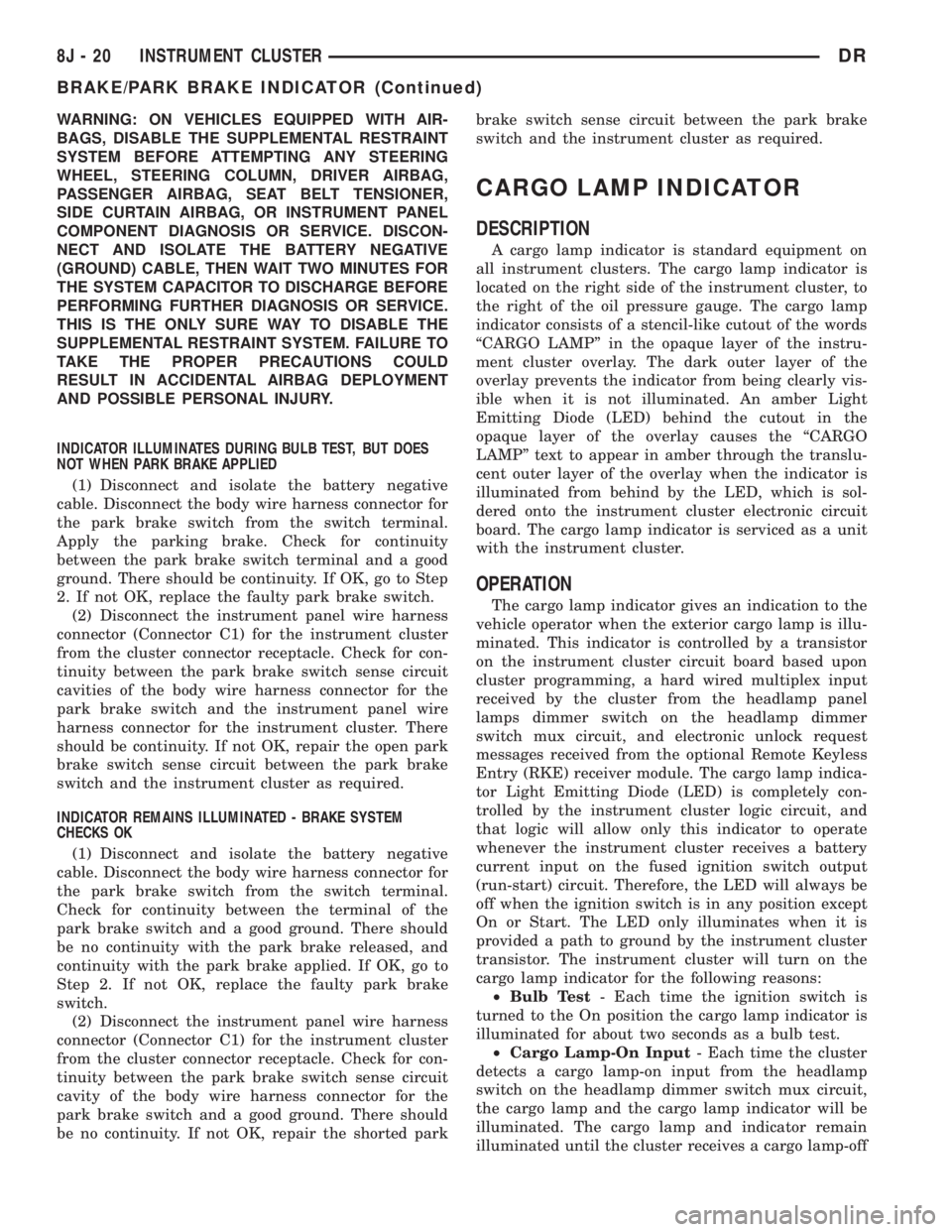
CARGO LAMP INDICATOR
DESCRIPTION
A cargo lamp indicator is standard equipment on
all instrument clusters. The cargo lamp indicator is
located on the right side of the instrument cluster, to
the right of the oil pressure gauge. The cargo lamp
indicator consists of a stencil-like cutout of the words
ªCARGO LAMPº in the opaque layer of the instru-
ment cluster overlay. The dark outer layer of the
overlay prevents the indicator from being clearly vis-
ible when it is not illuminated. An amber Light
Emitting Diode (LED) behind the cutout in the
opaque layer of the overlay causes the ªCARGO
LAMPº text to appear in amber through the translu-
cent outer layer of the overlay when the indicator is
illuminated from behind by the LED, which is sol-
dered onto the instrument cluster electronic circuit
board. The cargo lamp indicator is serviced as a unit
with the instrument cluster.
OPERATION
The cargo lamp indicator gives an indication to the
vehicle operator when the exterior cargo lamp is illu-
minated. This indicator is controlled by a transistor
on the instrument cluster circuit board based upon
cluster programming, a hard wired multiplex input
received by the cluster from the headlamp panel
lamps dimmer switch on the headlamp dimmer
switch mux circuit, and electronic unlock request
messages received from the optional Remote Keyless
Entry (RKE) receiver module. The cargo lamp indica-
tor Light Emitting Diode (LED) is completely con-
trolled by the instrument cluster logic circuit, and
that logic will allow only this indicator to operate
whenever the instrument cluster receives a battery
current input on the fused ignition switch output
(run-start) circuit. Therefore, the LED will always be
off when the ignition switch is in any position except
On or Start. The LED only illuminates when it is
provided a path to ground by the instrument cluster
transistor. The instrument cluster will turn on the
cargo lamp indicator for the following reasons:
²Bulb Test- Each time the ignition switch is
turned to the On position the cargo lamp indicator is
illuminated for about two seconds as a bulb test.
²Cargo Lamp-On Input- Each time the cluster
detects a cargo lamp-on input from the headlamp
switch on the headlamp dimmer switch mux circuit,
the cargo lamp and the cargo lamp indicator will be
illuminated. The cargo lamp and indicator remain
illuminated until the cluster receives a cargo lamp-off
8J - 20 INSTRUMENT CLUSTERDR
BRAKE/PARK BRAKE INDICATOR (Continued)
Page 528 of 2895
nated. A red Light Emitting Diode (LED) behind the
cutout in the opaque layer of the overlay causes the
indicator to appear in red through the translucent
outer layer of the overlay when it is illuminated from
behind by the LED, which is soldered onto the
instrument cluster electronic circuit board. The secu-
rity indicator is serviced as a unit with the instru-
ment cluster.
OPERATION
The security indicator gives an indication to the
vehicle operator when the Vehicle Theft Security Sys-
tem (VTSS) is arming or is armed. On models
equipped with the Sentry Key Immobilizer System
(SKIS), the security indicator also gives an indication
to the vehicle operator of the status of the SKIS. This
indicator is controlled by a transistor on the instru-
ment cluster circuit board based upon cluster pro-
gramming, hard wired inputs to the cluster from the
various security system components, electronic mes-
sages received by the cluster from the Remote Key-
less Entry (RKE) receiver module over a dedicated
serial bus, and electronic messages received by the
cluster from the Sentry Key Immobilizer Module
(SKIM) over the Programmable Communications
Interface (PCI) data bus. The security indicator Light
Emitting Diode (LED) is completely controlled by the
instrument cluster logic circuit, and that logic will
allow this indicator to operate whenever the instru-
ment cluster receives a battery current input on the
fused B(+) circuit. Therefore, the LED can be illumi-
nated regardless of the ignition switch position. The
LED only illuminates when it is provided a path to
ground by the instrument cluster transistor. The
instrument cluster will turn on the security indicator
for the following reasons:
²Bulb Test- Each time the ignition switch is
turned to the On position, the SKIM tells the cluster
to illuminate the SKIS indicator for about two sec-
onds as a bulb test.
²VTSS Indication- During the sixteen second
VTSS arming function, the cluster will flash the
security indicator on and off repeatedly at a steady,
fast rate to indicate that the VTSS is in the process
of arming. Following successful VTSS arming, the
cluster flashes the security indicator on and off con-
tinuously at a slower rate to indicate that the VTSS
is armed. The security indicator continues flashing at
the slower rate until the VTSS is disarmed or trig-
gered. If the VTSS has alarmed and rearmed, the
cluster will flash the security indicator at a steady,
slow rate for about thirty seconds after the VTSS is
disarmed.
²SKIM Lamp-On Message- Each time the clus-
ter receives a lamp-on message from the SKIM, the
security indicator will be illuminated. The indicatorcan be flashed on and off, or illuminated solid, as dic-
tated by the SKIM message. The indicator remains
illuminated solid or continues to flash until the clus-
ter receives a lamp-off message from the SKIM, or
until the ignition switch is turned to the Off position,
whichever occurs first. For more information on the
SKIS and the security indicator control parameters,
(Refer to 8 - ELECTRICAL/VEHICLE THEFT SECU-
RITY/SENTRY KEY IMMOBILIZER SYSTEM -
OPERATION).
²Communication Error- If the cluster receives
no SKIS lamp-on or lamp-off messages from the
SKIM for twenty consecutive seconds, the SKIS indi-
cator is illuminated by the instrument cluster. The
indicator remains controlled and illuminated by the
cluster until a valid SKIS lamp-on or lamp-off mes-
sage is received from the SKIM.
²Actuator Test- Each time the instrument clus-
ter is put through the actuator test, the security indi-
cator will be turned on, then off again during the
bulb check portion of the test to confirm the function-
ality of the LED and the cluster control circuitry.
The instrument cluster circuitry controls the secu-
rity indicator whenever the ignition switch is in the
Off position and the VTSS is arming, armed, or
alarming. Whenever the ignition switch is in the On
or Start positions, the SKIM performs a self-test to
decide whether the SKIS is in good operating condi-
tion and whether a valid key is present in the igni-
tion lock cylinder. The SKIM then sends the proper
lamp-on or lamp-off messages to the instrument clus-
ter. For further diagnosis of the security indicator or
the instrument cluster circuitry that controls the
indicator, (Refer to 8 - ELECTRICAL/INSTRUMENT
CLUSTER - DIAGNOSIS AND TESTING). If the
instrument cluster flashes the SKIS indicator upon
ignition On, or turns on the SKIS indicator solid
after the bulb test, it indicates that a SKIS malfunc-
tion has occurred or that the SKIS is inoperative. For
proper diagnosis of the VTSS, the SKIS, the SKIM,
the PCI data bus, or the electronic message inputs to
the instrument cluster that control the security indi-
cator, a DRBIIItscan tool is required. Refer to the
appropriate diagnostic information.
SERVICE 4WD INDICATOR
DESCRIPTION
A service 4WD indicator is standard equipment on
all instrument clusters. However, on vehicles not
equipped with the optional four-wheel drive system
and electronically shifted transfer case, this indicator
is electronically disabled. The service 4WD indicator
consists of the words ªSERVICE 4x4º, which appears
in the lower portion of the odometer/trip odometer
DRINSTRUMENT CLUSTER 8J - 35
SECURITY INDICATOR (Continued)
Page 574 of 2895

then sends the proper ambient temperature mes-
sages to the EVIC, CMTC over the PCI J1850 data
bus.
The temperature function is supported by the
ambient temperature sensor, a wiring circuit, the
Front Control Module, the Programmable Communi-
cations Interface (PCI) data bus, and a portion of the
Electronics module. If any portion of the ambient
temperature sensor circuit fails, the Front Control
Module will self-diagnose the circuit.
For complete circuit diagrams, refer toWiring.
DIAGNOSIS AND TESTING
DIAGNOSIS AND TESTING - AMBIENT
TEMPERATURE SENSOR
(1) Turn the ignition switch to the Off position.
Disconnect and isolate the battery negative cable.
Disconnect the ambient temperature sensor wire har-
ness connector.
(2) Measure the resistance of the ambient temper-
ature sensor. At 24É C (75É F), the sensor resistance
should be approximately 10.3 kilohms. At 30É C (86É
F), the sensor resistance should be approximately
7.57 kilohms. The sensor resistance should decrease
as the temperature rises. If OK, refer toDiagnosis
and Testing - Ambient Temperature Sensor Cir-
cuitin this group. If not OK, replace the faulty
ambient temperature sensor.
NOTE: The ambient temperature sensor is a very
sensitive device. When testing, be certain the tem-
perature sensor has had time to stabilize (room
temperature) before attempting to read the sensor
resistance. Failure to let the ambient temperature
sensor temperature stabilize could result in a mis-
leading test.
DIAGNOSIS AND TESTING - AMBIENT
TEMPERATURE SENSOR CIRCUIT
(1) Turn the ignition switch to the Off position.
Disconnect and isolate the battery negative cable.
Disconnect the ambient temperature sensor wire har-
ness connector and the Front Control Module wire
harness connector.
(2) Connect a jumper wire between the two termi-
nals of the ambient temperature sensor wire harness
connector.
(3) Check for continuity between the sensor return
circuit and the ambient temperature sensor signal
circuit cavities of the Front Control Module wire har-
ness connector. There should be continuity. If OK, go
to Step 4. If not OK, repair the open sensor return or
signal circuit as required.(4) Remove the jumper wire from the ambient tem-
perature sensor wire harness connector. Check for
continuity between the sensor return circuit cavity of
the Front Control Module wire harness connector
and a good ground. There should be no continuity. If
OK, go to Step 5. If not OK, repair the shorted sen-
sor return circuit as required.
(5) Check for continuity between the ambient tem-
perature sensor signal circuit cavity of the Front
Control Module wire harness connector and a good
ground. There should be no continuity. If OK, refer to
Diagnosis and Testing - Overhead Consolein
this group. If not OK, repair the shorted ambient
temperature sensor signal circuit as required.
REMOVAL
(1) Open the hood.
(2) Disconnect and isolate the battery negative
cable.
(3) Working on the underside of the hood, remove
screw holding sensor to hood panel.
(4) Disconnect the sensor electrical connector and
remove sensor from vehicle.
INSTALLATION
(1) Connect the sensor electrical connector.
(2) Working on the underside of the hood, install
screw holding sensor to hood panel.
(3) Connect the battery negative cable.
(4) Close the hood.
UNIVERSAL TRANSMITTER
DESCRIPTION
Some DR models are equipped with a universal
transmitter transceiver. The universal transmitter is
integral to the Electronic Vehicle Information Center
(EVIC) and the Compass Mini-Trip Computer
(CMTC), which is located in the overhead console.
The only visible component of the universal transmit-
ter are the three transmitter push buttons centered
between the modules push buttons located just rear-
ward of the display screen in the overhead console.
The three universal transmitter push buttons are
identified with one, two or three light indicators so
that they be easily identified.
Each of the three universal transmitter push but-
tons control an independent radio transmitter chan-
nel. Each of these three channels can be trained to
transmit a different radio frequency signal for the
remote operation of garage door openers, motorized
gate openers, home or office lighting, security sys-
tems or just about any other device that can be
equipped with a radio receiver in the 286 to 399
MegaHertz (MHz) frequency range for remote opera-
DRMESSAGE SYSTEMS 8M - 11
AMBIENT TEMP SENSOR (Continued)