ABS DODGE RAM 2003 Service Repair Manual
[x] Cancel search | Manufacturer: DODGE, Model Year: 2003, Model line: RAM, Model: DODGE RAM 2003Pages: 2895, PDF Size: 83.15 MB
Page 16 of 2895
SPECIALIZED LUBRICANTS AND OILS
Some maintenance or repair procedures may
require the use of specialized lubricants or oils. Con-
sult the appropriate sections in this manual for the
correct application of these lubricants.
DESCRIPTION - POWER STEERING FLUID
MopartATF +4, Automatic Transmission Fluid is
required in the power steering system. Substitute
fluids can induce power steering system failure.
MopartATF +4, Automatic Transmission Fluid
when new is red in color. The ATF is dyed red so it
can be identified from other fluids used in the vehicle
such as engine oil or antifreeze. The red color is not
permanent and is not an indicator of fluid condition.
As the vehicle is driven, the ATF will begin to look
darker in color and may eventually become brown.
This is normal.ATF+4 also has a unique odor that
may change with age. Consequently, odor and color
cannot be used to indicate the fluid condition or the
need for a fluid change.
DESCRIPTION - ENGINE COOLANT
WARNING: ANTIFREEZE IS AN ETHYLENE GLYCOL
BASE COOLANT AND IS HARMFUL IF SWAL-
LOWED OR INHALED. IF SWALLOWED, DRINK
TWO GLASSES OF WATER AND INDUCE VOMIT-
ING. IF INHALED, MOVE TO FRESH AIR AREA.
SEEK MEDICAL ATTENTION IMMEDIATELY. DO NOT
STORE IN OPEN OR UNMARKED CONTAINERS.
WASH SKIN AND CLOTHING THOROUGHLY AFTER
COMING IN CONTACT WITH ETHYLENE GLYCOL.
KEEP OUT OF REACH OF CHILDREN. DISPOSE OF
GLYCOL BASE COOLANT PROPERLY, CONTACT
YOUR DEALER OR GOVERNMENT AGENCY FOR
LOCATION OF COLLECTION CENTER IN YOUR
AREA. DO NOT OPEN A COOLING SYSTEM WHEN
THE ENGINE IS AT OPERATING TEMPERATURE OR
HOT UNDER PRESSURE, PERSONAL INJURY CAN
RESULT. AVOID RADIATOR COOLING FAN WHENENGINE COMPARTMENT RELATED SERVICE IS
PERFORMED, PERSONAL INJURY CAN RESULT.
CAUTION: Use of Propylene Glycol based coolants
is not recommended, as they provide less freeze
protection and less corrosion protection.
The cooling system is designed around the coolant.
The coolant must accept heat from engine metal, in
the cylinder head area near the exhaust valves and
engine block. Then coolant carries the heat to the
radiator where the tube/fin radiator can transfer the
heat to the air.
The use of aluminum cylinder blocks, cylinder
heads, and water pumps requires special corrosion
protection. MopartAntifreeze/Coolant, 5
Year/100,000 Mile Formula (MS-9769), or the equiva-
lent ethylene glycol base coolant with organic corro-
sion inhibitors (called HOAT, for Hybrid Organic
Additive Technology) is recommended. This coolant
offers the best engine cooling without corrosion when
mixed with 50% Ethylene Glycol and 50% distilled
water to obtain a freeze point of -37ÉC (-35ÉF). If it
loses color or becomes contaminated, drain, flush,
and replace with fresh properly mixed coolant solu-
tion.
CAUTION: MoparTAntifreeze/Coolant, 5
Year/100,000 Mile Formula (MS-9769) may not be
mixed with any other type of antifreeze. Mixing of
coolants other than specified (non-HOAT or other
HOAT), may result in engine damage that may not
be covered under the new vehicle warranty, and
decreased corrosion protection.
COOLANT PERFORMANCE
The required ethylene-glycol (antifreeze) and water
mixture depends upon climate and vehicle operating
conditions. The coolant performance of various mix-
tures follows:
Pure Water-Water can absorb more heat than a
mixture of water and ethylene-glycol. This is for pur-
pose of heat transfer only. Water also freezes at a
higher temperature and allows corrosion.
100 percent Ethylene-Glycol-The corrosion
inhibiting additives in ethylene-glycol need the pres-
ence of water to dissolve. Without water, additives
form deposits in system. These act as insulation
causing temperature to rise to as high as 149ÉC
(300ÉF). This temperature is hot enough to melt plas-
tic and soften solder. The increased temperature can
result in engine detonation. In addition, 100 percent
ethylene-glycol freezes at -22ÉC (-8ÉF).
50/50 Ethylene-Glycol and Water-Is the recom-
mended mixture, it provides protection against freez-
ing to -37ÉC (-34ÉF). The antifreeze concentration
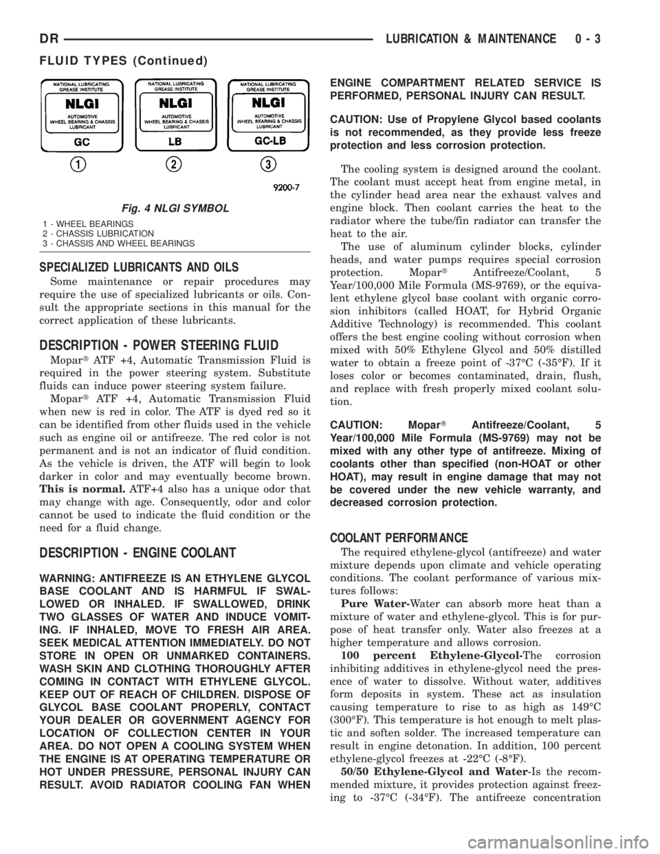
Fig. 4 NLGI SYMBOL
1 - WHEEL BEARINGS
2 - CHASSIS LUBRICATION
3 - CHASSIS AND WHEEL BEARINGS
DRLUBRICATION & MAINTENANCE 0 - 3
FLUID TYPES (Continued)
Page 18 of 2895
FLUID ADDITIVES
DaimlerChrysler strongly recommends against the
addition of any fluids to the transmission, other than
those automatic transmission fluids listed above.
Exceptions to this policy are the use of special dyes
to aid in detecting fluid leaks.
Various ªspecialº additives and supplements exist
that claim to improve shift feel and/or quality. These
additives and others also claim to improve converter
clutch operation and inhibit overheating, oxidation,
varnish, and sludge. These claims have not been sup-
ported to the satisfaction of DaimlerChrysler and
these additivesmust not be used.The use of trans-
mission ªsealersº should also be avoided, since they
may adversely affect the integrity of transmission
seals.
OPERATION - AUTOMATIC TRANSMISSION
FLUID
The automatic transmission fluid is selected based
upon several qualities. The fluid must provide a high
level of protection for the internal components by
providing a lubricating film between adjacent metal
components. The fluid must also be thermally stable
so that it can maintain a consistent viscosity through
a large temperature range. If the viscosity stays con-
stant through the temperature range of operation,
transmission operation and shift feel will remain con-
sistent. Transmission fluid must also be a good con-
ductor of heat. The fluid must absorb heat from the
internal transmission components and transfer that
heat to the transmission case.
FLUID CAPACITIES
SPECIFICATIONS
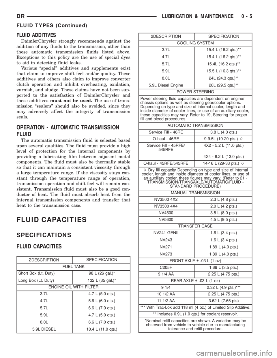
FLUID CAPACITIES
2DESCRIPTIONSPECIFICATION
FUEL TANK
Short Box (Lt. Duty) 98 L (26 gal.)*
Long Box (Lt. Duty) 132 L (35 gal.)*
ENGINE OIL WITH FILTER
3.7L 4.7 L (5.0 qts.)
4.7L 5.6 L (6.0 qts.)
5.7L 6.6 L (7.0 qts.)
5.9L 4.7 L (5.0 qts.)
8.0L 6.6 L (7.0 qts.)
5.9L DIESEL 10.4 L (11.0 qts.)
2DESCRIPTION SPECIFICATION
COOLING SYSTEM
3.7L 15.4 L (16.2 qts.)**
4.7L 15.4 L (16.2 qts.)**
5.7L 15.4L (16.2 qts.)**
5.9L 15.5 L (16.3 qts.)**
8.0L 24L (24.3 qts.)**
5.9L Diesel Engine 28L (29.5 qts.)**
POWER STEERING
Power steering fluid capacities are dependent on engine/
chassis options as well as steering gear/cooler options.
Depending on type and size of internal cooler, length and
inside diameter of cooler lines, or use of an auxiliary cooler,
these capacities may vary. Refer to 19, Steering for proper
fill and bleed procedures.
AUTOMATIC TRANSMISSION
Service Fill - 46RE 3.8 L (4.0 qts.)
O-haul - 46RE 9-9.5L (19-20 pts.)L
Service Fill - 45RFE/
545RFE4X2 - 5.2 L (11.0 pts.)
4X4 - 6.2 L (13.0 pts.)
O-haul - 45RFE/545RFE 14-16 L (29-33 pts.)L
LDry fill capacity Depending on type and size of internal
cooler, length and inside diameter of cooler lines, or use of
an auxiliary cooler, these figures may vary. (Refer to 21 -
TRANSMISSION/TRANSAXLE/AUTOMATIC/FLUID -
STANDARD PROCEDURE)
MANUAL TRANSMISSION
NV3500 4X2 2.3 L (4.8 pts.)
NV3500 4X4 2.0 L (4.2 pts.)
NV4500 3.8 L (8.0 pts.)
NV5600 4.5 L (9.5 pts.)
TRANSFER CASE
NV241 GENII 1.6 L (3.4 pts.)
NV243 1.6 L (3.4 pts.)
NV271 1.89 L (4.0 pts.)
NV273 1.89 L (4.0 pts.)
FRONT AXLE .03 L (1 oz)
C205F 1.66 L (3.5 pts.)
9 1/4 AA 2.25 L (4.75 pts.)
REAR AXLE .03 L (1 oz)
9 1/4 2.32 L (4.9 pts.)***
10 1/2 AA 2.25 L (4.75 pts.)
11 1/2 AA 3.62 L (7.65 pts)
*** With Trac-Lok add 118 ml (4 oz.) of Limited Slip Additive.
** Includes 0.9L (1.0 qts.) for coolant reservoir.
*Nominal refill capacities are shown. A variation may be
observed from vehicle to vehicle due to manufacturing
tolerance and refill procedure.
DRLUBRICATION & MAINTENANCE 0 - 5
FLUID TYPES (Continued)
Page 38 of 2895
FRONT - INDEPENDENT
FRONT SUSPENSION
DESCRIPTION
DESCRIPTION
The front suspension is designed to allow each
wheel to adapt to different road surfaces indepen-
dently. The wheels are mounted to hub/bearings
units bolted to the steering knuckle. The double-row
hub bearings are sealed and lubricated for life. The
steering knuckles turn (pivot) on ball joints.
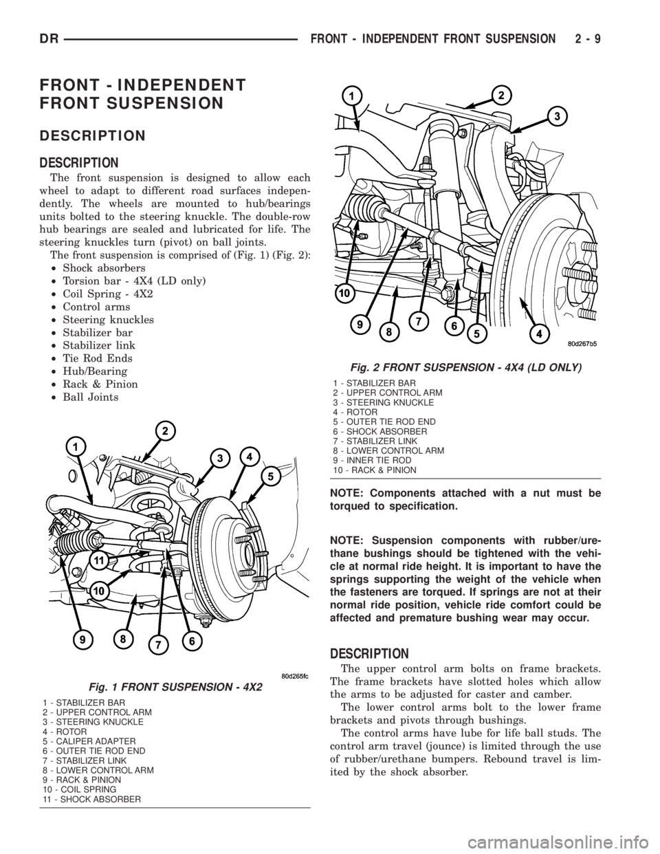
The front suspension is comprised of (Fig. 1) (Fig. 2):
²Shock absorbers
²Torsion bar - 4X4 (LD only)
²Coil Spring - 4X2
²Control arms
²Steering knuckles
²Stabilizer bar
²Stabilizer link
²Tie Rod Ends
²Hub/Bearing
²Rack & Pinion
²Ball Joints
NOTE: Components attached with a nut must be
torqued to specification.
NOTE: Suspension components with rubber/ure-
thane bushings should be tightened with the vehi-
cle at normal ride height. It is important to have the
springs supporting the weight of the vehicle when
the fasteners are torqued. If springs are not at their
normal ride position, vehicle ride comfort could be
affected and premature bushing wear may occur.
DESCRIPTION
The upper control arm bolts on frame brackets.
The frame brackets have slotted holes which allow
the arms to be adjusted for caster and camber.
The lower control arms bolt to the lower frame
brackets and pivots through bushings.
The control arms have lube for life ball studs. The
control arm travel (jounce) is limited through the use
of rubber/urethane bumpers. Rebound travel is lim-
ited by the shock absorber.
Fig. 1 FRONT SUSPENSION - 4X2
1 - STABILIZER BAR
2 - UPPER CONTROL ARM
3 - STEERING KNUCKLE
4 - ROTOR
5 - CALIPER ADAPTER
6 - OUTER TIE ROD END
7 - STABILIZER LINK
8 - LOWER CONTROL ARM
9 - RACK & PINION
10 - COIL SPRING
11 - SHOCK ABSORBER
Fig. 2 FRONT SUSPENSION - 4X4 (LD ONLY)
1 - STABILIZER BAR
2 - UPPER CONTROL ARM
3 - STEERING KNUCKLE
4 - ROTOR
5 - OUTER TIE ROD END
6 - SHOCK ABSORBER
7 - STABILIZER LINK
8 - LOWER CONTROL ARM
9 - INNER TIE ROD
10 - RACK & PINION
DRFRONT - INDEPENDENT FRONT SUSPENSION 2 - 9
Page 39 of 2895
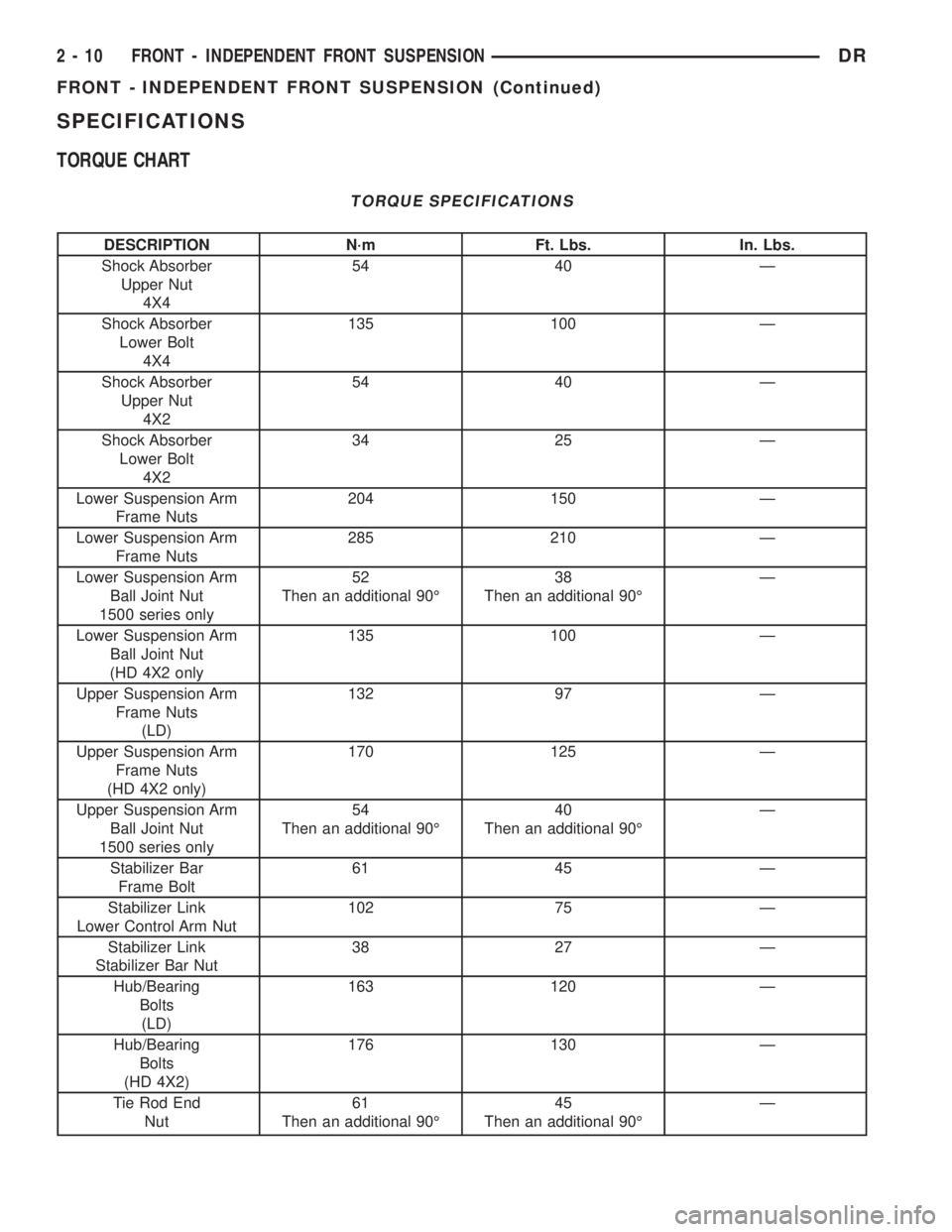
SPECIFICATIONS
TORQUE CHART
TORQUE SPECIFICATIONS
DESCRIPTION N´m Ft. Lbs. In. Lbs.
Shock Absorber
Upper Nut
4X454 40 Ð
Shock Absorber
Lower Bolt
4X4135 100 Ð
Shock Absorber
Upper Nut
4X254 40 Ð
Shock Absorber
Lower Bolt
4X234 25 Ð
Lower Suspension Arm
Frame Nuts204 150 Ð
Lower Suspension Arm
Frame Nuts285 210 Ð
Lower Suspension Arm
Ball Joint Nut
1500 series only52
Then an additional 90É38
Then an additional 90ÉÐ
Lower Suspension Arm
Ball Joint Nut
(HD 4X2 only135 100 Ð
Upper Suspension Arm
Frame Nuts
(LD)132 97 Ð
Upper Suspension Arm
Frame Nuts
(HD 4X2 only)170 125 Ð
Upper Suspension Arm
Ball Joint Nut
1500 series only54
Then an additional 90É40
Then an additional 90ÉÐ
Stabilizer Bar
Frame Bolt61 45 Ð
Stabilizer Link
Lower Control Arm Nut102 75 Ð
Stabilizer Link
Stabilizer Bar Nut38 27 Ð
Hub/Bearing
Bolts
(LD)163 120 Ð
Hub/Bearing
Bolts
(HD 4X2)176 130 Ð
Tie Rod End
Nut61
Then an additional 90É45
Then an additional 90ÉÐ
2 - 10 FRONT - INDEPENDENT FRONT SUSPENSIONDR
FRONT - INDEPENDENT FRONT SUSPENSION (Continued)
Page 44 of 2895
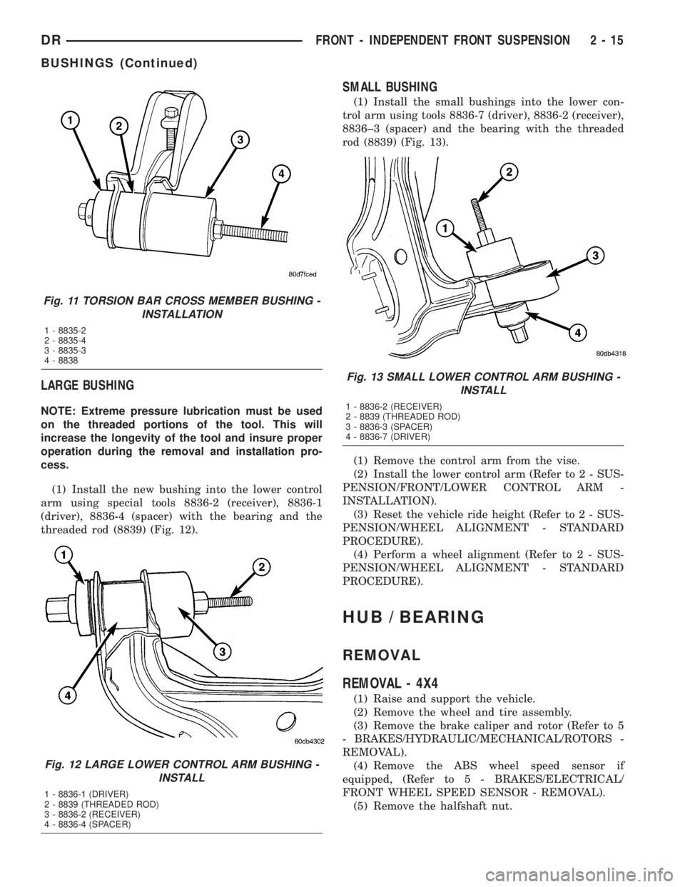
LARGE BUSHING
NOTE: Extreme pressure lubrication must be used
on the threaded portions of the tool. This will
increase the longevity of the tool and insure proper
operation during the removal and installation pro-
cess.
(1) Install the new bushing into the lower control
arm using special tools 8836-2 (receiver), 8836-1
(driver), 8836-4 (spacer) with the bearing and the
threaded rod (8839) (Fig. 12).
SMALL BUSHING
(1) Install the small bushings into the lower con-
trol arm using tools 8836-7 (driver), 8836-2 (receiver),
8836±3 (spacer) and the bearing with the threaded
rod (8839) (Fig. 13).
(1) Remove the control arm from the vise.
(2) Install the lower control arm (Refer to 2 - SUS-
PENSION/FRONT/LOWER CONTROL ARM -
INSTALLATION).
(3) Reset the vehicle ride height (Refer to 2 - SUS-
PENSION/WHEEL ALIGNMENT - STANDARD
PROCEDURE).
(4) Perform a wheel alignment (Refer to 2 - SUS-
PENSION/WHEEL ALIGNMENT - STANDARD
PROCEDURE).
HUB / BEARING
REMOVAL
REMOVAL - 4X4
(1) Raise and support the vehicle.
(2) Remove the wheel and tire assembly.
(3) Remove the brake caliper and rotor (Refer to 5
- BRAKES/HYDRAULIC/MECHANICAL/ROTORS -
REMOVAL).
(4) Remove the ABS wheel speed sensor if
equipped, (Refer to 5 - BRAKES/ELECTRICAL/
FRONT WHEEL SPEED SENSOR - REMOVAL).
(5) Remove the halfshaft nut.
Fig. 11 TORSION BAR CROSS MEMBER BUSHING -
INSTALLATION
1 - 8835-2
2 - 8835-4
3 - 8835-3
4 - 8838
Fig. 12 LARGE LOWER CONTROL ARM BUSHING -
INSTALL
1 - 8836-1 (DRIVER)
2 - 8839 (THREADED ROD)
3 - 8836-2 (RECEIVER)
4 - 8836-4 (SPACER)
Fig. 13 SMALL LOWER CONTROL ARM BUSHING -
INSTALL
1 - 8836-2 (RECEIVER)
2 - 8839 (THREADED ROD)
3 - 8836-3 (SPACER)
4 - 8836-7 (DRIVER)
DRFRONT - INDEPENDENT FRONT SUSPENSION 2 - 15
BUSHINGS (Continued)
Page 45 of 2895
NOTE: Do not strike the knuckle with a hammer to
remove the tie rod end or the ball joint. Damage to
the steering knuckle will occur.
(6) Remove the tie rod end nut and separate the
tie rod from the knuckle using special tool 8677.
(7) Remove the upper ball joint nut and separate
the upper ball joint from the knuckle using special
tool 8677.
(8) Pull down on the steering knuckle to separate
the halfshaft from the hub/bearing.
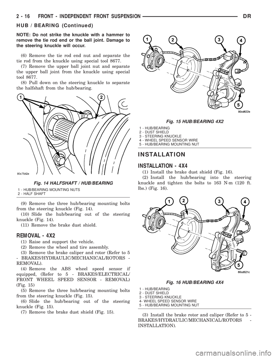
(9) Remove the three hub/bearing mounting bolts
from the steering knuckle (Fig. 14).
(10) Slide the hub/bearing out of the steering
knuckle (Fig. 14).
(11) Remove the brake dust shield.
REMOVAL - 4X2
(1) Raise and support the vehicle.
(2) Remove the wheel and tire assembly.
(3) Remove the brake caliper and rotor (Refer to 5
- BRAKES/HYDRAULIC/MECHANICAL/ROTORS -
REMOVAL).
(4) Remove the ABS wheel speed sensor if
equipped, (Refer to 5 - BRAKES/ELECTRICAL/
FRONT WHEEL SPEED SENSOR - REMOVAL)
(Fig. 15)
(5) Remove the three hub/bearing mounting bolts
from the steering knuckle (Fig. 15).
(6) Slide the hub/bearing out of the steering
knuckle (Fig. 15).
(7) Remove the brake dust shield (Fig. 15).
INSTALLATION
INSTALLATION - 4X4
(1) Install the brake dust shield (Fig. 16).
(2) Install the hub/bearing into the steering
knuckle and tighten the bolts to 163 N´m (120 ft.
lbs.) (Fig. 16).
(3) Install the brake rotor and caliper (Refer to 5 -
BRAKES/HYDRAULIC/MECHANICAL/ROTORS -
INSTALLATION).
Fig. 14 HALFSHAFT / HUB/BEARING
1 - HUB/BEARING MOUNTING NUTS
2 - HALF SHAFT
Fig. 15 HUB/BEARING 4X2
1 - HUB/BEARING
2 - DUST SHIELD
3 - STEERING KNUCKLE
4 - WHEEL SPEED SENSOR WIRE
5 - HUB/BEARING MOUNTING NUT
Fig. 16 HUB/BEARING 4X4
1 - HUB/BEARING
2 - DUST SHIELD
3 - STEERING KNUCKLE
4- WHEEL SPEED SENSOR WIRE
5 - HUB/BEARING MOUNTING NUT
2 - 16 FRONT - INDEPENDENT FRONT SUSPENSIONDR
HUB / BEARING (Continued)
Page 46 of 2895
(4) Install the ABS wheel speed sensor if equipped
(Refer to 5 - BRAKES/ELECTRICAL/FRONT
WHEEL SPEED SENSOR - INSTALLATION).
(5) Install the upper ball joint nut to the steering
knuckle and tighten to 54 N´m (40 ft. lbs.) (on 1500
series only an additional 90É turn).
(6) Install the tie rod end nut to the steering
knuckle and tighten to 61 N´m (45 ft. lbs.) then an
additional 90É.
(7) Install the halfshaft nut and tighten to 251
N´m (185 ft. lbs.).
(8) Install the wheel and tire assembly (Refer to 22
- TIRES/WHEELS/WHEELS - STANDARD PROCE-
DURE).
(9) Remove the support and lower vehicle.
INSTALLATION - 4X2
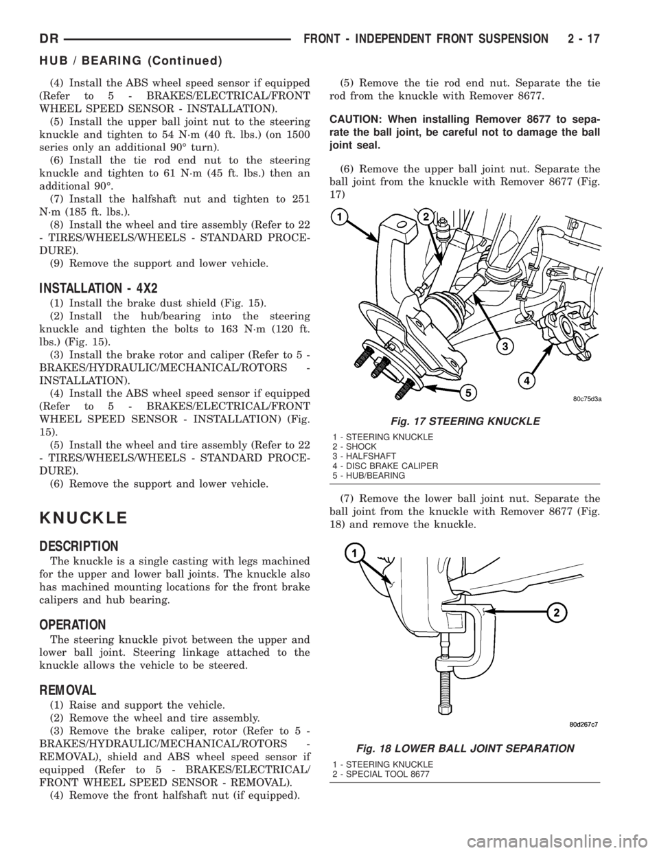
(1) Install the brake dust shield (Fig. 15).
(2) Install the hub/bearing into the steering
knuckle and tighten the bolts to 163 N´m (120 ft.
lbs.) (Fig. 15).
(3) Install the brake rotor and caliper (Refer to 5 -
BRAKES/HYDRAULIC/MECHANICAL/ROTORS -
INSTALLATION).
(4) Install the ABS wheel speed sensor if equipped
(Refer to 5 - BRAKES/ELECTRICAL/FRONT
WHEEL SPEED SENSOR - INSTALLATION) (Fig.
15).
(5) Install the wheel and tire assembly (Refer to 22
- TIRES/WHEELS/WHEELS - STANDARD PROCE-
DURE).
(6) Remove the support and lower vehicle.
KNUCKLE
DESCRIPTION
The knuckle is a single casting with legs machined
for the upper and lower ball joints. The knuckle also
has machined mounting locations for the front brake
calipers and hub bearing.
OPERATION
The steering knuckle pivot between the upper and
lower ball joint. Steering linkage attached to the
knuckle allows the vehicle to be steered.
REMOVAL
(1) Raise and support the vehicle.
(2) Remove the wheel and tire assembly.
(3) Remove the brake caliper, rotor (Refer to 5 -
BRAKES/HYDRAULIC/MECHANICAL/ROTORS -
REMOVAL), shield and ABS wheel speed sensor if
equipped (Refer to 5 - BRAKES/ELECTRICAL/
FRONT WHEEL SPEED SENSOR - REMOVAL).
(4) Remove the front halfshaft nut (if equipped).(5) Remove the tie rod end nut. Separate the tie
rod from the knuckle with Remover 8677.
CAUTION: When installing Remover 8677 to sepa-
rate the ball joint, be careful not to damage the ball
joint seal.
(6) Remove the upper ball joint nut. Separate the
ball joint from the knuckle with Remover 8677 (Fig.
17)
(7) Remove the lower ball joint nut. Separate the
ball joint from the knuckle with Remover 8677 (Fig.
18) and remove the knuckle.
Fig. 17 STEERING KNUCKLE
1 - STEERING KNUCKLE
2 - SHOCK
3 - HALFSHAFT
4 - DISC BRAKE CALIPER
5 - HUB/BEARING
Fig. 18 LOWER BALL JOINT SEPARATION
1 - STEERING KNUCKLE
2 - SPECIAL TOOL 8677
DRFRONT - INDEPENDENT FRONT SUSPENSION 2 - 17
HUB / BEARING (Continued)
Page 47 of 2895
(8) Remove the hub/bearing from the steering
knuckle (Refer to 2 - SUSPENSION/FRONT/HUB /
BEARING - REMOVAL).
INSTALLATION
CAUTION: The ball joint stud tapers must be
CLEAN and DRY before installing the knuckle.
Clean the stud tapers with mineral spirits to remove
dirt and grease.
NOTE: When installing hub/bearing with ABS
brakes, position the speed sensor opening towards
the front of the vehicle.
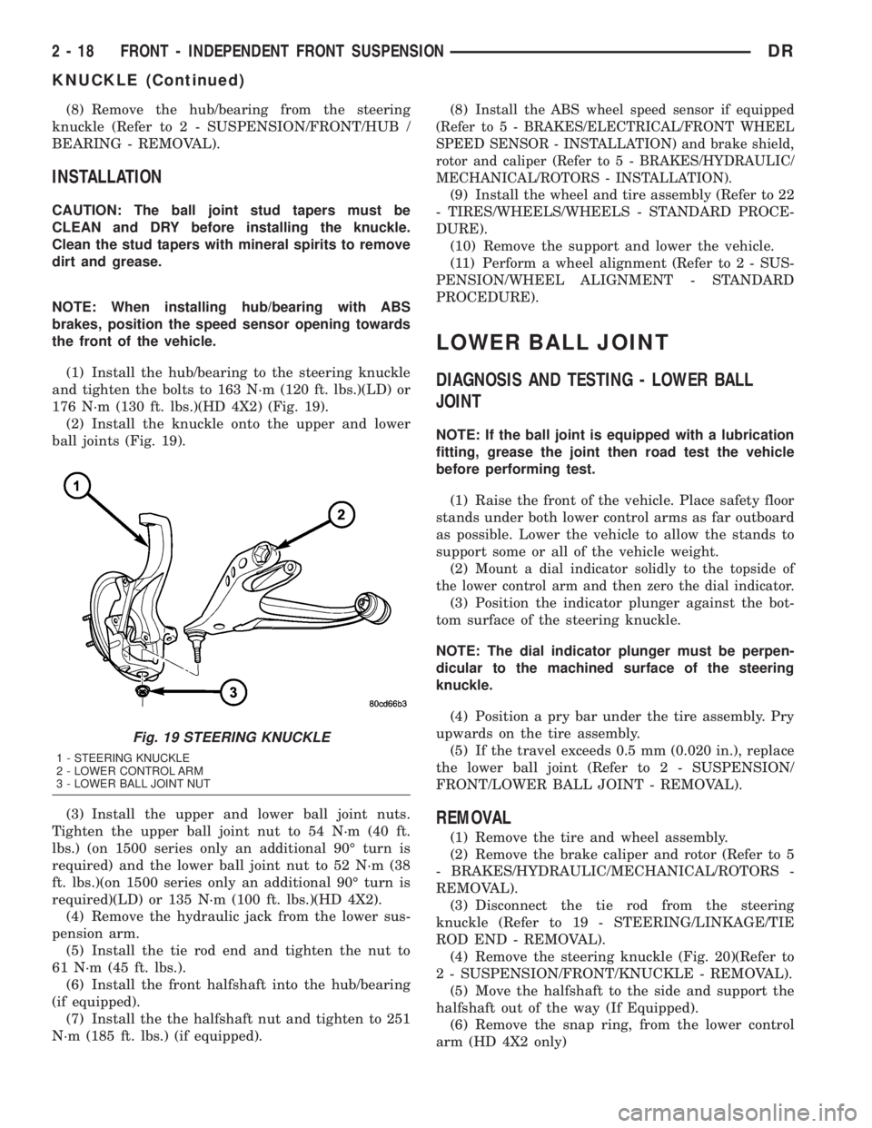
(1) Install the hub/bearing to the steering knuckle
and tighten the bolts to 163 N´m (120 ft. lbs.)(LD) or
176 N´m (130 ft. lbs.)(HD 4X2) (Fig. 19).
(2) Install the knuckle onto the upper and lower
ball joints (Fig. 19).
(3) Install the upper and lower ball joint nuts.
Tighten the upper ball joint nut to 54 N´m (40 ft.
lbs.) (on 1500 series only an additional 90É turn is
required) and the lower ball joint nut to 52 N´m (38
ft. lbs.)(on 1500 series only an additional 90É turn is
required)(LD) or 135 N´m (100 ft. lbs.)(HD 4X2).
(4) Remove the hydraulic jack from the lower sus-
pension arm.
(5) Install the tie rod end and tighten the nut to
61 N´m (45 ft. lbs.).
(6) Install the front halfshaft into the hub/bearing
(if equipped).
(7) Install the the halfshaft nut and tighten to 251
N´m (185 ft. lbs.) (if equipped).(8)
Install the ABS wheel speed sensor if equipped
(Refer to 5 - BRAKES/ELECTRICAL/FRONT WHEEL
SPEED SENSOR - INSTALLATION) and brake shield,
rotor and caliper (Refer to 5 - BRAKES/HYDRAULIC/
MECHANICAL/ROTORS - INSTALLATION).
(9) Install the wheel and tire assembly (Refer to 22
- TIRES/WHEELS/WHEELS - STANDARD PROCE-
DURE).
(10) Remove the support and lower the vehicle.
(11) Perform a wheel alignment (Refer to 2 - SUS-
PENSION/WHEEL ALIGNMENT - STANDARD
PROCEDURE).
LOWER BALL JOINT
DIAGNOSIS AND TESTING - LOWER BALL
JOINT
NOTE: If the ball joint is equipped with a lubrication
fitting, grease the joint then road test the vehicle
before performing test.
(1) Raise the front of the vehicle. Place safety floor
stands under both lower control arms as far outboard
as possible. Lower the vehicle to allow the stands to
support some or all of the vehicle weight.
(2)
Mount a dial indicator solidly to the topside of
the lower control arm and then zero the dial indicator.
(3) Position the indicator plunger against the bot-
tom surface of the steering knuckle.
NOTE: The dial indicator plunger must be perpen-
dicular to the machined surface of the steering
knuckle.
(4) Position a pry bar under the tire assembly. Pry
upwards on the tire assembly.
(5) If the travel exceeds 0.5 mm (0.020 in.), replace
the lower ball joint (Refer to 2 - SUSPENSION/
FRONT/LOWER BALL JOINT - REMOVAL).
REMOVAL
(1) Remove the tire and wheel assembly.
(2) Remove the brake caliper and rotor (Refer to 5
- BRAKES/HYDRAULIC/MECHANICAL/ROTORS -
REMOVAL).
(3) Disconnect the tie rod from the steering
knuckle (Refer to 19 - STEERING/LINKAGE/TIE
ROD END - REMOVAL).
(4) Remove the steering knuckle (Fig. 20)(Refer to
2 - SUSPENSION/FRONT/KNUCKLE - REMOVAL).
(5) Move the halfshaft to the side and support the
halfshaft out of the way (If Equipped).
(6) Remove the snap ring, from the lower control
arm (HD 4X2 only)
Fig. 19 STEERING KNUCKLE
1 - STEERING KNUCKLE
2 - LOWER CONTROL ARM
3 - LOWER BALL JOINT NUT
2 - 18 FRONT - INDEPENDENT FRONT SUSPENSIONDR
KNUCKLE (Continued)
Page 49 of 2895
LOWER CONTROL ARM
REMOVAL
REMOVAL - 4X4 (LD)
(1) Raise and support the vehicle.
(2) Remove the wheel and tire assembly.
(3) Remove the upper ball joint nut. Separate ball
joint from the steering knuckle with Remover 8677.
(4) Remove the front halfshaft, (Refer to 3 - DIF-
FERENTIAL & DRIVELINE/HALF SHAFT -
REMOVAL).
(5) Remove the torsion bar, (Refer to 2 - SUSPEN-
SION/FRONT/TRACK BAR - REMOVAL).
(6) Remove the shock absorber lower bolt.
(7) Remove the stabilizer bar link (Refer to 2 -
SUSPENSION/FRONT/STABILIZER LINK -
REMOVAL).
(8) Remove the lower ball joint nut. Separate ball
joint from the steering knuckle with Remover 8677.
(9) Remove the control arm pivot bolts and suspen-
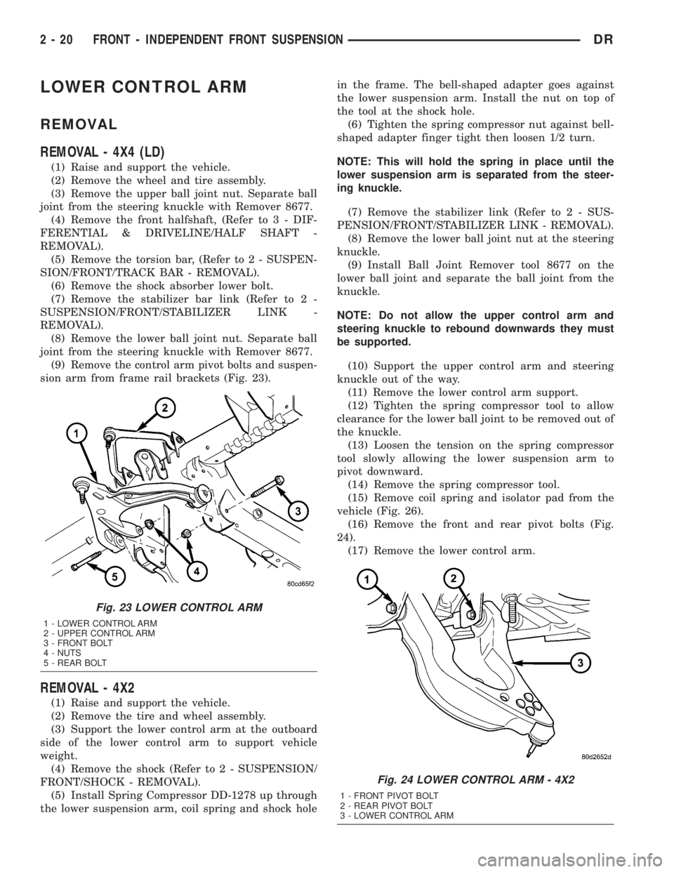
sion arm from frame rail brackets (Fig. 23).
REMOVAL - 4X2
(1) Raise and support the vehicle.
(2) Remove the tire and wheel assembly.
(3) Support the lower control arm at the outboard
side of the lower control arm to support vehicle
weight.
(4) Remove the shock (Refer to 2 - SUSPENSION/
FRONT/SHOCK - REMOVAL).
(5) Install Spring Compressor DD-1278 up through
the lower suspension arm, coil spring and shock holein the frame. The bell-shaped adapter goes against
the lower suspension arm. Install the nut on top of
the tool at the shock hole.
(6) Tighten the spring compressor nut against bell-
shaped adapter finger tight then loosen 1/2 turn.
NOTE: This will hold the spring in place until the
lower suspension arm is separated from the steer-
ing knuckle.
(7) Remove the stabilizer link (Refer to 2 - SUS-
PENSION/FRONT/STABILIZER LINK - REMOVAL).
(8) Remove the lower ball joint nut at the steering
knuckle.
(9) Install Ball Joint Remover tool 8677 on the
lower ball joint and separate the ball joint from the
knuckle.
NOTE: Do not allow the upper control arm and
steering knuckle to rebound downwards they must
be supported.
(10) Support the upper control arm and steering
knuckle out of the way.
(11) Remove the lower control arm support.
(12) Tighten the spring compressor tool to allow
clearance for the lower ball joint to be removed out of
the knuckle.
(13) Loosen the tension on the spring compressor
tool slowly allowing the lower suspension arm to
pivot downward.
(14) Remove the spring compressor tool.
(15) Remove coil spring and isolator pad from the
vehicle (Fig. 26).
(16) Remove the front and rear pivot bolts (Fig.
24).
(17) Remove the lower control arm.
Fig. 23 LOWER CONTROL ARM
1 - LOWER CONTROL ARM
2 - UPPER CONTROL ARM
3 - FRONT BOLT
4 - NUTS
5 - REAR BOLT
Fig. 24 LOWER CONTROL ARM - 4X2
1 - FRONT PIVOT BOLT
2 - REAR PIVOT BOLT
3 - LOWER CONTROL ARM
2 - 20 FRONT - INDEPENDENT FRONT SUSPENSIONDR
Page 50 of 2895
INSTALLATION
INSTALLATION - 4X4 (LD)
(1) Position the lower control arm at the frame rail
brackets. Install the pivot bolts and nuts. Tighten the
nuts finger-tight.
CAUTION: The ball joint stud taper must be CLEAN
and DRY before installing the knuckle. Clean the
stud taper with mineral spirits to remove dirt and
grease.
(2) Insert the lower ball joint into the steering
knuckle. Install and tighten the retaining nut to 52
N´m (38 ft. lbs.)(on 1500 series only an additional 90É
turn is required).
(3) Install the torsion bar, (Refer to 2 - SUSPEN-
SION/FRONT/TRACK BAR - INSTALLATION).
(4) Install shock absorber lower bolt and tighten to
135 N´m (100 ft. lbs.).
(5) Install the front halfshaft, (Refer to 3 - DIF-
FERENTIAL & DRIVELINE/HALF SHAFT -
INSTALLATION).
(6) Insert the upper ball joint into the steering
knuckle. Install and tighten the retaining nut to 54
N´m (40 ft. lbs.)(on 1500 series only an additional 90É
turn is required).
(7) Install the stabilizer bar link (Refer to 2 - SUS-
PENSION/FRONT/STABILIZER LINK - INSTALLA-
TION).
(8) Tighten the lower control arm front pivot nut
to 204 N´m (150 ft. lbs.). Tighten rear pivot bolt to
204 N´m (150 ft. lbs.).
(9) Install the wheel and tire assembly,(Refer to 22
- TIRES/WHEELS/WHEELS - STANDARD PROCE-
DURE).
(10) Remove the support and lower the vehicle.
(11) Adjust the front suspension height and per-
form a wheel alignment (Refer to 2 - SUSPENSION/
WHEEL ALIGNMENT - STANDARD PROCEDURE).
INSTALLATION - 4X2
(1) Install the lower control arm into place on the
vehicle.
(2) Install the front and rear control arm pivot
bolts finger tight.
(3) Install the coil spring into the frame pocket(Re-
fer to 2 - SUSPENSION/FRONT/SPRING - INSTAL-
LATION).
(4) Install the Spring Compressor DD-1278 up
through the lower suspension arm, coil spring and
shock hole in the frame.
(5) Tighten the tool nut to compress the coil
spring.
(6) Remove the support from the upper control
arm and steering knuckle.(7) Position the lower ball joint into the steering
knuckle.
(8) Install the retaining nut on the lower ball joint
and tighten to 52 N´m (38 ft. lbs.)(on 1500 series only
an additional 90É turn is required) or 135 N´m (100
ft. lbs.)(HD 4X2 only).
(9) Support the lower control arm at the outboard
side of the lower control arm to support vehicle
weight.
(10) Remove the spring compressor tool.
(11) Install the shock absorber. (Refer to 2 - SUS-
PENSION/FRONT/SHOCK - INSTALLATION).
(12) Install the stabilizer link (Refer to 2 - SUS-
PENSION/FRONT/STABILIZER LINK - INSTALLA-
TION).
(13) Remove the lower control arm support.
(14) Install the wheel and tire assembly and lower
the vehicle. (Refer to 22 - TIRES/WHEELS/WHEELS
- STANDARD PROCEDURE).
(15) Lower the vehicle to the floor with vehicle
weight and Tighten the front and rear control arm
pivot bolts to 204 N´m (150 ft. lbs.)(LD) or 285 N´m
(210 ft. lbs.)(HD 4X2 only).
(16) Perform a wheel alignment (Refer to 2 - SUS-
PENSION/WHEEL ALIGNMENT - STANDARD
PROCEDURE).
SPRING
REMOVAL
(1) Raise and support vehicle.
(2) Remove the front wheel and tire assembly.
(3)
Support the lower control arm at the outboard
side of the lower control arm to support vehicle weight.
(4) Remove the shock absorber (Refer to 2 - SUS-
PENSION/FRONT/SHOCK - REMOVAL).
(5) Install Spring Compressor DD-1278 up through
the lower suspension arm, coil spring and shock hole
in the frame. The bell-shaped adapter goes against
the lower suspension arm. Install the nut on top of
the tool at the shock hole (Fig. 25).
(6) Tighten the spring compressor nut against bell-
shaped adapter finger tight then loosen 1/2 turn.
NOTE: This will hold the spring in place until the
lower suspension arm is separated from the steer-
ing knuckle.
(7) Remove the stabilizer link (Refer to 2 - SUS-
PENSION/FRONT/STABILIZER LINK - REMOVAL).
(8) Remove the lower ball joint nut at the steering
knuckle.
(9) Install Ball Joint Remover tool 8677 on the
lower ball joint and separate the ball joint from the
knuckle.
(10)
DRFRONT - INDEPENDENT FRONT SUSPENSION 2 - 21
LOWER CONTROL ARM (Continued)