Engine wire harness DODGE RAM 2003 Service Repair Manual
[x] Cancel search | Manufacturer: DODGE, Model Year: 2003, Model line: RAM, Model: DODGE RAM 2003Pages: 2895, PDF Size: 83.15 MB
Page 321 of 2895
NOTE: The engine speed sensor face is very close
to the accessory drive belt. Inspect engine speed
sensor and wire harness for damage when acces-
sory drive belt has been replaced due to failure or
abnormal conditions.
REMOVAL
CAUTION: Do not attempt to check belt tension with
a belt tension gauge on vehicles equipped with an
automatic belt tensioner. Refer to Automatic Belt
Tensioner in this group.
NOTE: The belt routing schematics are published
from the latest information available at the time of
publication. If anything differs between these sche-
matics and the Belt Routing Label, use the sche-
matics on Belt Routing Label.This label is located in
the engine compartment.
Drive belts on diesel engines are equipped with a
spring loaded automatic belt tensioner.displays the
tensioner for vehicles without air conditioning.
This belt tensioner will be used on all belt config-
urations, such as with or without air conditioning.
For more information, (Refer to 7 - COOLING/AC-
CESSORY DRIVE/BELT TENSIONERS - DESCRIP-
TION).
(1) A 1/2 inch square hole is provided in the auto-
matic belt tensioner. Attach a 1/2 inch drive-long
handle ratchet to this hole.
(2) Rotate ratchet and tensioner assembly clock-
wise (as viewed from front) until tension has been
relieved from belt.
(3) Remove belt from water pump pulley first.
(4) Remove belt from vehicle.
INSTALLATION
CAUTION: When installing the accessory drive belt,
the belt must be routed correctly. If not, engine mayoverheat due to water pump rotating in wrong
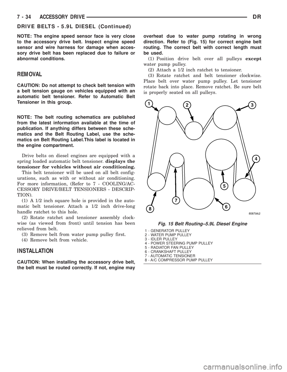
direction. Refer to (Fig. 15) for correct engine belt
routing. The correct belt with correct length must
be used.
(1) Position drive belt over all pulleysexcept
water pump pulley.
(2) Attach a 1/2 inch ratchet to tensioner.
(3) Rotate ratchet and belt tensioner clockwise.
Place belt over water pump pulley. Let tensioner
rotate back into place. Remove ratchet. Be sure belt
is properly seated on all pulleys.
Fig. 15 Belt Routing±5.9L Diesel Engine
1 - GENERATOR PULLEY
2 - WATER PUMP PULLEY
3 - IDLER PULLEY
4 - POWER STEERING PUMP PULLEY
5 - RADIATOR FAN PULLEY
6 - CRANKSHAFT PULLEY
7 - AUTOMATIC TENSIONER
8 - A/C COMPRESSOR PUMP PULLEY
7 - 34 ACCESSORY DRIVEDR
DRIVE BELTS - 5.9L DIESEL (Continued)
Page 371 of 2895
INSTALLATION
(1) Install antenna cable to radio.
(2) Connect electrical harness connector to radio.
(3) Install radio to instrument panel.
(4) Install instrument panel center bezel (Refer to
23 - BODY/INSTRUMENT PANEL/INSTRUMENT
PANEL CENTER BEZEL - INSTALLATION).
(5) Connect battery negative cable.
RADIO NOISE SUPPRESSION
GROUND STRAP
DESCRIPTION
Radio noise suppression devices are factory-in-
stalled standard equipment on this vehicle. Radio
Frequency Interference (RFI) and ElectroMagnetic
Interference (EMI) can be produced by any on-board
or external source of electromagnetic energy. These
electromagnetic energy sources can radiate electro-
magnetic signals through the air, or conduct them
through the vehicle electrical system.
When the audio system converts RFI or EMI to an
audible acoustic wave form, it is referred to as radio
noise. This undesirable radio noise is generally man-
ifested in the form of ªbuzzing,º ªhissing,º ªpopping,º
ªclicking,º ªcrackling,º and/or ªwhirringº sounds. In
most cases, RFI and EMI radio noise can be sup-
pressed using a combination of vehicle and compo-
nent grounding, filtering and shielding techniques.
This vehicle is equipped with factory-installed radio
noise suppression devices that were designed to min-
imize exposure to typical sources of RFI and EMI;
thereby, minimizing radio noise complaints.Factory-installed radio noise suppression is accom-
plished primarily through circuitry or devices that
are integral to the factory-installed radios, audio
power amplifiers and other on-board electrical com-
ponents such as generators, wiper motors, blower
motors, and fuel pumps that have been found to be
potential sources of RFI or EMI. External radio noise
suppression devices that are used on this vehicle to
control RFI or EMI, and can be serviced, include the
following:
²Engine-to-body ground strap- This length of
braided ground strap has an eyelet terminal connec-
tor crimped to each end. One end is secured to the
engine cylinder head(s). The other is secured to the
plenum at the exhaust heat shield forward/outer
attaching stud.
²Resistor-type spark plugs- This type of spark
plug has an internal resistor connected in series
between the spark plug terminal and the center elec-
trode to help reduce the production of electromag-
netic radiation that can result in radio noise.
OPERATION
There are two common strategies that can be used
to suppress Radio Frequency Interference (RFI) and
ElectroMagnetic Interference (EMI) radio noise. The
first suppression strategy involves preventing the
production of RFI and EMI electromagnetic signals
at their sources. The second suppression strategy
involves preventing the reception of RFI and EMI
electromagnetic signals by the audio system compo-
nents.
The use of braided ground straps in key locations
is part of the RFI and EMI prevention strategy.
These ground straps ensure adequate ground paths,
particularly for high current components such as
many of those found in the starting, charging, igni-
tion, engine control and transmission control sys-
tems. An insufficient ground path for any of these
high current components may result in radio noise
caused by induced voltages created as the high cur-
rent seeks alternative ground paths through compo-
nents or circuits intended for use by, or in close
proximity to the audio system components or circuits.
Preventing the reception of RFI and EMI is accom-
plished by ensuring that the audio system compo-
nents are correctly installed in the vehicle. Loose,
corroded or improperly soldered wire harness connec-
tions, improperly routed wiring and inadequate audio
system component grounding can all contribute to
the reception of RFI and EMI. A properly grounded
antenna body and radio chassis, as well as a shielded
antenna coaxial cable with clean and tight connec-
tions will each help reduce the potential for reception
of RFI and EMI.
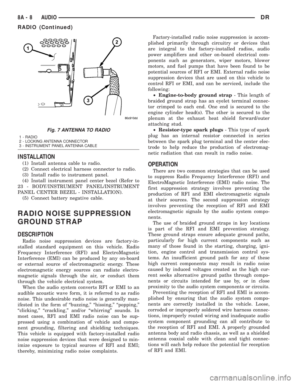
Fig. 7 ANTENNA TO RADIO
1 - RADIO
2 - LOCKING ANTENNA CONNECTOR
3 - INSTRUMENT PANEL ANTENNA CABLE
8A - 8 AUDIODR
RADIO (Continued)
Page 387 of 2895
DIAGNOSIS AND TESTING - FRONT CONTROL
MODULE
The front control module is a printed circuit board
based module with a on-board micro-processor. The
front control module interfaces with other electronic
modules in the vehicle via the Programmable Com-
munications Interface (PCI) data bus (J1850). In
order to obtain conclusive testing the Programmable
Communications Interface (PCI) data bus network
and all of the electronic modules that provide inputs
to, or receive outputs from the front control module
must be checked. All PCI (J1850) communication
faults must be resolved prior to further diagnosing
any front control module related issues.
The front control module was designed to be diag-
nosed with an appropriate diagnostic scan tool, such
as the DRB IIIt. The most reliable, efficient, and
accurate means to diagnose the front control module
requires the use of a DRB IIItscan tool and the
proper Body Diagnostic Procedures manual.
Before any testing of the front control module is
attempted, the battery should be fully charged and
all wire harness and ground connections inspected
around the affected areas on the vehicle.
REMOVAL
(1) Disconnect the positive and negative battery
cables from the battery.
(2) Partially remove the integrated power module
from the engine compartment (Refer to 8 - ELECTRI-
CAL/POWER DISTRIBUTION/INTEGRATED
POWER MODULE - REMOVAL).
(3) Remove the front control module retaining
screws.
(4) Using both hands, pull the front control module
straightfrom the integrated power module assembly
to disconnect the 49-way electrical connector and
remove the front control module from the vehicle.
INSTALLATION
(1) Install the front control module on the inte-
grated power module assembly by pushing the
49-way electrical connector straight in.
(2) Install the front control module retaining
screws. Torque the screws to 7 in. lbs.
(3) Install the integrated power module (Refer to 8
- ELECTRICAL/POWER DISTRIBUTION/INTE-
GRATED POWER MODULE - INSTALLATION).
(4) Connect the positive and negative battery
cables.
HEATED SEAT MODULE
DESCRIPTION
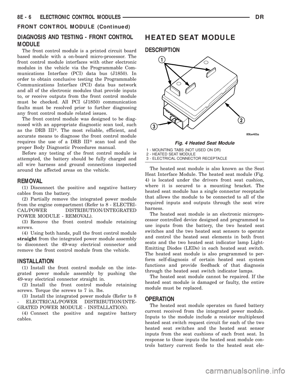
The heated seat module is also known as the Seat
Heat Interface Module. The heated seat module (Fig.
4) is located under the drivers front seat cushion,
where it is secured to a mounting bracket. The
heated seat module has a single connector receptacle
that allows the module to be connected to all of the
required inputs and outputs through the seat wire
harness.
The heated seat module is an electronic micropro-
cessor controlled device designed and programmed to
use inputs from the battery, the two heated seat
switches and the two heated seat sensors to operate
and control the heated seat elements in both front
seats and the two heated seat indicator lamp Light-
Emitting Diodes (LEDs) in each heated seat switch.
The heated seat module is also programmed to per-
form self-diagnosis of certain heated seat system
functions and provide feedback of that diagnosis
through the heated seat switch indicator lamps.
The heated seat module cannot be repaired. If the
heated seat module is damaged or faulty, the entire
module must be replaced.
OPERATION
The heated seat module operates on fused battery
current received from the integrated power module.
Inputs to the module include a resistor multiplexed
heated seat switch request circuit for each of the two
heated seat switches and the heated seat sensor
inputs from the seat cushions of each front seat. In
response to those inputs the heated seat module con-
trols battery current feeds to the heated seat ele-
Fig. 4 Heated Seat Module
1 - MOUNTING TABS (NOT USED ON DR)
2 - HEATED SEAT MODULE
3 - ELECTRICAL CONNECTOR RECEPTACLE
8E - 6 ELECTRONIC CONTROL MODULESDR
FRONT CONTROL MODULE (Continued)
Page 396 of 2895
NOTE: A maximum of eight keys can be learned to
each SKIM. Once a key is learned to a SKIM, it (the
key) cannot be transferred to another vehicle.
(5) If ignition key programming is unsuccessful,
the DRBIIItscan tool will display one of the follow-
ing messages:
(a) Programming Not Attempted - The DRBIIIt
scan tool attempts to read the programmed key
status and there are no keys programmed into
SKIM memory.
(b) Programming Key Failed (Possible Used Key
From Wrong Vehicle) - SKIM is unable to program
key due to one of the following:
²Faulty ignition key transponder.
²Ignition key is programmed to another vehicle.
(c) 8 Keys Already Learned, Programming Not
Done - SKIM transponder ID memory is full.
(6) Obtain ignition keys to be programmed from
customer (8 keys maximum).
(7) Using the DRBIIItscan tool, erase all ignition
keys by selecting MISCELLANEOUS and ERASE
ALL CURRENT IGN. KEYS.
(8) Program all ignition keys.
Learned Key In Ignition - Ignition key transponder
ID is currently programmed in SKIM memory.
REMOVAL
(1) Disconnect and isolate the battery negative
cable.
(2) Remove the steering column upper and lower
shrouds. Refer to Steering, Column, Shroud,
Removal.
(3) Disconnect the steering column wire harness
connector from the Sentry Key Immobilizer Module
(SKIM)
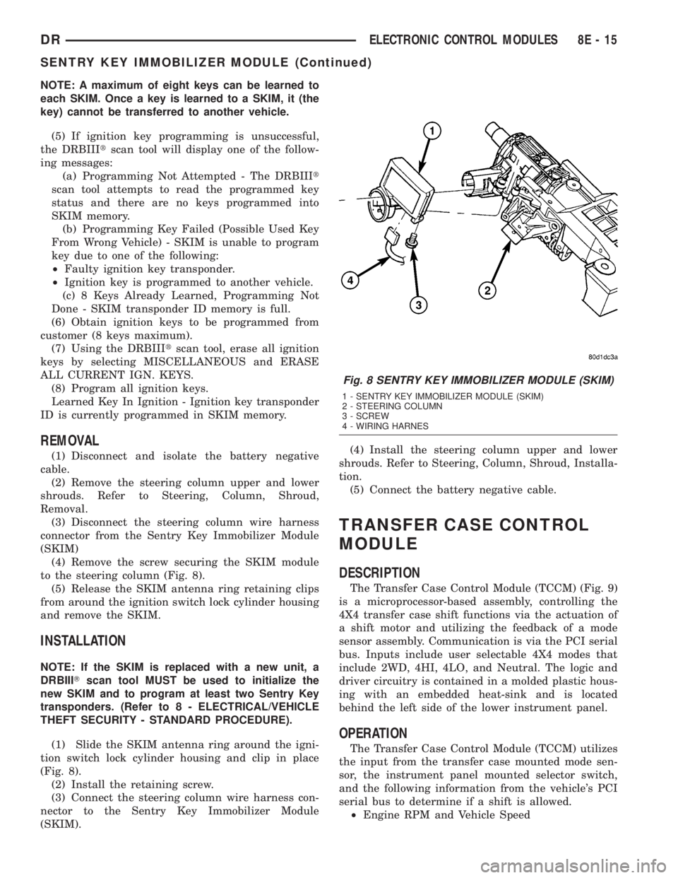
(4) Remove the screw securing the SKIM module
to the steering column (Fig. 8).
(5) Release the SKIM antenna ring retaining clips
from around the ignition switch lock cylinder housing
and remove the SKIM.
INSTALLATION
NOTE: If the SKIM is replaced with a new unit, a
DRBIIITscan tool MUST be used to initialize the
new SKIM and to program at least two Sentry Key
transponders. (Refer to 8 - ELECTRICAL/VEHICLE
THEFT SECURITY - STANDARD PROCEDURE).
(1) Slide the SKIM antenna ring around the igni-
tion switch lock cylinder housing and clip in place
(Fig. 8).
(2) Install the retaining screw.
(3) Connect the steering column wire harness con-
nector to the Sentry Key Immobilizer Module
(SKIM).(4) Install the steering column upper and lower
shrouds. Refer to Steering, Column, Shroud, Installa-
tion.
(5) Connect the battery negative cable.
TRANSFER CASE CONTROL
MODULE
DESCRIPTION
The Transfer Case Control Module (TCCM) (Fig. 9)
is a microprocessor-based assembly, controlling the
4X4 transfer case shift functions via the actuation of
a shift motor and utilizing the feedback of a mode
sensor assembly. Communication is via the PCI serial
bus. Inputs include user selectable 4X4 modes that
include 2WD, 4HI, 4LO, and Neutral. The logic and
driver circuitry is contained in a molded plastic hous-
ing with an embedded heat-sink and is located
behind the left side of the lower instrument panel.
OPERATION
The Transfer Case Control Module (TCCM) utilizes
the input from the transfer case mounted mode sen-
sor, the instrument panel mounted selector switch,
and the following information from the vehicle's PCI
serial bus to determine if a shift is allowed.
²Engine RPM and Vehicle Speed
Fig. 8 SENTRY KEY IMMOBILIZER MODULE (SKIM)
1 - SENTRY KEY IMMOBILIZER MODULE (SKIM)
2 - STEERING COLUMN
3 - SCREW
4 - WIRING HARNES
DRELECTRONIC CONTROL MODULES 8E - 15
SENTRY KEY IMMOBILIZER MODULE (Continued)
Page 420 of 2895
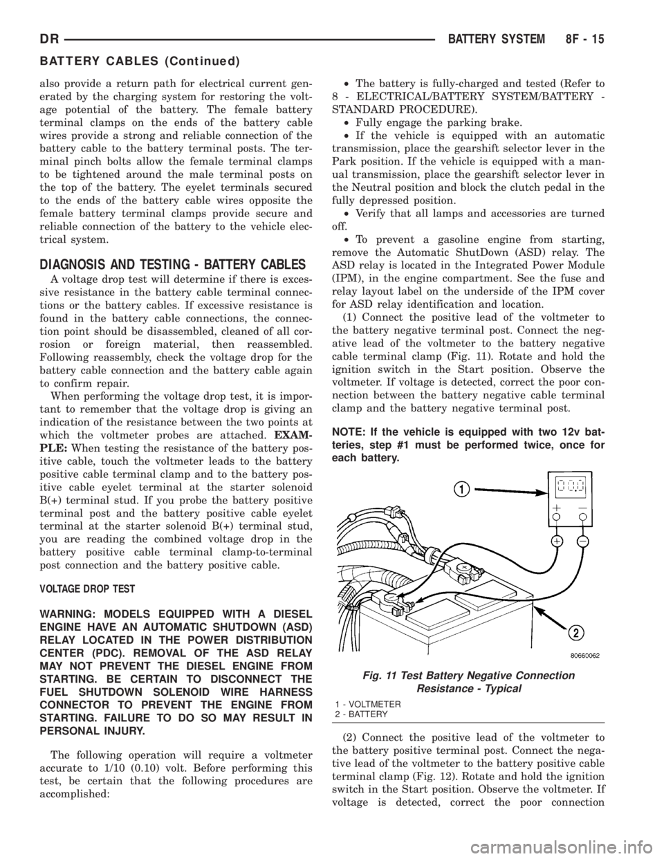
also provide a return path for electrical current gen-
erated by the charging system for restoring the volt-
age potential of the battery. The female battery
terminal clamps on the ends of the battery cable
wires provide a strong and reliable connection of the
battery cable to the battery terminal posts. The ter-
minal pinch bolts allow the female terminal clamps
to be tightened around the male terminal posts on
the top of the battery. The eyelet terminals secured
to the ends of the battery cable wires opposite the
female battery terminal clamps provide secure and
reliable connection of the battery to the vehicle elec-
trical system.
DIAGNOSIS AND TESTING - BATTERY CABLES
A voltage drop test will determine if there is exces-
sive resistance in the battery cable terminal connec-
tions or the battery cables. If excessive resistance is
found in the battery cable connections, the connec-
tion point should be disassembled, cleaned of all cor-
rosion or foreign material, then reassembled.
Following reassembly, check the voltage drop for the
battery cable connection and the battery cable again
to confirm repair.
When performing the voltage drop test, it is impor-
tant to remember that the voltage drop is giving an
indication of the resistance between the two points at
which the voltmeter probes are attached.EXAM-
PLE:When testing the resistance of the battery pos-
itive cable, touch the voltmeter leads to the battery
positive cable terminal clamp and to the battery pos-
itive cable eyelet terminal at the starter solenoid
B(+) terminal stud. If you probe the battery positive
terminal post and the battery positive cable eyelet
terminal at the starter solenoid B(+) terminal stud,
you are reading the combined voltage drop in the
battery positive cable terminal clamp-to-terminal
post connection and the battery positive cable.
VOLTAGE DROP TEST
WARNING: MODELS EQUIPPED WITH A DIESEL
ENGINE HAVE AN AUTOMATIC SHUTDOWN (ASD)
RELAY LOCATED IN THE POWER DISTRIBUTION
CENTER (PDC). REMOVAL OF THE ASD RELAY
MAY NOT PREVENT THE DIESEL ENGINE FROM
STARTING. BE CERTAIN TO DISCONNECT THE
FUEL SHUTDOWN SOLENOID WIRE HARNESS
CONNECTOR TO PREVENT THE ENGINE FROM
STARTING. FAILURE TO DO SO MAY RESULT IN
PERSONAL INJURY.
The following operation will require a voltmeter
accurate to 1/10 (0.10) volt. Before performing this
test, be certain that the following procedures are
accomplished:²The battery is fully-charged and tested (Refer to
8 - ELECTRICAL/BATTERY SYSTEM/BATTERY -
STANDARD PROCEDURE).
²Fully engage the parking brake.
²If the vehicle is equipped with an automatic
transmission, place the gearshift selector lever in the
Park position. If the vehicle is equipped with a man-
ual transmission, place the gearshift selector lever in
the Neutral position and block the clutch pedal in the
fully depressed position.
²Verify that all lamps and accessories are turned
off.
²To prevent a gasoline engine from starting,
remove the Automatic ShutDown (ASD) relay. The
ASD relay is located in the Integrated Power Module
(IPM), in the engine compartment. See the fuse and
relay layout label on the underside of the IPM cover
for ASD relay identification and location.
(1) Connect the positive lead of the voltmeter to
the battery negative terminal post. Connect the neg-
ative lead of the voltmeter to the battery negative
cable terminal clamp (Fig. 11). Rotate and hold the
ignition switch in the Start position. Observe the
voltmeter. If voltage is detected, correct the poor con-
nection between the battery negative cable terminal
clamp and the battery negative terminal post.
NOTE: If the vehicle is equipped with two 12v bat-
teries, step #1 must be performed twice, once for
each battery.
(2) Connect the positive lead of the voltmeter to
the battery positive terminal post. Connect the nega-
tive lead of the voltmeter to the battery positive cable
terminal clamp (Fig. 12). Rotate and hold the ignition
switch in the Start position. Observe the voltmeter. If
voltage is detected, correct the poor connection
Fig. 11 Test Battery Negative Connection
Resistance - Typical
1 - VOLTMETER
2 - BATTERY
DRBATTERY SYSTEM 8F - 15
BATTERY CABLES (Continued)
Page 422 of 2895
INSTALLATION
(1) Position the battery cable in the engine com-
partment.
(2) One at a time, install the battery cable retain-
ing pushpins, fasteners and routing clips until the
cable is installed exactly where it was in the vehicle.
Refer to Wiring for illustrations.
(3) Install the battery in the vehicle. Refer to the
procedure in this group.
(4) Connect the battery negative cable terminal.
BATTERY TRAY
DESCRIPTION
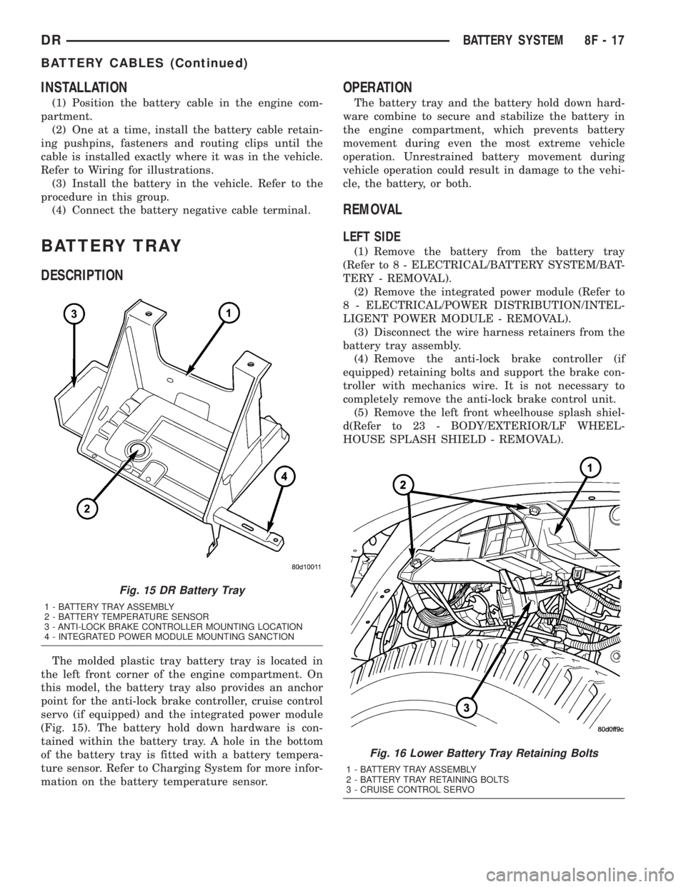
The molded plastic tray battery tray is located in
the left front corner of the engine compartment. On
this model, the battery tray also provides an anchor
point for the anti-lock brake controller, cruise control
servo (if equipped) and the integrated power module
(Fig. 15). The battery hold down hardware is con-
tained within the battery tray. A hole in the bottom
of the battery tray is fitted with a battery tempera-
ture sensor. Refer to Charging System for more infor-
mation on the battery temperature sensor.
OPERATION
The battery tray and the battery hold down hard-
ware combine to secure and stabilize the battery in
the engine compartment, which prevents battery
movement during even the most extreme vehicle
operation. Unrestrained battery movement during
vehicle operation could result in damage to the vehi-
cle, the battery, or both.
REMOVAL
LEFT SIDE
(1) Remove the battery from the battery tray
(Refer to 8 - ELECTRICAL/BATTERY SYSTEM/BAT-
TERY - REMOVAL).
(2) Remove the integrated power module (Refer to
8 - ELECTRICAL/POWER DISTRIBUTION/INTEL-
LIGENT POWER MODULE - REMOVAL).
(3) Disconnect the wire harness retainers from the
battery tray assembly.
(4) Remove the anti-lock brake controller (if
equipped) retaining bolts and support the brake con-
troller with mechanics wire. It is not necessary to
completely remove the anti-lock brake control unit.
(5) Remove the left front wheelhouse splash shiel-
d(Refer to 23 - BODY/EXTERIOR/LF WHEEL-
HOUSE SPLASH SHIELD - REMOVAL).
Fig. 15 DR Battery Tray
1 - BATTERY TRAY ASSEMBLY
2 - BATTERY TEMPERATURE SENSOR
3 - ANTI-LOCK BRAKE CONTROLLER MOUNTING LOCATION
4 - INTEGRATED POWER MODULE MOUNTING SANCTION
Fig. 16 Lower Battery Tray Retaining Bolts
1 - BATTERY TRAY ASSEMBLY
2 - BATTERY TRAY RETAINING BOLTS
3 - CRUISE CONTROL SERVO
DRBATTERY SYSTEM 8F - 17
BATTERY CABLES (Continued)
Page 426 of 2895
DESCRIPTION N´m Ft. Lbs. In. Lbs.
Generator Lower Pivot Bolt / Nut -
5.9L Gas Engine41 30 -
Generator Vertical Mounting Bolt -
3.7L / 4.7L Engines55 40 -
Generator (long) Horizontal
Mounting Bolt - 3.7L / 4.7L Engines55 40 -
Generator (short) Horizontal
Mounting Bolt - 3.7L / 4.7L Engines74 55 -
Generator B+ Output Cable
Terminal Nut12 - 108
BATTERY TEMPERATURE
SENSOR
DESCRIPTION
The Battery Temperature Sensor (BTS) is attached
to the battery tray located under the battery.
OPERATION
The BTS is used to determine the battery temper-
ature and control battery charging rate. This temper-
ature data, along with data from monitored line
voltage, is used by the PCM (ECM Diesel) to vary the
battery charging rate. System voltage will be higher
at colder temperatures and is gradually reduced at
warmer temperatures.
The PCM sends 5 volts to the sensor and is
grounded through the sensor return line. As temper-
ature increases, resistance in the sensor decreases
and the detection voltage at the PCM increases.
The BTS is also used for OBD II diagnostics. Cer-
tain faults and OBD II monitors are either enabled
or disabled, depending upon BTS input (for example,
disable purge and enable Leak Detection Pump
(LDP) and O2 sensor heater tests). Most OBD II
monitors are disabled below 20ÉF.
REMOVAL
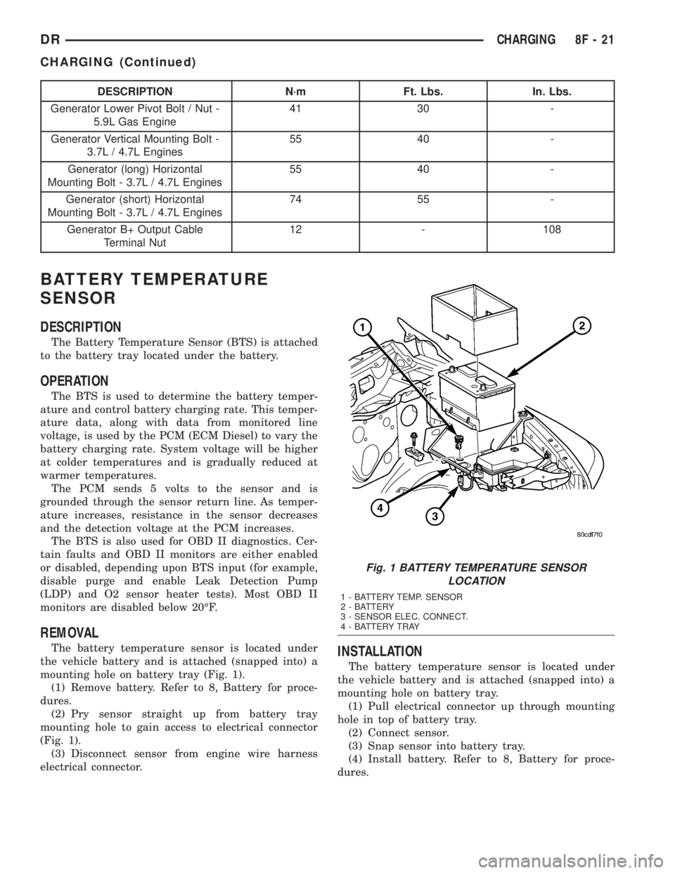
The battery temperature sensor is located under
the vehicle battery and is attached (snapped into) a
mounting hole on battery tray (Fig. 1).
(1) Remove battery. Refer to 8, Battery for proce-
dures.
(2) Pry sensor straight up from battery tray
mounting hole to gain access to electrical connector
(Fig. 1).
(3) Disconnect sensor from engine wire harness
electrical connector.INSTALLATION
The battery temperature sensor is located under
the vehicle battery and is attached (snapped into) a
mounting hole on battery tray.
(1) Pull electrical connector up through mounting
hole in top of battery tray.
(2) Connect sensor.
(3) Snap sensor into battery tray.
(4) Install battery. Refer to 8, Battery for proce-
dures.
Fig. 1 BATTERY TEMPERATURE SENSOR
LOCATION
1 - BATTERY TEMP. SENSOR
2 - BATTERY
3 - SENSOR ELEC. CONNECT.
4 - BATTERY TRAY
DRCHARGING 8F - 21
CHARGING (Continued)
Page 433 of 2895
STARTING
TABLE OF CONTENTS
page page
STARTING
DESCRIPTION.........................28
OPERATION...........................28
DIAGNOSIS AND TESTING - STARTING
SYSTEM............................29
SPECIFICATIONS
STARTING SYSTEM...................33
SPECIFICATIONS - TORQUE - STARTING
SYSTEM............................34
STARTER MOTOR
DIAGNOSIS AND TESTING - STARTER
MOTOR .............................34REMOVAL.............................34
INSTALLATION.........................37
STARTER MOTOR RELAY
DESCRIPTION.........................38
OPERATION...........................38
DIAGNOSIS AND TESTING - STARTER RELAY . 38
REMOVAL.............................39
INSTALLATION.........................39
STARTING
DESCRIPTION
The starting system consists of:
²Starter relay
²Starter motor (including an integral starter sole-
noid)
Other components to be considered as part of start-
ing system are:
²Battery
²Battery cables
²Ignition switch and key lock cylinder
²Clutch pedal position switch (manual transmis-
sion)
²Park/neutral position switch (automatic trans-
mission)
²Wire harnesses and connections.
The Battery, Starting, and Charging systems oper-
ate in conjunction with one another, and must be
tested as a complete system. For correct operation of
starting/charging systems, all components used in
these 3 systems must perform within specifications.
When attempting to diagnose any of these systems, it
is important that you keep their interdependency in
mind.
The diagnostic procedures used in each of these
groups include the most basic conventional diagnostic
methods, to the more sophisticated On-Board Diag-
nostics (OBD) built into the Powertrain Control Mod-
ule (PCM). Use of an induction-type milliampere
ammeter, volt/ohmmeter, battery charger, carbon pile
rheostat (load tester), and 12-volt test lamp may be
required.
Certain starting system components are monitored
by the PCM and may produce a Diagnostic TroubleCode (DTC). Refer to Diagnostic Trouble Codes in
Emission Control for a list of codes.OPERATION
The starting system components form two separate
circuits. A high-amperage feed circuit that feeds the
starter motor between 150 and 350 amperes (700
amperes - diesel engine), and a low-amperage control
circuit that operates on less than 20 amperes. The
high-amperage feed circuit components include the
battery, the battery cables, the contact disc portion of
the starter solenoid, and the starter motor. The low-
amperage control circuit components include the igni-
tion switch, the clutch pedal position switch (manual
transmission), the park/neutral position switch (auto-
matic transmission), the starter relay, the electro-
magnetic windings of the starter solenoid, and the
connecting wire harness components.
If the vehicle is equipped with a manual transmis-
sion, it has a clutch pedal position switch installed in
series between the ignition switch and the coil bat-
tery terminal of the starter relay. This normally open
switch prevents the starter relay from being ener-
gized when the ignition switch is turned to the Start
position, unless the clutch pedal is depressed. This
feature prevents starter motor operation while the
clutch disc and the flywheel are engaged. The starter
relay coil ground terminal is always grounded on
vehicles with a manual transmission.
If the vehicle is equipped with an automatic trans-
mission, battery voltage is supplied through the low-
amperage control circuit to the coil battery terminal
of the starter relay when the ignition switch is
turned to the Start position. The park/neutral posi-
tion switch is installed in series between the starter
relay coil ground terminal and ground. This normally
8F - 28 STARTINGDR
Page 435 of 2895
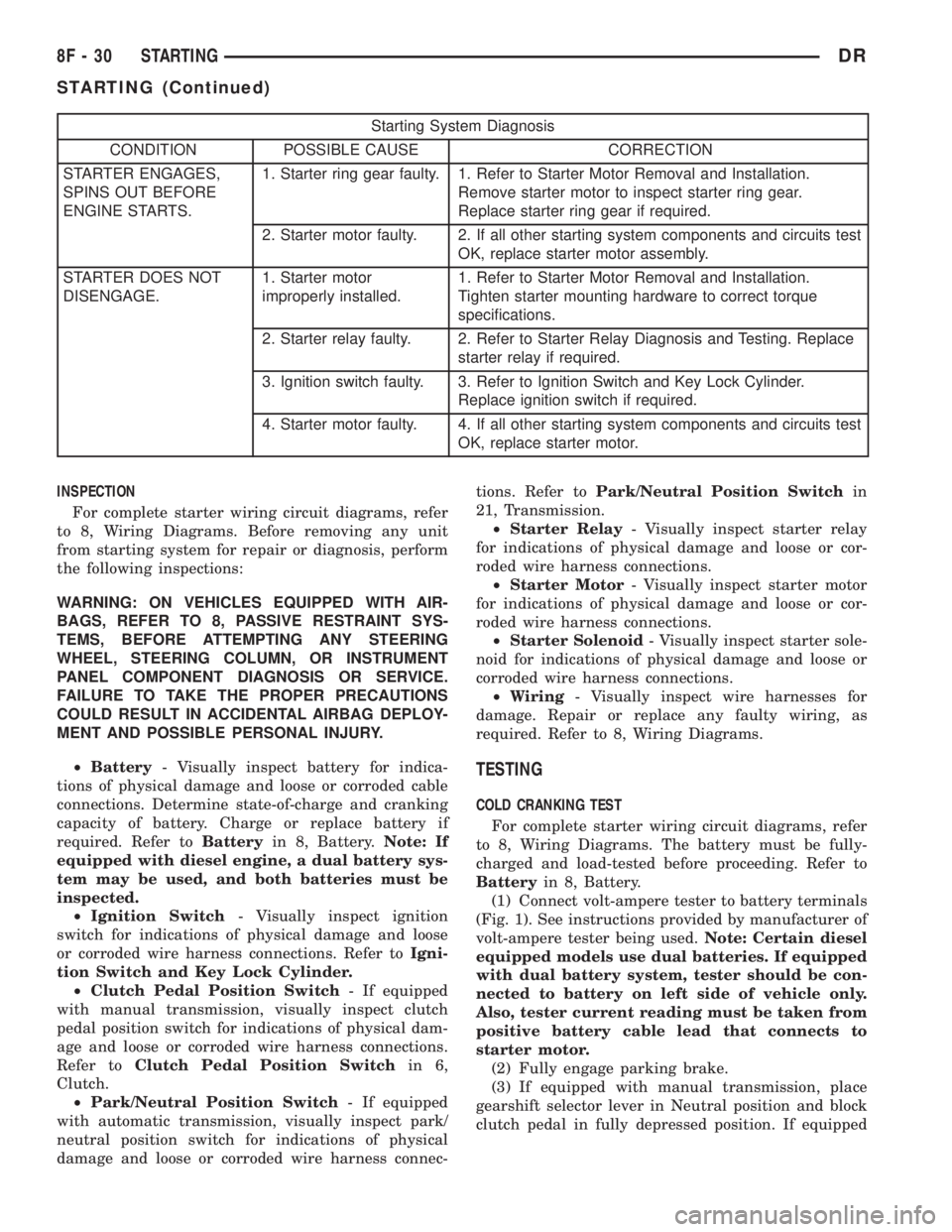
Starting System Diagnosis
CONDITION POSSIBLE CAUSE CORRECTION
STARTER ENGAGES,
SPINS OUT BEFORE
ENGINE STARTS.1. Starter ring gear faulty. 1. Refer to Starter Motor Removal and Installation.
Remove starter motor to inspect starter ring gear.
Replace starter ring gear if required.
2. Starter motor faulty. 2. If all other starting system components and circuits test
OK, replace starter motor assembly.
STARTER DOES NOT
DISENGAGE.1. Starter motor
improperly installed.1. Refer to Starter Motor Removal and Installation.
Tighten starter mounting hardware to correct torque
specifications.
2. Starter relay faulty. 2. Refer to Starter Relay Diagnosis and Testing. Replace
starter relay if required.
3. Ignition switch faulty. 3. Refer to Ignition Switch and Key Lock Cylinder.
Replace ignition switch if required.
4. Starter motor faulty. 4. If all other starting system components and circuits test
OK, replace starter motor.
INSPECTION
For complete starter wiring circuit diagrams, refer
to 8, Wiring Diagrams. Before removing any unit
from starting system for repair or diagnosis, perform
the following inspections:
WARNING: ON VEHICLES EQUIPPED WITH AIR-
BAGS, REFER TO 8, PASSIVE RESTRAINT SYS-
TEMS, BEFORE ATTEMPTING ANY STEERING
WHEEL, STEERING COLUMN, OR INSTRUMENT
PANEL COMPONENT DIAGNOSIS OR SERVICE.
FAILURE TO TAKE THE PROPER PRECAUTIONS
COULD RESULT IN ACCIDENTAL AIRBAG DEPLOY-
MENT AND POSSIBLE PERSONAL INJURY.
²Battery- Visually inspect battery for indica-
tions of physical damage and loose or corroded cable
connections. Determine state-of-charge and cranking
capacity of battery. Charge or replace battery if
required. Refer toBatteryin 8, Battery.Note: If
equipped with diesel engine, a dual battery sys-
tem may be used, and both batteries must be
inspected.
²Ignition Switch- Visually inspect ignition
switch for indications of physical damage and loose
or corroded wire harness connections. Refer toIgni-
tion Switch and Key Lock Cylinder.
²Clutch Pedal Position Switch- If equipped
with manual transmission, visually inspect clutch
pedal position switch for indications of physical dam-
age and loose or corroded wire harness connections.
Refer toClutch Pedal Position Switchin 6,
Clutch.
²Park/Neutral Position Switch- If equipped
with automatic transmission, visually inspect park/
neutral position switch for indications of physical
damage and loose or corroded wire harness connec-tions. Refer toPark/Neutral Position Switchin
21, Transmission.
²Starter Relay- Visually inspect starter relay
for indications of physical damage and loose or cor-
roded wire harness connections.
²Starter Motor- Visually inspect starter motor
for indications of physical damage and loose or cor-
roded wire harness connections.
²Starter Solenoid- Visually inspect starter sole-
noid for indications of physical damage and loose or
corroded wire harness connections.
²Wiring- Visually inspect wire harnesses for
damage. Repair or replace any faulty wiring, as
required. Refer to 8, Wiring Diagrams.
TESTING
COLD CRANKING TEST
For complete starter wiring circuit diagrams, refer
to 8, Wiring Diagrams. The battery must be fully-
charged and load-tested before proceeding. Refer to
Batteryin 8, Battery.
(1) Connect volt-ampere tester to battery terminals
(Fig. 1). See instructions provided by manufacturer of
volt-ampere tester being used.Note: Certain diesel
equipped models use dual batteries. If equipped
with dual battery system, tester should be con-
nected to battery on left side of vehicle only.
Also, tester current reading must be taken from
positive battery cable lead that connects to
starter motor.
(2) Fully engage parking brake.
(3) If equipped with manual transmission, place
gearshift selector lever in Neutral position and block
clutch pedal in fully depressed position. If equipped
8F - 30 STARTINGDR
STARTING (Continued)
Page 438 of 2895
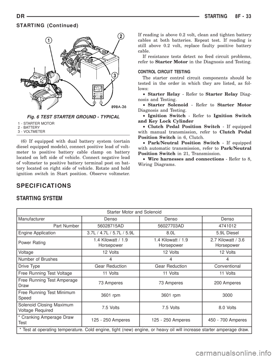
(6) If equipped with dual battery system (certain
diesel equipped models), connect positive lead of volt-
meter to positive battery cable clamp on battery
located on left side of vehicle. Connect negative lead
of voltmeter to positive battery terminal post on bat-
tery located on right side of vehicle. Rotate and hold
ignition switch in Start position. Observe voltmeter.If reading is above 0.2 volt, clean and tighten battery
cables at both batteries. Repeat test. If reading is
still above 0.2 volt, replace faulty positive battery
cable.
If resistance tests detect no feed circuit problems,
refer toStarter Motorin the Diagnosis and Testing.
CONTROL CIRCUIT TESTING
The starter control circuit components should be
tested in the order in which they are listed, as fol-
lows:
²Starter Relay- Refer toStarter RelayDiag-
nosis and Testing.
²Starter Solenoid- Refer toStarter Motor
Diagnosis and Testing.
²Ignition Switch- Refer toIgnition Switch
and Key Lock Cylinder
²Clutch Pedal Position Switch- If equipped
with manual transmission, refer toClutch Pedal
Position Switchin 6, Clutch.
²Park/Neutral Position Switch- If equipped
with automatic transmission, refer toPark/Neutral
Position Switchin 21, Transmission.
²Wire harnesses and connections- Refer to 8,
Wiring Diagrams.
SPECIFICATIONS
STARTING SYSTEM
Starter Motor and Solenoid
Manufacturer Denso Denso Denso
Part Number 56028715AD 56027703AD 4741012
Engine Application 3.7L / 4.7L / 5.7L / 5.9L 8.0L 5.9L Diesel
Power Rating1.4 Kilowatt / 1.9
Horsepower1.4 Kilowatt / 1.9
Horsepower2.7 Kilowatt / 3.6
Horsepower
Voltage 12 Volts 12 Volts 12 Volts
Number of Brushes 4 4 4
Drive Type Gear Reduction Gear Reduction Conventional
Free Running Test Voltage 11 Volts 11 Volts 11 Volts
Free Running Test Amperage
Draw73 Amperes 73 Amperes 200 Amperes
Free Running Test Minimum
Speed3601 rpm 3601 rpm 3000
Solenoid Closing Maximum
Voltage Required7.5 Volts 7.5 Volts 8.0 Volts
* Cranking Amperage Draw
Test125 - 250 Amperes 125 - 250 Amperes 450 - 700 Amperes
* Test at operating temperature. Cold engine, tight (new) engine, or heavy oil will increase starter amperage draw.
Fig. 6 TEST STARTER GROUND - TYPICAL
1 - STARTER MOTOR
2 - BATTERY
3 - VOLTMETER
DRSTARTING 8F - 33
STARTING (Continued)