DODGE RAM 2003 Service Repair Manual
Manufacturer: DODGE, Model Year: 2003, Model line: RAM, Model: DODGE RAM 2003Pages: 2895, PDF Size: 83.15 MB
Page 1721 of 2895
FUEL INJECTION - GAS
TABLE OF CONTENTS
page page
ACCELERATOR PEDAL
REMOVAL.............................24
INSTALLATION.........................24
ACCELERATOR PEDAL POSITION SENSOR
DESCRIPTION.........................25
OPERATION...........................25
REMOVAL.............................25
INSTALLATION.........................25
CRANKSHAFT POSITION SENSOR
DESCRIPTION.........................26
OPERATION...........................26
REMOVAL.............................29
INSTALLATION.........................30
FUEL INJECTOR
DESCRIPTION.........................32
OPERATION
OPERATION - FUEL INJECTOR..........32
OPERATION - PCM OUTPUT............32
REMOVAL.............................32
INSTALLATION.........................33
FUEL PUMP RELAY
DESCRIPTION.........................33
OPERATION...........................33
REMOVAL.............................33
INSTALLATION.........................33
IDLE AIR CONTROL MOTOR
DESCRIPTION.........................33
OPERATION...........................33
REMOVAL.............................34INSTALLATION.........................35
INTAKE AIR TEMPERATURE SENSOR
DESCRIPTION.........................36
OPERATION...........................36
REMOVAL.............................36
INSTALLATION.........................38
MAP SENSOR
DESCRIPTION.........................39
OPERATION...........................39
REMOVAL.............................40
INSTALLATION.........................42
OXYGEN SENSOR
DESCRIPTION.........................43
OPERATION...........................43
REMOVAL.............................44
INSTALLATION.........................45
THROTTLE BODY
DESCRIPTION.........................45
OPERATION...........................45
REMOVAL.............................45
INSTALLATION.........................47
THROTTLE CONTROL CABLE
REMOVAL.............................49
INSTALLATION.........................51
THROTTLE POSITION SENSOR
DESCRIPTION.........................52
OPERATION...........................52
REMOVAL.............................53
INSTALLATION.........................54
ACCELERATOR PEDAL
REMOVAL
The following procedure applies only to vehicles
without the Adjustable Pedal Package (code XAP).
The accelerator pedal is serviced as a complete
assembly including the bracket.
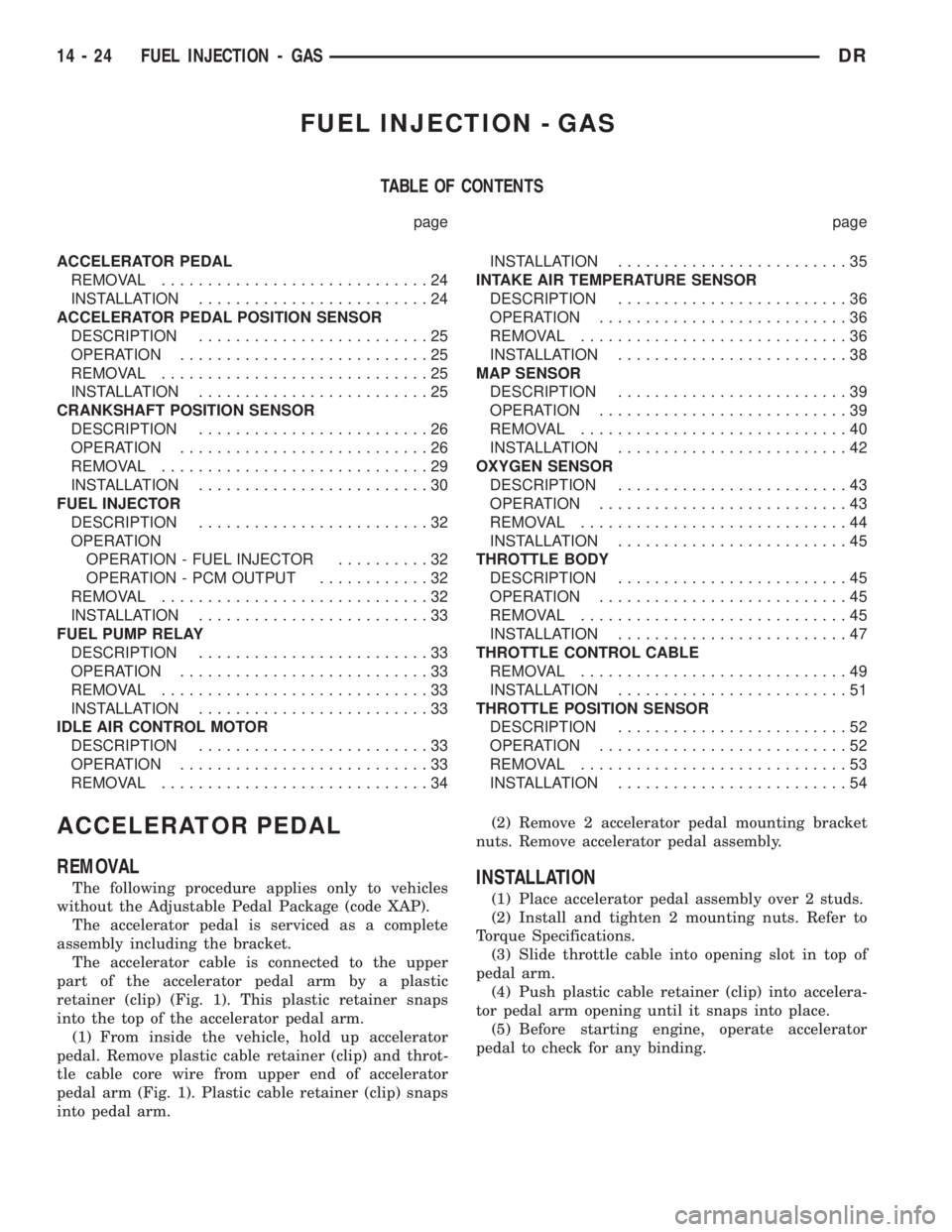
The accelerator cable is connected to the upper
part of the accelerator pedal arm by a plastic
retainer (clip) (Fig. 1). This plastic retainer snaps
into the top of the accelerator pedal arm.
(1) From inside the vehicle, hold up accelerator
pedal. Remove plastic cable retainer (clip) and throt-
tle cable core wire from upper end of accelerator
pedal arm (Fig. 1). Plastic cable retainer (clip) snaps
into pedal arm.(2) Remove 2 accelerator pedal mounting bracket
nuts. Remove accelerator pedal assembly.INSTALLATION
(1) Place accelerator pedal assembly over 2 studs.
(2) Install and tighten 2 mounting nuts. Refer to
Torque Specifications.
(3) Slide throttle cable into opening slot in top of
pedal arm.
(4) Push plastic cable retainer (clip) into accelera-
tor pedal arm opening until it snaps into place.
(5) Before starting engine, operate accelerator
pedal to check for any binding.
14 - 24 FUEL INJECTION - GASDR
Page 1722 of 2895
ACCELERATOR PEDAL
POSITION SENSOR
DESCRIPTION
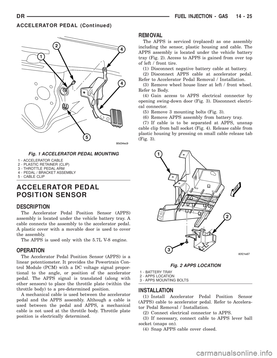
The Accelerator Pedal Position Sensor (APPS)
assembly is located under the vehicle battery tray. A
cable connects the assembly to the accelerator pedal.
A plastic cover with a movable door is used to cover
the assembly.
The APPS is used only with the 5.7L V-8 engine.
OPERATION
The Accelerator Pedal Position Sensor (APPS) is a
linear potentiometer. It provides the Powertrain Con-
trol Module (PCM) with a DC voltage signal propor-
tional to the angle, or position of the accelerator
pedal. The APPS signal is translated (along with
other sensors) to place the throttle plate (within the
throttle body) to a pre-determined position.
A mechanical cable is used between the accelerator
pedal and the APPS assembly. Although a cable is
used between the pedal and APPS, a mechanical
cable is not used at the throttle body. Throttle plate
position is electrically determined.
REMOVAL
The APPS is serviced (replaced) as one assembly
including the sensor, plastic housing and cable. The
APPS assembly is located under the vehicle battery
tray (Fig. 2). Access to APPS is gained from over top
of left / front tire.
(1) Disconnect negative battery cable at battery.
(2) Disconnect APPS cable at accelerator pedal.
Refer to Accelerator Pedal Removal / Installation.
(3) Remove wheel house liner at left / front wheel.
Refer to Body.
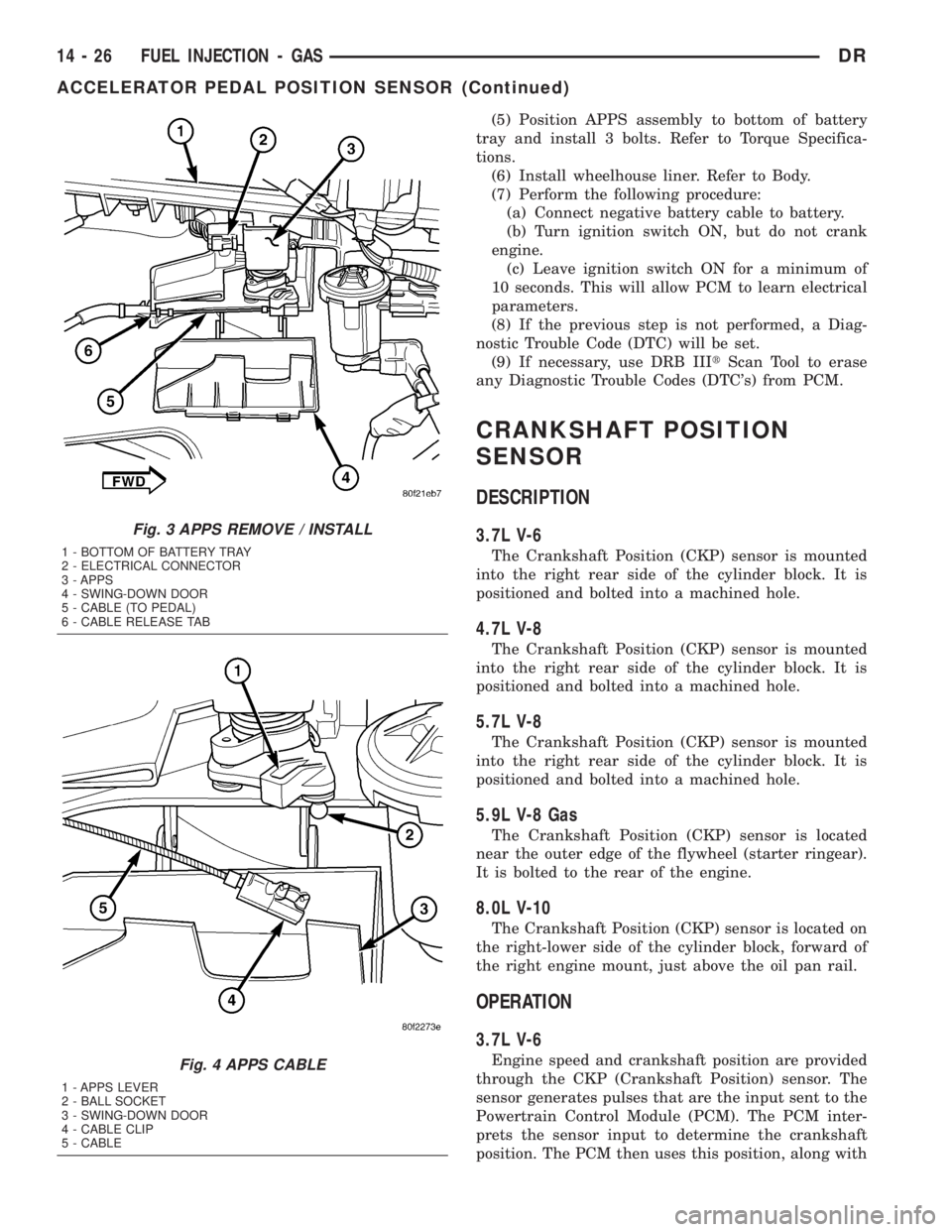
(4) Gain access to APPS electrical connector by
opening swing-down door (Fig. 3). Disconnect electri-
cal connector.
(5) Remove 3 mounting bolts (Fig. 3).
(6) Remove APPS assembly from battery tray.
(7) If cable is to be separated at APPS, unsnap
cable clip from ball socket (Fig. 4). Release cable from
plastic housing by pressing on small cable release tab
(Fig. 3).
INSTALLATION
(1) Install Accelerator Pedal Position Sensor
(APPS) cable to accelerator pedal. Refer to Accelera-
tor Pedal Removal / Installation.
(2) Connect electrical connector to APPS.
(3) If necessary, connect cable to APPS lever ball
socket (snaps on).
(4) Snap APPS cable cover closed.
Fig. 1 ACCELERATOR PEDAL MOUNTING
1 - ACCELERATOR CABLE
2 - PLASTIC RETAINER (CLIP)
3 - THROTTLE PEDAL ARM
4 - PEDAL / BRACKET ASSEMBLY
5 - CABLE CLIP
Fig. 2 APPS LOCATION
1 - BATTERY TRAY
2 - APPS LOCATION
3 - APPS MOUNTING BOLTS
DRFUEL INJECTION - GAS 14 - 25
ACCELERATOR PEDAL (Continued)
Page 1723 of 2895
(5) Position APPS assembly to bottom of battery
tray and install 3 bolts. Refer to Torque Specifica-
tions.
(6) Install wheelhouse liner. Refer to Body.
(7) Perform the following procedure:
(a) Connect negative battery cable to battery.
(b) Turn ignition switch ON, but do not crank
engine.
(c) Leave ignition switch ON for a minimum of
10 seconds. This will allow PCM to learn electrical
parameters.
(8) If the previous step is not performed, a Diag-
nostic Trouble Code (DTC) will be set.
(9) If necessary, use DRB IIItScan Tool to erase
any Diagnostic Trouble Codes (DTC's) from PCM.
CRANKSHAFT POSITION
SENSOR
DESCRIPTION
3.7L V-6
The Crankshaft Position (CKP) sensor is mounted
into the right rear side of the cylinder block. It is
positioned and bolted into a machined hole.
4.7L V-8
The Crankshaft Position (CKP) sensor is mounted
into the right rear side of the cylinder block. It is
positioned and bolted into a machined hole.
5.7L V-8
The Crankshaft Position (CKP) sensor is mounted
into the right rear side of the cylinder block. It is
positioned and bolted into a machined hole.
5.9L V-8 Gas
The Crankshaft Position (CKP) sensor is located
near the outer edge of the flywheel (starter ringear).
It is bolted to the rear of the engine.
8.0L V-10
The Crankshaft Position (CKP) sensor is located on
the right-lower side of the cylinder block, forward of
the right engine mount, just above the oil pan rail.
OPERATION
3.7L V-6
Engine speed and crankshaft position are provided
through the CKP (Crankshaft Position) sensor. The
sensor generates pulses that are the input sent to the
Powertrain Control Module (PCM). The PCM inter-
prets the sensor input to determine the crankshaft
position. The PCM then uses this position, along with
Fig. 3 APPS REMOVE / INSTALL
1 - BOTTOM OF BATTERY TRAY
2 - ELECTRICAL CONNECTOR
3 - APPS
4 - SWING-DOWN DOOR
5 - CABLE (TO PEDAL)
6 - CABLE RELEASE TAB
Fig. 4 APPS CABLE
1 - APPS LEVER
2 - BALL SOCKET
3 - SWING-DOWN DOOR
4 - CABLE CLIP
5 - CABLE
14 - 26 FUEL INJECTION - GASDR
ACCELERATOR PEDAL POSITION SENSOR (Continued)
Page 1724 of 2895
other inputs, to determine injector sequence and igni-
tion timing.
The sensor is a hall effect device combined with an
internal magnet. It is also sensitive to steel within a
certain distance from it.
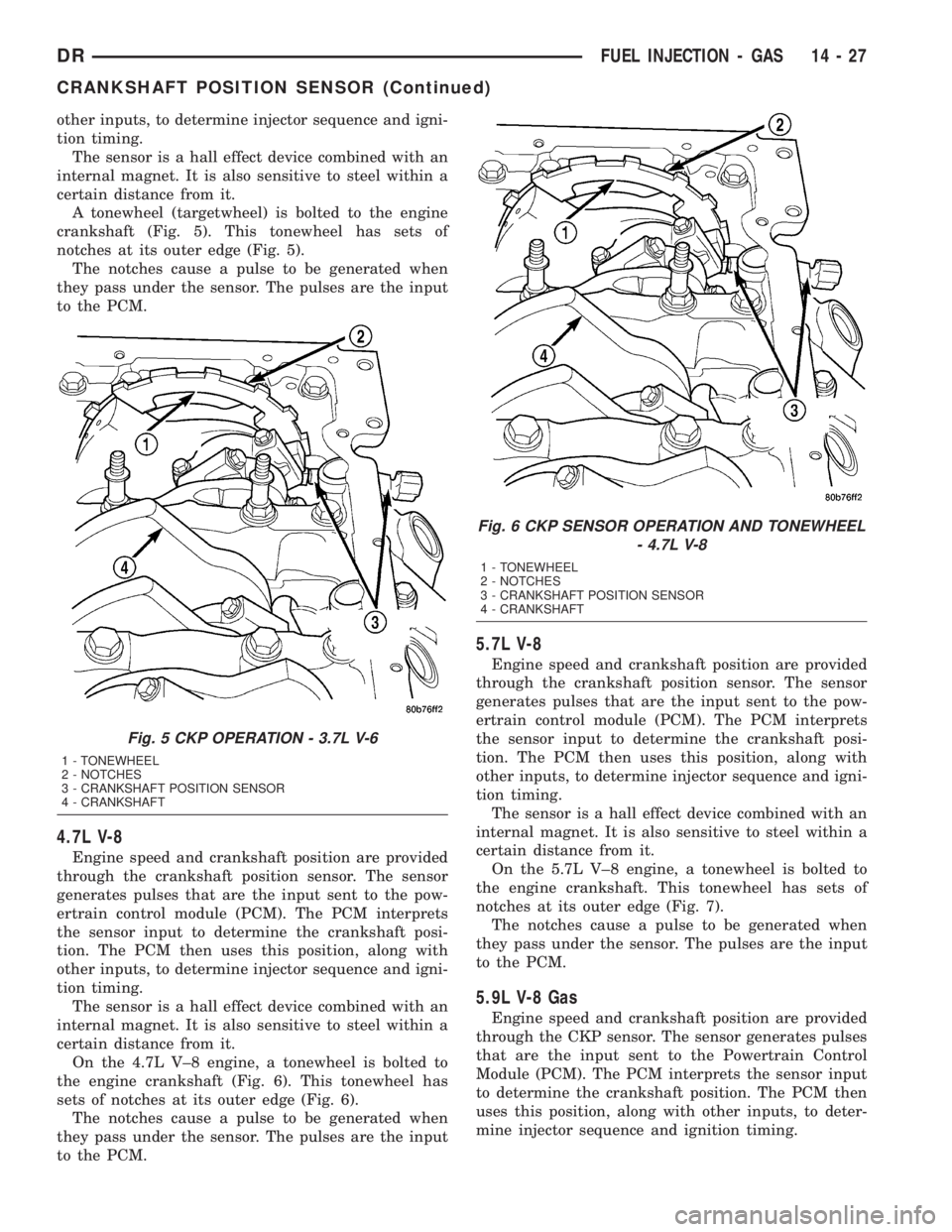
A tonewheel (targetwheel) is bolted to the engine
crankshaft (Fig. 5). This tonewheel has sets of
notches at its outer edge (Fig. 5).
The notches cause a pulse to be generated when
they pass under the sensor. The pulses are the input
to the PCM.
4.7L V-8
Engine speed and crankshaft position are provided
through the crankshaft position sensor. The sensor
generates pulses that are the input sent to the pow-
ertrain control module (PCM). The PCM interprets
the sensor input to determine the crankshaft posi-
tion. The PCM then uses this position, along with
other inputs, to determine injector sequence and igni-
tion timing.
The sensor is a hall effect device combined with an
internal magnet. It is also sensitive to steel within a
certain distance from it.
On the 4.7L V±8 engine, a tonewheel is bolted to
the engine crankshaft (Fig. 6). This tonewheel has
sets of notches at its outer edge (Fig. 6).
The notches cause a pulse to be generated when
they pass under the sensor. The pulses are the input
to the PCM.
5.7L V-8
Engine speed and crankshaft position are provided
through the crankshaft position sensor. The sensor
generates pulses that are the input sent to the pow-
ertrain control module (PCM). The PCM interprets
the sensor input to determine the crankshaft posi-
tion. The PCM then uses this position, along with
other inputs, to determine injector sequence and igni-
tion timing.
The sensor is a hall effect device combined with an
internal magnet. It is also sensitive to steel within a
certain distance from it.
On the 5.7L V±8 engine, a tonewheel is bolted to
the engine crankshaft. This tonewheel has sets of
notches at its outer edge (Fig. 7).
The notches cause a pulse to be generated when
they pass under the sensor. The pulses are the input
to the PCM.
5.9L V-8 Gas
Engine speed and crankshaft position are provided
through the CKP sensor. The sensor generates pulses
that are the input sent to the Powertrain Control
Module (PCM). The PCM interprets the sensor input
to determine the crankshaft position. The PCM then
uses this position, along with other inputs, to deter-
mine injector sequence and ignition timing.
Fig. 5 CKP OPERATION - 3.7L V-6
1 - TONEWHEEL
2 - NOTCHES
3 - CRANKSHAFT POSITION SENSOR
4 - CRANKSHAFT
Fig. 6 CKP SENSOR OPERATION AND TONEWHEEL
- 4.7L V-8
1 - TONEWHEEL
2 - NOTCHES
3 - CRANKSHAFT POSITION SENSOR
4 - CRANKSHAFT
DRFUEL INJECTION - GAS 14 - 27
CRANKSHAFT POSITION SENSOR (Continued)
Page 1725 of 2895
The sensor is a hall effect device combined with an
internal magnet. It is also sensitive to steel within a
certain distance from it.
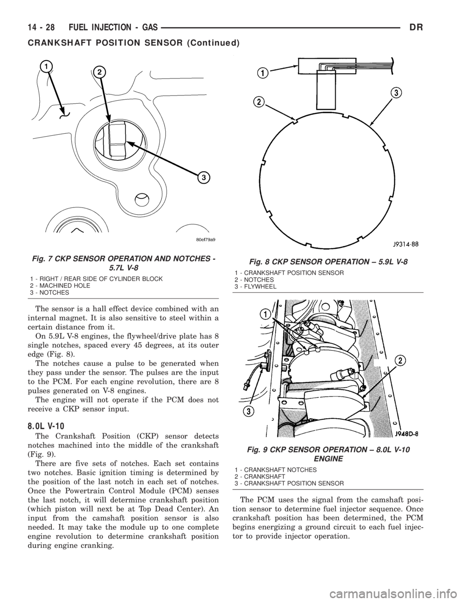
On 5.9L V-8 engines, the flywheel/drive plate has 8
single notches, spaced every 45 degrees, at its outer
edge (Fig. 8).
The notches cause a pulse to be generated when
they pass under the sensor. The pulses are the input
to the PCM. For each engine revolution, there are 8
pulses generated on V-8 engines.
The engine will not operate if the PCM does not
receive a CKP sensor input.
8.0L V-10
The Crankshaft Position (CKP) sensor detects
notches machined into the middle of the crankshaft
(Fig. 9).
There are five sets of notches. Each set contains
two notches. Basic ignition timing is determined by
the position of the last notch in each set of notches.
Once the Powertrain Control Module (PCM) senses
the last notch, it will determine crankshaft position
(which piston will next be at Top Dead Center). An
input from the camshaft position sensor is also
needed. It may take the module up to one complete
engine revolution to determine crankshaft position
during engine cranking.The PCM uses the signal from the camshaft posi-
tion sensor to determine fuel injector sequence. Once
crankshaft position has been determined, the PCM
begins energizing a ground circuit to each fuel injec-
tor to provide injector operation.
Fig. 7 CKP SENSOR OPERATION AND NOTCHES -
5.7L V-8
1 - RIGHT / REAR SIDE OF CYLINDER BLOCK
2 - MACHINED HOLE
3 - NOTCHES
Fig. 8 CKP SENSOR OPERATION ± 5.9L V-8
1 - CRANKSHAFT POSITION SENSOR
2 - NOTCHES
3 - FLYWHEEL
Fig. 9 CKP SENSOR OPERATION ± 8.0L V-10
ENGINE
1 - CRANKSHAFT NOTCHES
2 - CRANKSHAFT
3 - CRANKSHAFT POSITION SENSOR
14 - 28 FUEL INJECTION - GASDR
CRANKSHAFT POSITION SENSOR (Continued)
Page 1726 of 2895
REMOVAL
3.7L V-6
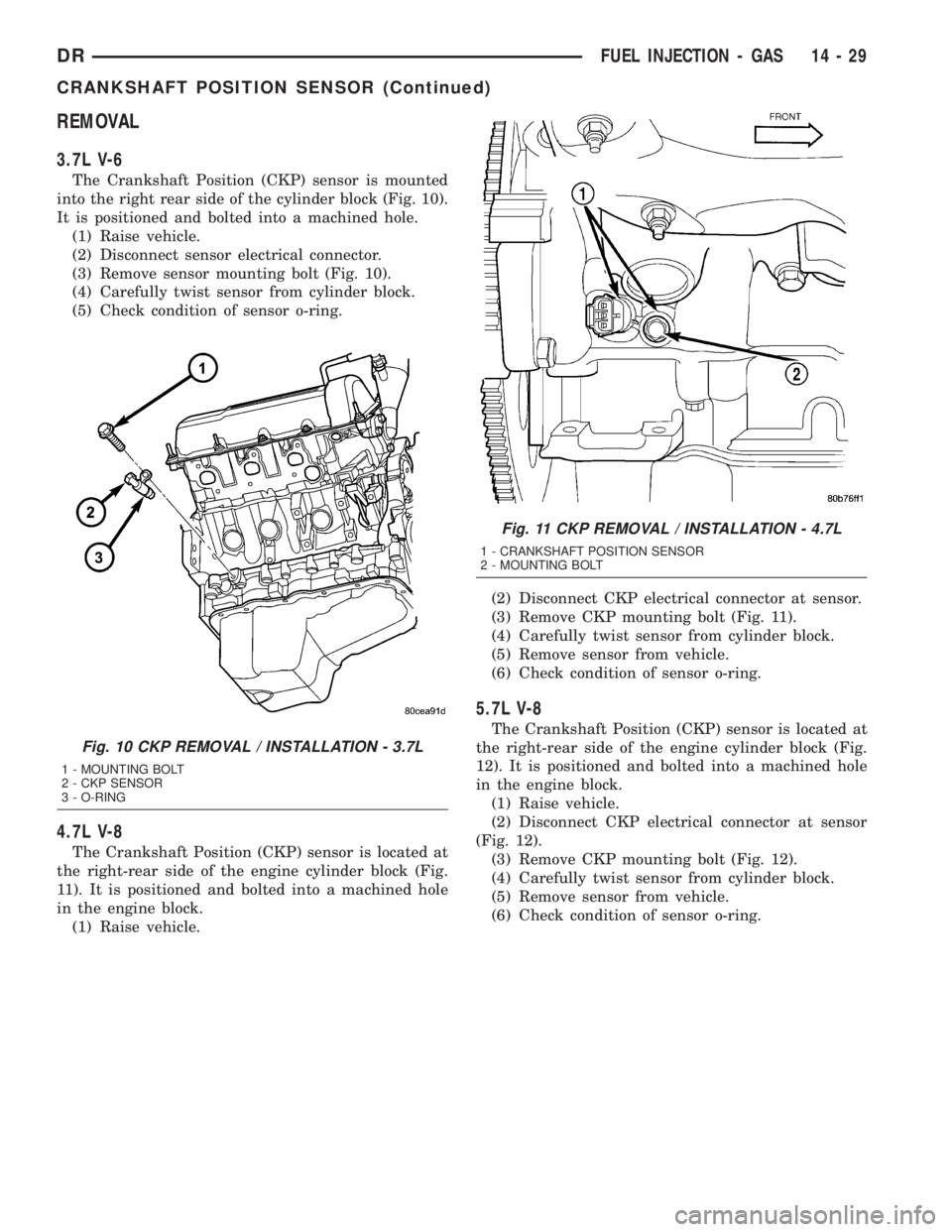
The Crankshaft Position (CKP) sensor is mounted
into the right rear side of the cylinder block (Fig. 10).
It is positioned and bolted into a machined hole.
(1) Raise vehicle.
(2) Disconnect sensor electrical connector.
(3) Remove sensor mounting bolt (Fig. 10).
(4) Carefully twist sensor from cylinder block.
(5) Check condition of sensor o-ring.
4.7L V-8
The Crankshaft Position (CKP) sensor is located at
the right-rear side of the engine cylinder block (Fig.
11). It is positioned and bolted into a machined hole
in the engine block.
(1) Raise vehicle.(2) Disconnect CKP electrical connector at sensor.
(3) Remove CKP mounting bolt (Fig. 11).
(4) Carefully twist sensor from cylinder block.
(5) Remove sensor from vehicle.
(6) Check condition of sensor o-ring.
5.7L V-8
The Crankshaft Position (CKP) sensor is located at
the right-rear side of the engine cylinder block (Fig.
12). It is positioned and bolted into a machined hole
in the engine block.
(1) Raise vehicle.
(2) Disconnect CKP electrical connector at sensor
(Fig. 12).
(3) Remove CKP mounting bolt (Fig. 12).
(4) Carefully twist sensor from cylinder block.
(5) Remove sensor from vehicle.
(6) Check condition of sensor o-ring.
Fig. 10 CKP REMOVAL / INSTALLATION - 3.7L
1 - MOUNTING BOLT
2 - CKP SENSOR
3 - O-RING
Fig. 11 CKP REMOVAL / INSTALLATION - 4.7L
1 - CRANKSHAFT POSITION SENSOR
2 - MOUNTING BOLT
DRFUEL INJECTION - GAS 14 - 29
CRANKSHAFT POSITION SENSOR (Continued)
Page 1727 of 2895
5.9L Gas
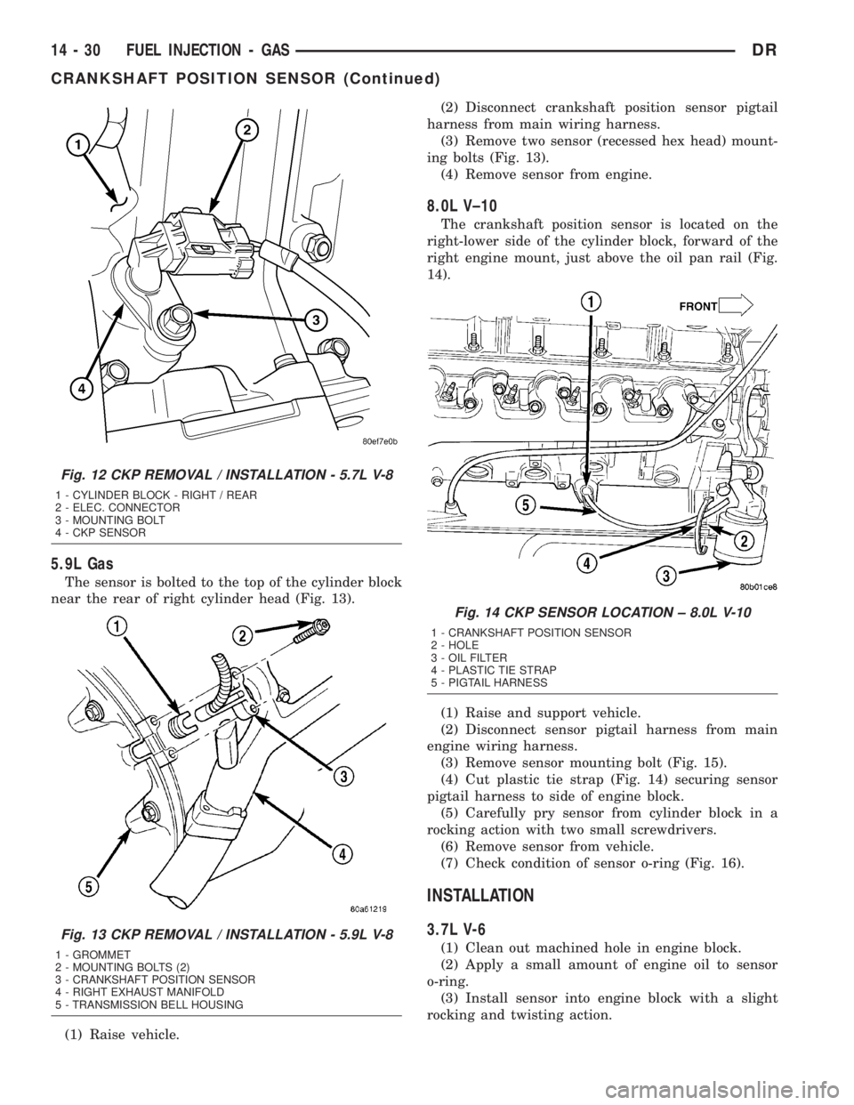
The sensor is bolted to the top of the cylinder block
near the rear of right cylinder head (Fig. 13).
(1) Raise vehicle.(2) Disconnect crankshaft position sensor pigtail
harness from main wiring harness.
(3) Remove two sensor (recessed hex head) mount-
ing bolts (Fig. 13).
(4) Remove sensor from engine.
8.0L V±10
The crankshaft position sensor is located on the
right-lower side of the cylinder block, forward of the
right engine mount, just above the oil pan rail (Fig.
14).
(1) Raise and support vehicle.
(2) Disconnect sensor pigtail harness from main
engine wiring harness.
(3) Remove sensor mounting bolt (Fig. 15).
(4) Cut plastic tie strap (Fig. 14) securing sensor
pigtail harness to side of engine block.
(5) Carefully pry sensor from cylinder block in a
rocking action with two small screwdrivers.
(6) Remove sensor from vehicle.
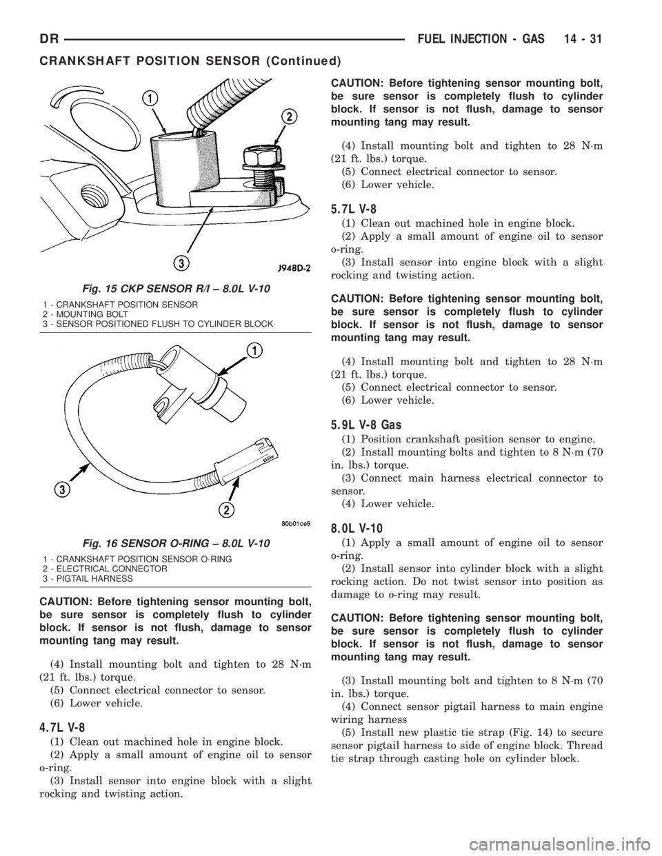
(7) Check condition of sensor o-ring (Fig. 16).
INSTALLATION
3.7L V-6
(1) Clean out machined hole in engine block.
(2) Apply a small amount of engine oil to sensor
o-ring.
(3) Install sensor into engine block with a slight
rocking and twisting action.
Fig. 12 CKP REMOVAL / INSTALLATION - 5.7L V-8
1 - CYLINDER BLOCK - RIGHT / REAR
2 - ELEC. CONNECTOR
3 - MOUNTING BOLT
4 - CKP SENSOR
Fig. 13 CKP REMOVAL / INSTALLATION - 5.9L V-8
1 - GROMMET
2 - MOUNTING BOLTS (2)
3 - CRANKSHAFT POSITION SENSOR
4 - RIGHT EXHAUST MANIFOLD
5 - TRANSMISSION BELL HOUSING
Fig. 14 CKP SENSOR LOCATION ± 8.0L V-10
1 - CRANKSHAFT POSITION SENSOR
2 - HOLE
3 - OIL FILTER
4 - PLASTIC TIE STRAP
5 - PIGTAIL HARNESS
14 - 30 FUEL INJECTION - GASDR
CRANKSHAFT POSITION SENSOR (Continued)
Page 1728 of 2895
CAUTION: Before tightening sensor mounting bolt,
be sure sensor is completely flush to cylinder
block. If sensor is not flush, damage to sensor
mounting tang may result.
(4) Install mounting bolt and tighten to 28 N´m
(21 ft. lbs.) torque.
(5) Connect electrical connector to sensor.
(6) Lower vehicle.
4.7L V-8
(1) Clean out machined hole in engine block.
(2) Apply a small amount of engine oil to sensor
o-ring.
(3) Install sensor into engine block with a slight
rocking and twisting action.CAUTION: Before tightening sensor mounting bolt,
be sure sensor is completely flush to cylinder
block. If sensor is not flush, damage to sensor
mounting tang may result.
(4) Install mounting bolt and tighten to 28 N´m
(21 ft. lbs.) torque.
(5) Connect electrical connector to sensor.
(6) Lower vehicle.
5.7L V-8
(1) Clean out machined hole in engine block.
(2) Apply a small amount of engine oil to sensor
o-ring.
(3) Install sensor into engine block with a slight
rocking and twisting action.
CAUTION: Before tightening sensor mounting bolt,
be sure sensor is completely flush to cylinder
block. If sensor is not flush, damage to sensor
mounting tang may result.
(4) Install mounting bolt and tighten to 28 N´m
(21 ft. lbs.) torque.
(5) Connect electrical connector to sensor.
(6) Lower vehicle.
5.9L V-8 Gas
(1) Position crankshaft position sensor to engine.
(2) Install mounting bolts and tighten to 8 N´m (70
in. lbs.) torque.
(3) Connect main harness electrical connector to
sensor.
(4) Lower vehicle.
8.0L V-10
(1) Apply a small amount of engine oil to sensor
o-ring.
(2) Install sensor into cylinder block with a slight
rocking action. Do not twist sensor into position as
damage to o-ring may result.
CAUTION: Before tightening sensor mounting bolt,
be sure sensor is completely flush to cylinder
block. If sensor is not flush, damage to sensor
mounting tang may result.
(3) Install mounting bolt and tighten to 8 N´m (70
in. lbs.) torque.
(4) Connect sensor pigtail harness to main engine
wiring harness
(5) Install new plastic tie strap (Fig. 14) to secure
sensor pigtail harness to side of engine block. Thread
tie strap through casting hole on cylinder block.
Fig. 15 CKP SENSOR R/I ± 8.0L V-10
1 - CRANKSHAFT POSITION SENSOR
2 - MOUNTING BOLT
3 - SENSOR POSITIONED FLUSH TO CYLINDER BLOCK
Fig. 16 SENSOR O-RING ± 8.0L V-10
1 - CRANKSHAFT POSITION SENSOR O-RING
2 - ELECTRICAL CONNECTOR
3 - PIGTAIL HARNESS
DRFUEL INJECTION - GAS 14 - 31
CRANKSHAFT POSITION SENSOR (Continued)
Page 1729 of 2895
FUEL INJECTOR
DESCRIPTION
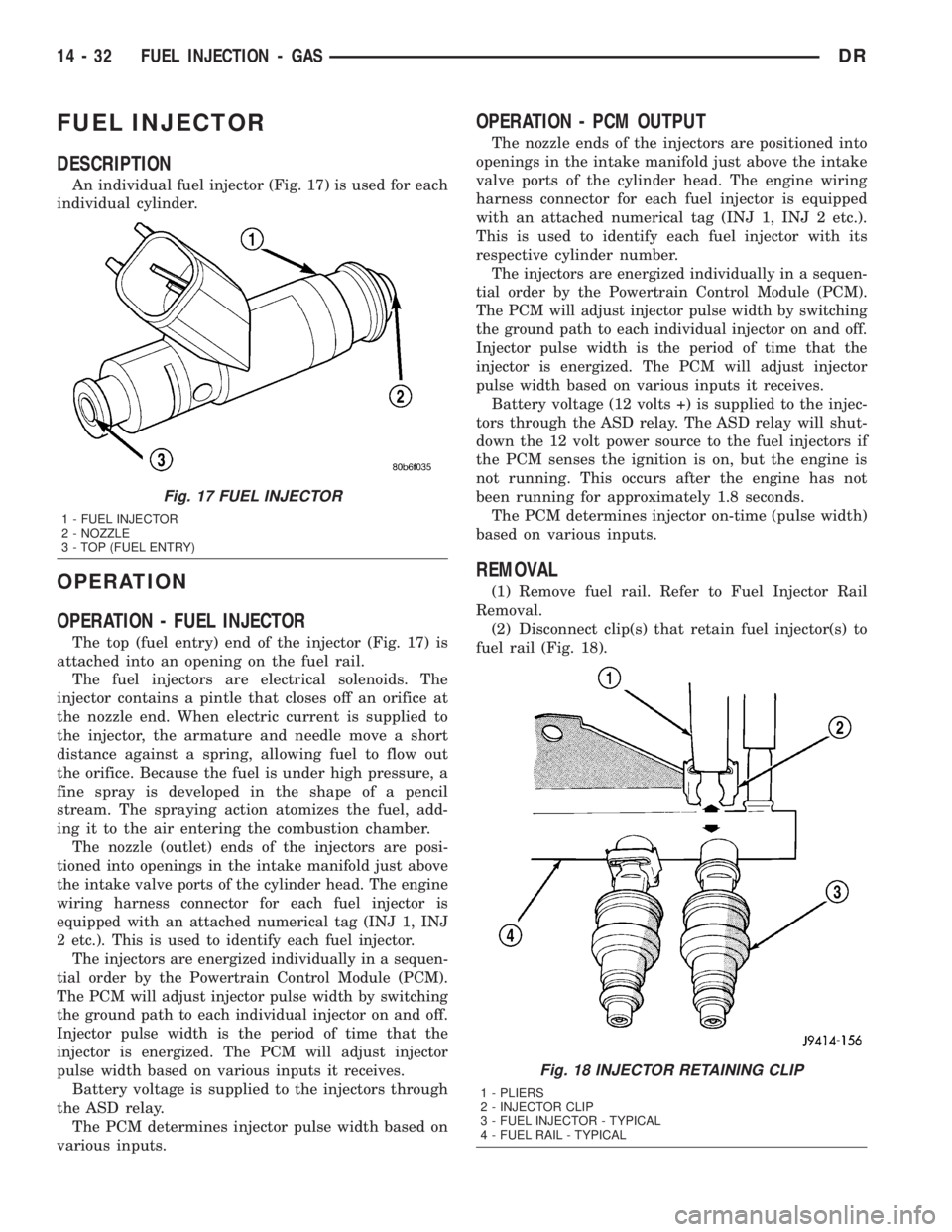
An individual fuel injector (Fig. 17) is used for each
individual cylinder.
OPERATION
OPERATION - FUEL INJECTOR
The top (fuel entry) end of the injector (Fig. 17) is
attached into an opening on the fuel rail.
The fuel injectors are electrical solenoids. The
injector contains a pintle that closes off an orifice at
the nozzle end. When electric current is supplied to
the injector, the armature and needle move a short
distance against a spring, allowing fuel to flow out
the orifice. Because the fuel is under high pressure, a
fine spray is developed in the shape of a pencil
stream. The spraying action atomizes the fuel, add-
ing it to the air entering the combustion chamber.
The nozzle (outlet) ends of the injectors are posi-
tioned into openings in the intake manifold just above
the intake valve ports of the cylinder head. The engine
wiring harness connector for each fuel injector is
equipped with an attached numerical tag (INJ 1, INJ
2 etc.). This is used to identify each fuel injector.
The injectors are energized individually in a sequen-
tial order by the Powertrain Control Module (PCM).
The PCM will adjust injector pulse width by switching
the ground path to each individual injector on and off.
Injector pulse width is the period of time that the
injector is energized. The PCM will adjust injector
pulse width based on various inputs it receives.
Battery voltage is supplied to the injectors through
the ASD relay.
The PCM determines injector pulse width based on
various inputs.
OPERATION - PCM OUTPUT
The nozzle ends of the injectors are positioned into
openings in the intake manifold just above the intake
valve ports of the cylinder head. The engine wiring
harness connector for each fuel injector is equipped
with an attached numerical tag (INJ 1, INJ 2 etc.).
This is used to identify each fuel injector with its
respective cylinder number.
The injectors are energized individually in a sequen-
tial order by the Powertrain Control Module (PCM).
The PCM will adjust injector pulse width by switching
the ground path to each individual injector on and off.
Injector pulse width is the period of time that the
injector is energized. The PCM will adjust injector
pulse width based on various inputs it receives.
Battery voltage (12 volts +) is supplied to the injec-
tors through the ASD relay. The ASD relay will shut-
down the 12 volt power source to the fuel injectors if
the PCM senses the ignition is on, but the engine is
not running. This occurs after the engine has not
been running for approximately 1.8 seconds.
The PCM determines injector on-time (pulse width)
based on various inputs.
REMOVAL
(1) Remove fuel rail. Refer to Fuel Injector Rail
Removal.
(2) Disconnect clip(s) that retain fuel injector(s) to
fuel rail (Fig. 18).
Fig. 17 FUEL INJECTOR
1 - FUEL INJECTOR
2 - NOZZLE
3 - TOP (FUEL ENTRY)
Fig. 18 INJECTOR RETAINING CLIP
1 - PLIERS
2 - INJECTOR CLIP
3 - FUEL INJECTOR - TYPICAL
4 - FUEL RAIL - TYPICAL
14 - 32 FUEL INJECTION - GASDR
Page 1730 of 2895
INSTALLATION
(1) Install fuel injector(s) into fuel rail assembly
and install retaining clip(s).
(2) If same injector(s) is being reinstalled, install
new o-ring(s).
(3) Apply a small amount of clean engine oil to
each injector o-ring. This will aid in installation.
(4) Install fuel rail. Refer to Fuel Rail Installation.
(5) Start engine and check for fuel leaks.
FUEL PUMP RELAY
DESCRIPTION
The 5±pin, 12±volt, fuel pump relay is located in
the Power Distribution Center (PDC). Refer to the
label on the PDC cover for relay location.
OPERATION
The Powertrain Control Module (PCM) energizes
the electric fuel pump through the fuel pump relay.
The fuel pump relay is energized by first applying
battery voltage to it when the ignition key is turned
ON, and then applying a ground signal to the relay
from the PCM.
Whenever the ignition key is turned ON, the elec-
tric fuel pump will operate. But, the PCM will shut-
down the ground circuit to the fuel pump relay in
approximately 1±3 seconds unless the engine is oper-
ating or the starter motor is engaged.
REMOVAL
The fuel pump relay is located in the Power Distri-
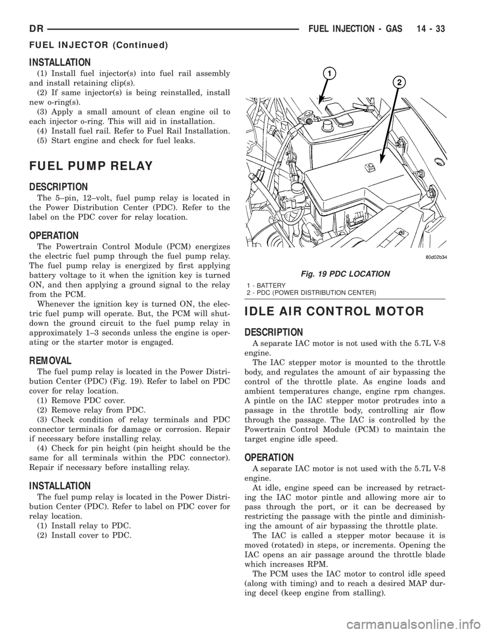
bution Center (PDC) (Fig. 19). Refer to label on PDC
cover for relay location.
(1) Remove PDC cover.
(2) Remove relay from PDC.
(3) Check condition of relay terminals and PDC
connector terminals for damage or corrosion. Repair
if necessary before installing relay.
(4) Check for pin height (pin height should be the
same for all terminals within the PDC connector).
Repair if necessary before installing relay.
INSTALLATION
The fuel pump relay is located in the Power Distri-
bution Center (PDC). Refer to label on PDC cover for
relay location.
(1) Install relay to PDC.
(2) Install cover to PDC.
IDLE AIR CONTROL MOTOR
DESCRIPTION
A separate IAC motor is not used with the 5.7L V-8
engine.
The IAC stepper motor is mounted to the throttle
body, and regulates the amount of air bypassing the
control of the throttle plate. As engine loads and
ambient temperatures change, engine rpm changes.
A pintle on the IAC stepper motor protrudes into a
passage in the throttle body, controlling air flow
through the passage. The IAC is controlled by the
Powertrain Control Module (PCM) to maintain the
target engine idle speed.
OPERATION
A separate IAC motor is not used with the 5.7L V-8
engine.
At idle, engine speed can be increased by retract-
ing the IAC motor pintle and allowing more air to
pass through the port, or it can be decreased by
restricting the passage with the pintle and diminish-
ing the amount of air bypassing the throttle plate.
The IAC is called a stepper motor because it is
moved (rotated) in steps, or increments. Opening the
IAC opens an air passage around the throttle blade
which increases RPM.
The PCM uses the IAC motor to control idle speed
(along with timing) and to reach a desired MAP dur-
ing decel (keep engine from stalling).
Fig. 19 PDC LOCATION
1 - BATTERY
2 - PDC (POWER DISTRIBUTION CENTER)
DRFUEL INJECTION - GAS 14 - 33
FUEL INJECTOR (Continued)