DODGE RAM 2003 Service Repair Manual
Manufacturer: DODGE, Model Year: 2003, Model line: RAM, Model: DODGE RAM 2003Pages: 2895, PDF Size: 83.15 MB
Page 1931 of 2895
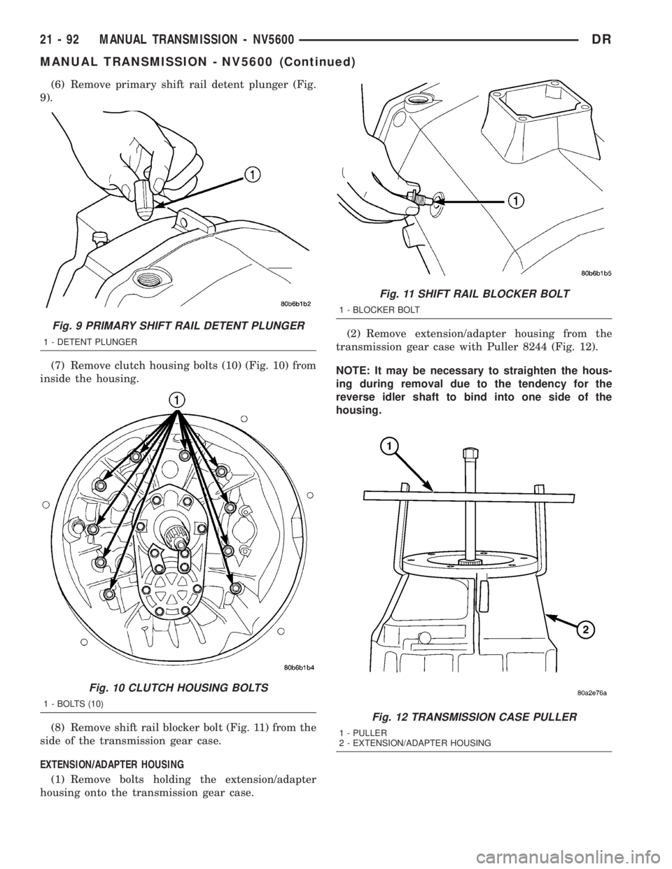
(6) Remove primary shift rail detent plunger (Fig.
9).
(7) Remove clutch housing bolts (10) (Fig. 10) from
inside the housing.
(8) Remove shift rail blocker bolt (Fig. 11) from the
side of the transmission gear case.
EXTENSION/ADAPTER HOUSING
(1) Remove bolts holding the extension/adapter
housing onto the transmission gear case.(2) Remove extension/adapter housing from the
transmission gear case with Puller 8244 (Fig. 12).
NOTE: It may be necessary to straighten the hous-
ing during removal due to the tendency for the
reverse idler shaft to bind into one side of the
housing.
Fig. 9 PRIMARY SHIFT RAIL DETENT PLUNGER
1 - DETENT PLUNGER
Fig. 10 CLUTCH HOUSING BOLTS
1 - BOLTS (10)
Fig. 11 SHIFT RAIL BLOCKER BOLT
1 - BLOCKER BOLT
Fig. 12 TRANSMISSION CASE PULLER
1 - PULLER
2 - EXTENSION/ADAPTER HOUSING
21 - 92 MANUAL TRANSMISSION - NV5600DR
MANUAL TRANSMISSION - NV5600 (Continued)
Page 1932 of 2895
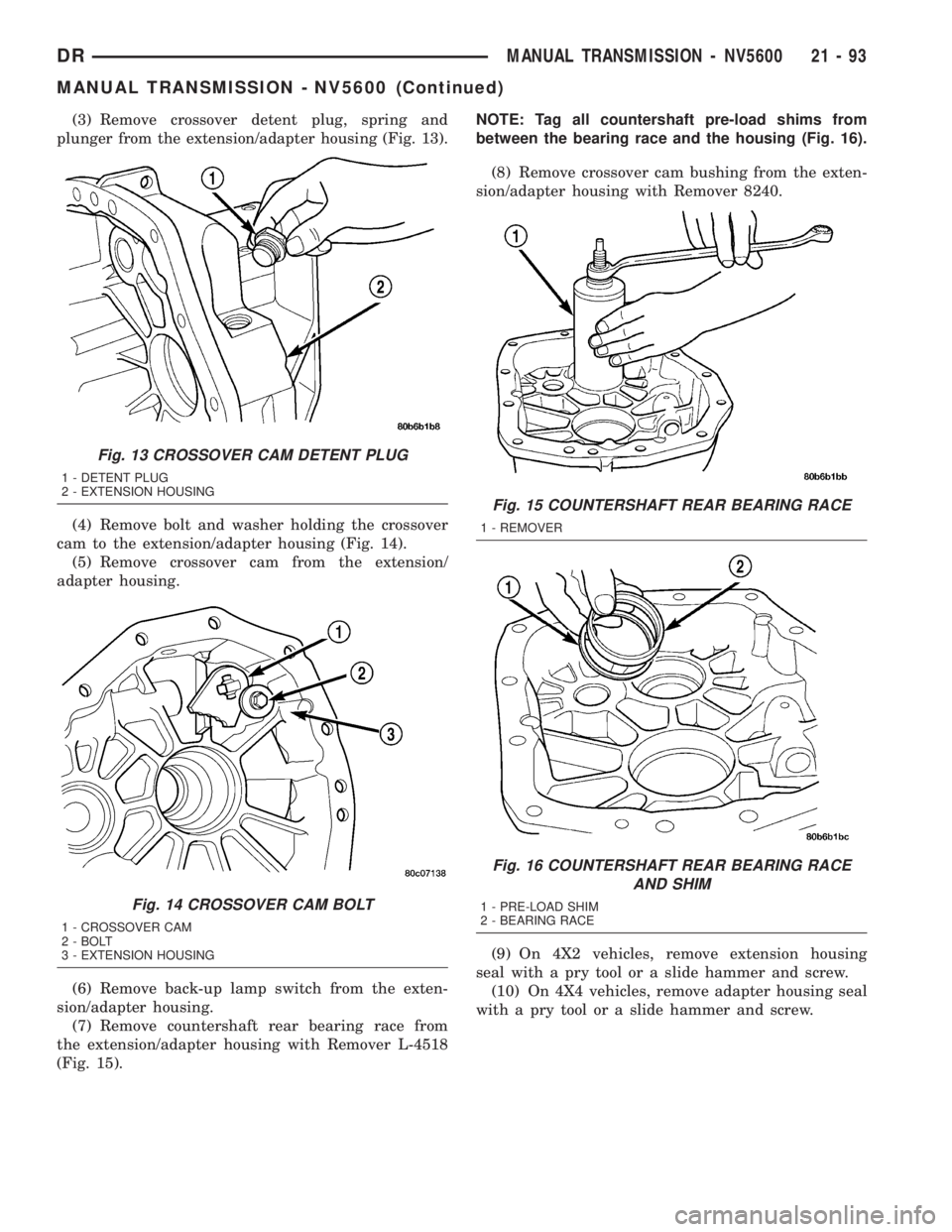
(3) Remove crossover detent plug, spring and
plunger from the extension/adapter housing (Fig. 13).
(4) Remove bolt and washer holding the crossover
cam to the extension/adapter housing (Fig. 14).
(5) Remove crossover cam from the extension/
adapter housing.
(6) Remove back-up lamp switch from the exten-
sion/adapter housing.
(7) Remove countershaft rear bearing race from
the extension/adapter housing with Remover L-4518
(Fig. 15).NOTE: Tag all countershaft pre-load shims from
between the bearing race and the housing (Fig. 16).
(8) Remove crossover cam bushing from the exten-
sion/adapter housing with Remover 8240.
(9) On 4X2 vehicles, remove extension housing
seal with a pry tool or a slide hammer and screw.
(10) On 4X4 vehicles, remove adapter housing seal
with a pry tool or a slide hammer and screw.
Fig. 13 CROSSOVER CAM DETENT PLUG
1 - DETENT PLUG
2 - EXTENSION HOUSING
Fig. 14 CROSSOVER CAM BOLT
1 - CROSSOVER CAM
2 - BOLT
3 - EXTENSION HOUSING
Fig. 15 COUNTERSHAFT REAR BEARING RACE
1 - REMOVER
Fig. 16 COUNTERSHAFT REAR BEARING RACE
AND SHIM
1 - PRE-LOAD SHIM
2 - BEARING RACE
DRMANUAL TRANSMISSION - NV5600 21 - 93
MANUAL TRANSMISSION - NV5600 (Continued)
Page 1933 of 2895
REVERSE GEAR
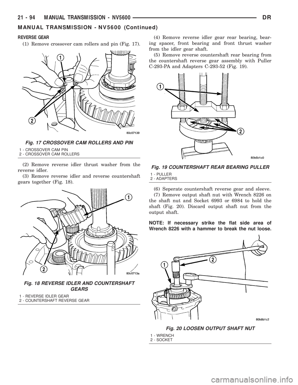
(1) Remove crossover cam rollers and pin (Fig. 17).
(2) Remove reverse idler thrust washer from the
reverse idler.
(3) Remove reverse idler and reverse countershaft
gears together (Fig. 18).(4) Remove reverse idler gear rear bearing, bear-
ing spacer, front bearing and front thrust washer
from the idler gear shaft.
(5) Remove reverse countershaft rear bearing from
the countershaft reverse gear assembly with Puller
C-293-PA and Adapters C-293-52 (Fig. 19).
(6) Seperate countershaft reverse gear and sleeve.
(7) Remove output shaft nut with Wrench 8226 on
the shaft nut and Socket 6993 or 6984 to hold the
shaft (Fig. 20). Discard output shaft nut from the
output shaft.
NOTE: If necessary strike the flat side area of
Wrench 8226 with a hammer to break the nut loose.
Fig. 17 CROSSOVER CAM ROLLERS AND PIN
1 - CROSSOVER CAM PIN
2 - CROSSOVER CAM ROLLERS
Fig. 18 REVERSE IDLER AND COUNTERSHAFT
GEARS
1 - REVERSE IDLER GEAR
2 - COUNTERSHAFT REVERSE GEAR
Fig. 19 COUNTERSHAFT REAR BEARING PULLER
1 - PULLER
2 - ADAPTERS
Fig. 20 LOOSEN OUTPUT SHAFT NUT
1 - WRENCH
2 - SOCKET
21 - 94 MANUAL TRANSMISSION - NV5600DR
MANUAL TRANSMISSION - NV5600 (Continued)
Page 1934 of 2895
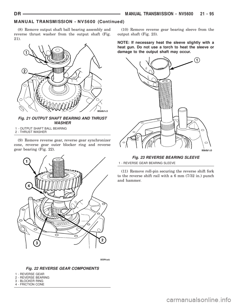
(8) Remove output shaft ball bearing assembly and
reverse thrust washer from the output shaft (Fig.
21).
(9) Remove reverse gear, reverse gear synchronizer
cone, reverse gear outer blocker ring and reverse
gear bearing (Fig. 22).(10) Remove reverse gear bearing sleeve from the
output shaft (Fig. 23).
NOTE: If necessary heat the sleeve slightly with a
heat gun. Do not use a torch to heat the sleeve or
damage to the output shaft may occur.
(11) Remove roll-pin securing the reverse shift fork
to the reverse shift rail witha6mm(7/32 in.) punch
and hammer.
Fig. 21 OUTPUT SHAFT BEARING AND THRUST
WASHER
1 - OUTPUT SHAFT BALL BEARING
2 - THRUST WASHER
Fig. 22 REVERSE GEAR COMPONENTS
1 - REVERSE GEAR
2 - REVERSE BEARING
3 - BLOCKER RING
4 - FRICTION CONE
Fig. 23 REVERSE BEARING SLEEVE
1 - REVERSE GEAR BEARING SLEEVE
DRMANUAL TRANSMISSION - NV5600 21 - 95
MANUAL TRANSMISSION - NV5600 (Continued)
Page 1935 of 2895
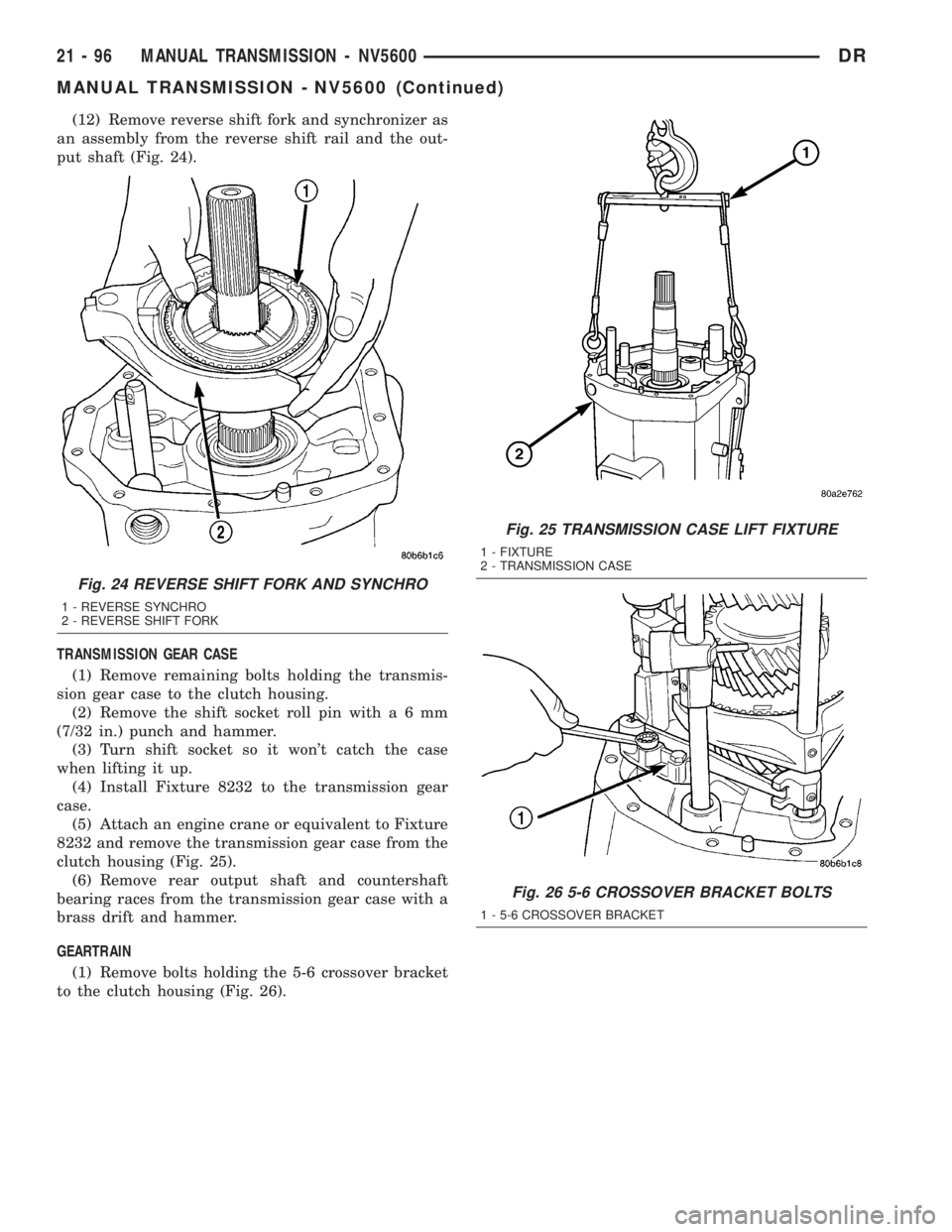
(12) Remove reverse shift fork and synchronizer as
an assembly from the reverse shift rail and the out-
put shaft (Fig. 24).
TRANSMISSION GEAR CASE
(1) Remove remaining bolts holding the transmis-
sion gear case to the clutch housing.
(2) Remove the shift socket roll pin witha6mm
(7/32 in.) punch and hammer.
(3) Turn shift socket so it won't catch the case
when lifting it up.
(4) Install Fixture 8232 to the transmission gear
case.
(5) Attach an engine crane or equivalent to Fixture
8232 and remove the transmission gear case from the
clutch housing (Fig. 25).
(6) Remove rear output shaft and countershaft
bearing races from the transmission gear case with a
brass drift and hammer.
GEARTRAIN
(1) Remove bolts holding the 5-6 crossover bracket
to the clutch housing (Fig. 26).
Fig. 24 REVERSE SHIFT FORK AND SYNCHRO
1 - REVERSE SYNCHRO
2 - REVERSE SHIFT FORK
Fig. 25 TRANSMISSION CASE LIFT FIXTURE
1 - FIXTURE
2 - TRANSMISSION CASE
Fig. 26 5-6 CROSSOVER BRACKET BOLTS
1 - 5-6 CROSSOVER BRACKET
21 - 96 MANUAL TRANSMISSION - NV5600DR
MANUAL TRANSMISSION - NV5600 (Continued)
Page 1936 of 2895
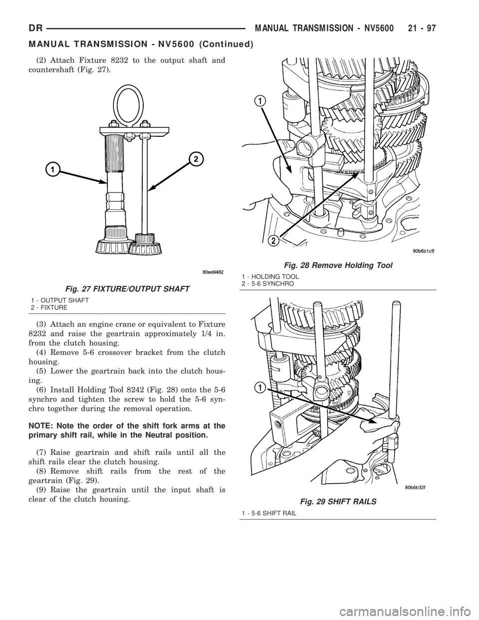
(2) Attach Fixture 8232 to the output shaft and
countershaft (Fig. 27).
(3) Attach an engine crane or equivalent to Fixture
8232 and raise the geartrain approximately 1/4 in.
from the clutch housing.
(4) Remove 5-6 crossover bracket from the clutch
housing.
(5) Lower the geartrain back into the clutch hous-
ing.
(6) Install Holding Tool 8242 (Fig. 28) onto the 5-6
synchro and tighten the screw to hold the 5-6 syn-
chro together during the removal operation.
NOTE: Note the order of the shift fork arms at the
primary shift rail, while in the Neutral position.
(7) Raise geartrain and shift rails until all the
shift rails clear the clutch housing.
(8) Remove shift rails from the rest of the
geartrain (Fig. 29).
(9) Raise the geartrain until the input shaft is
clear of the clutch housing.
Fig. 27 FIXTURE/OUTPUT SHAFT
1 - OUTPUT SHAFT
2 - FIXTURE
Fig. 28 Remove Holding Tool
1 - HOLDING TOOL
2 - 5-6 SYNCHRO
Fig. 29 SHIFT RAILS
1 - 5-6 SHIFT RAIL
DRMANUAL TRANSMISSION - NV5600 21 - 97
MANUAL TRANSMISSION - NV5600 (Continued)
Page 1937 of 2895
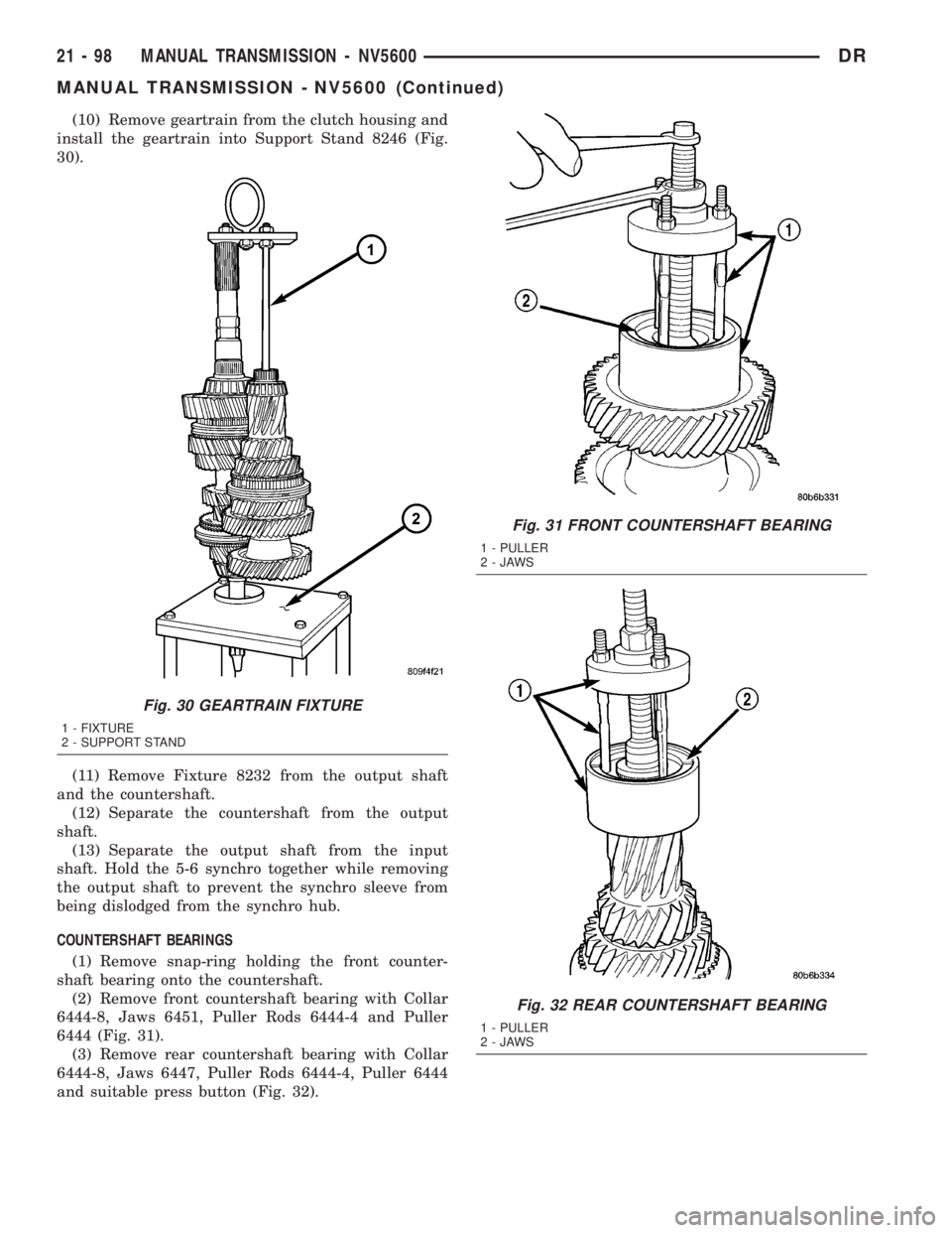
(10) Remove geartrain from the clutch housing and
install the geartrain into Support Stand 8246 (Fig.
30).
(11) Remove Fixture 8232 from the output shaft
and the countershaft.
(12) Separate the countershaft from the output
shaft.
(13) Separate the output shaft from the input
shaft. Hold the 5-6 synchro together while removing
the output shaft to prevent the synchro sleeve from
being dislodged from the synchro hub.
COUNTERSHAFT BEARINGS
(1) Remove snap-ring holding the front counter-
shaft bearing onto the countershaft.
(2) Remove front countershaft bearing with Collar
6444-8, Jaws 6451, Puller Rods 6444-4 and Puller
6444 (Fig. 31).
(3) Remove rear countershaft bearing with Collar
6444-8, Jaws 6447, Puller Rods 6444-4, Puller 6444
and suitable press button (Fig. 32).
Fig. 30 GEARTRAIN FIXTURE
1 - FIXTURE
2 - SUPPORT STAND
Fig. 31 FRONT COUNTERSHAFT BEARING
1 - PULLER
2-JAWS
Fig. 32 REAR COUNTERSHAFT BEARING
1 - PULLER
2-JAWS
21 - 98 MANUAL TRANSMISSION - NV5600DR
MANUAL TRANSMISSION - NV5600 (Continued)
Page 1938 of 2895
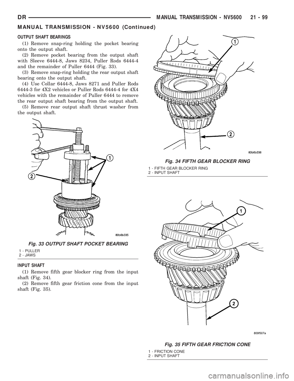
OUTPUT SHAFT BEARINGS
(1) Remove snap-ring holding the pocket bearing
onto the output shaft.
(2) Remove pocket bearing from the output shaft
with Sleeve 6444-8, Jaws 8234, Puller Rods 6444-4
and the remainder of Puller 6444 (Fig. 33).
(3) Remove snap-ring holding the rear output shaft
bearing onto the output shaft.
(4) Use Collar 6444-8, Jaws 8271 and Puller Rods
6444-3 for 4X2 vehicles or Puller Rods 6444-4 for 4X4
vehicles with the remainder of Puller 6444 to remove
the rear output shaft bearing from the output shaft.
(5) Remove rear output shaft thrust washer from
the output shaft.
INPUT SHAFT
(1) Remove fifth gear blocker ring from the input
shaft (Fig. 34).
(2) Remove fifth gear friction cone from the input
shaft (Fig. 35).
Fig. 33 OUTPUT SHAFT POCKET BEARING
1 - PULLER
2-JAWS
Fig. 34 FIFTH GEAR BLOCKER RING
1 - FIFTH GEAR BLOCKER RING
2 - INPUT SHAFT
Fig. 35 FIFTH GEAR FRICTION CONE
1 - FRICTION CONE
2 - INPUT SHAFT
DRMANUAL TRANSMISSION - NV5600 21 - 99
MANUAL TRANSMISSION - NV5600 (Continued)
Page 1939 of 2895
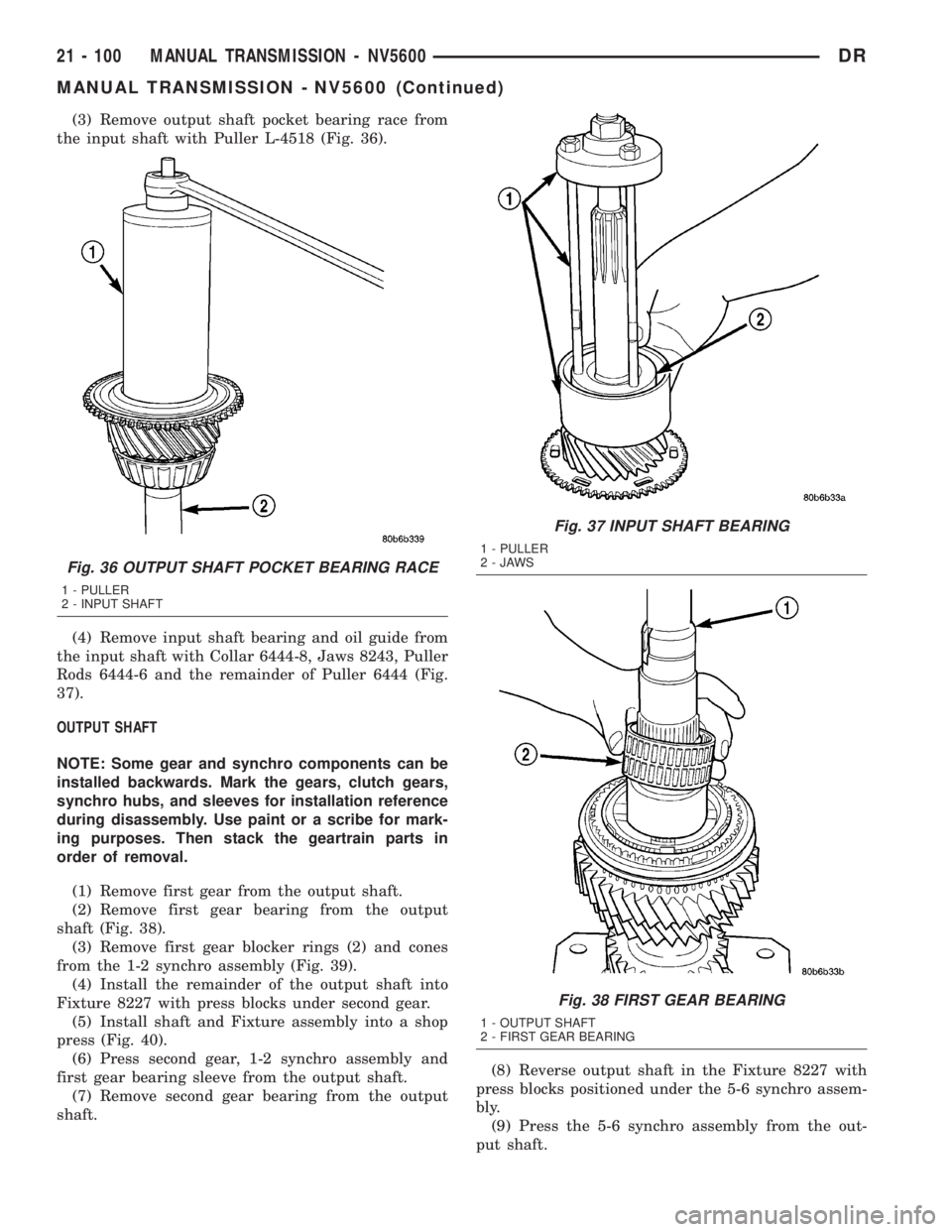
(3) Remove output shaft pocket bearing race from
the input shaft with Puller L-4518 (Fig. 36).
(4) Remove input shaft bearing and oil guide from
the input shaft with Collar 6444-8, Jaws 8243, Puller
Rods 6444-6 and the remainder of Puller 6444 (Fig.
37).
OUTPUT SHAFT
NOTE: Some gear and synchro components can be
installed backwards. Mark the gears, clutch gears,
synchro hubs, and sleeves for installation reference
during disassembly. Use paint or a scribe for mark-
ing purposes. Then stack the geartrain parts in
order of removal.
(1) Remove first gear from the output shaft.
(2) Remove first gear bearing from the output
shaft (Fig. 38).
(3) Remove first gear blocker rings (2) and cones
from the 1-2 synchro assembly (Fig. 39).
(4) Install the remainder of the output shaft into
Fixture 8227 with press blocks under second gear.
(5) Install shaft and Fixture assembly into a shop
press (Fig. 40).
(6) Press second gear, 1-2 synchro assembly and
first gear bearing sleeve from the output shaft.
(7) Remove second gear bearing from the output
shaft.(8) Reverse output shaft in the Fixture 8227 with
press blocks positioned under the 5-6 synchro assem-
bly.
(9) Press the 5-6 synchro assembly from the out-
put shaft.
Fig. 36 OUTPUT SHAFT POCKET BEARING RACE
1 - PULLER
2 - INPUT SHAFT
Fig. 37 INPUT SHAFT BEARING
1 - PULLER
2-JAWS
Fig. 38 FIRST GEAR BEARING
1 - OUTPUT SHAFT
2 - FIRST GEAR BEARING
21 - 100 MANUAL TRANSMISSION - NV5600DR
MANUAL TRANSMISSION - NV5600 (Continued)
Page 1940 of 2895
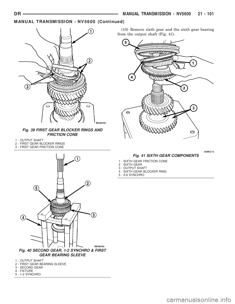
(10) Remove sixth gear and the sixth gear bearing
from the output shaft (Fig. 41).
Fig. 39 FIRST GEAR BLOCKER RINGS AND
FRICTION CONE
1 - OUTPUT SHAFT
2 - FIRST GEAR BLOCKER RINGS
3 - FIRST GEAR FRICTION CONE
Fig. 40 SECOND GEAR, 1-2 SYNCHRO & FIRST
GEAR BEARING SLEEVE
1 - OUTPUT SHAFT
2 - FIRST GEAR BEARING SLEEVE
3 - SECOND GEAR
4 - FIXTURE
5 - 1-2 SYNCHRO
Fig. 41 SIXTH GEAR COMPONENTS
1 - SIXTH GEAR FRICTION CONE
2 - SIXTH GEAR
3 - OUTPUT SHAFT
4 - SIXTH GEAR BLOCKER RING
5 - 5-6 SYNCHRO
DRMANUAL TRANSMISSION - NV5600 21 - 101
MANUAL TRANSMISSION - NV5600 (Continued)