DODGE RAM 2003 Service Repair Manual
Manufacturer: DODGE, Model Year: 2003, Model line: RAM, Model: DODGE RAM 2003Pages: 2895, PDF Size: 83.15 MB
Page 2301 of 2895
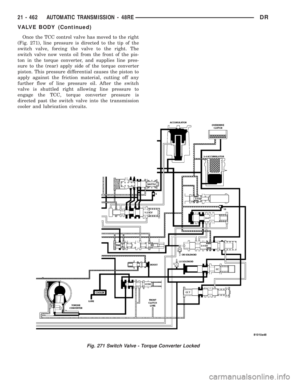
Once the TCC control valve has moved to the right
(Fig. 271), line pressure is directed to the tip of the
switch valve, forcing the valve to the right. The
switch valve now vents oil from the front of the pis-
ton in the torque converter, and supplies line pres-
sure to the (rear) apply side of the torque converter
piston. This pressure differential causes the piston to
apply against the friction material, cutting off any
further flow of line pressure oil. After the switch
valve is shuttled right allowing line pressure to
engage the TCC, torque converter pressure is
directed past the switch valve into the transmission
cooler and lubrication circuits.
Fig. 271 Switch Valve - Torque Converter Locked
21 - 462 AUTOMATIC TRANSMISSION - 48REDR
VALVE BODY (Continued)
Page 2302 of 2895
MANUAL VALVE
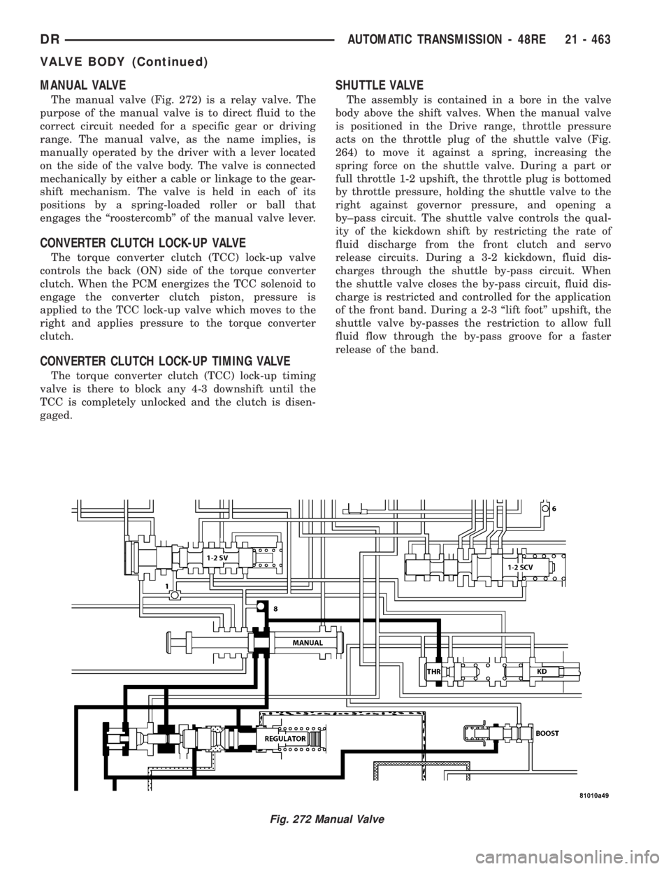
The manual valve (Fig. 272) is a relay valve. The
purpose of the manual valve is to direct fluid to the
correct circuit needed for a specific gear or driving
range. The manual valve, as the name implies, is
manually operated by the driver with a lever located
on the side of the valve body. The valve is connected
mechanically by either a cable or linkage to the gear-
shift mechanism. The valve is held in each of its
positions by a spring-loaded roller or ball that
engages the ªroostercombº of the manual valve lever.
CONVERTER CLUTCH LOCK-UP VALVE
The torque converter clutch (TCC) lock-up valve
controls the back (ON) side of the torque converter
clutch. When the PCM energizes the TCC solenoid to
engage the converter clutch piston, pressure is
applied to the TCC lock-up valve which moves to the
right and applies pressure to the torque converter
clutch.
CONVERTER CLUTCH LOCK-UP TIMING VALVE
The torque converter clutch (TCC) lock-up timing
valve is there to block any 4-3 downshift until the
TCC is completely unlocked and the clutch is disen-
gaged.
SHUTTLE VALVE
The assembly is contained in a bore in the valve
body above the shift valves. When the manual valve
is positioned in the Drive range, throttle pressure
acts on the throttle plug of the shuttle valve (Fig.
264) to move it against a spring, increasing the
spring force on the shuttle valve. During a part or
full throttle 1-2 upshift, the throttle plug is bottomed
by throttle pressure, holding the shuttle valve to the
right against governor pressure, and opening a
by±pass circuit. The shuttle valve controls the qual-
ity of the kickdown shift by restricting the rate of
fluid discharge from the front clutch and servo
release circuits. During a 3-2 kickdown, fluid dis-
charges through the shuttle by-pass circuit. When
the shuttle valve closes the by-pass circuit, fluid dis-
charge is restricted and controlled for the application
of the front band. During a 2-3 ªlift footº upshift, the
shuttle valve by-passes the restriction to allow full
fluid flow through the by-pass groove for a faster
release of the band.
Fig. 272 Manual Valve
DRAUTOMATIC TRANSMISSION - 48RE 21 - 463
VALVE BODY (Continued)
Page 2303 of 2895
BOOST VALVE
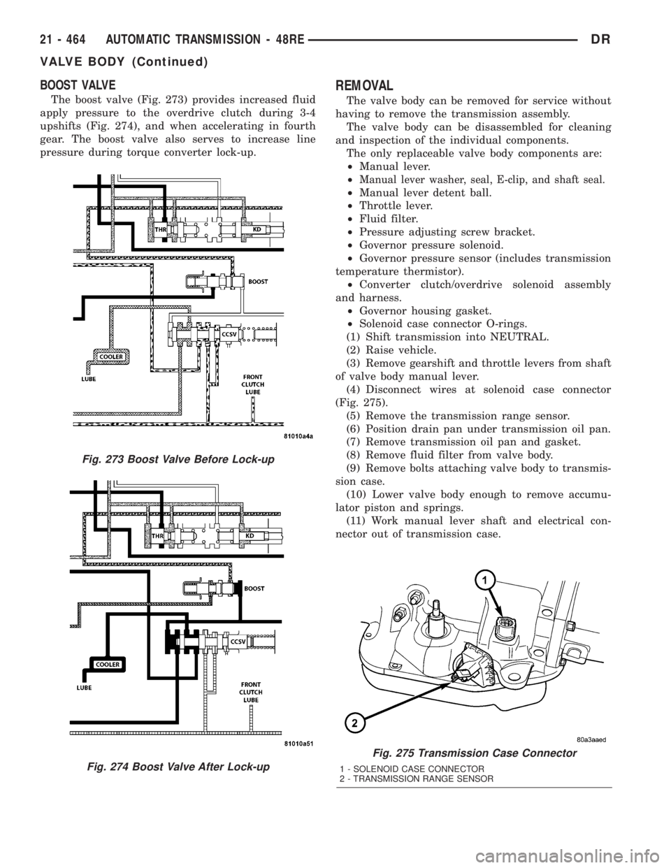
The boost valve (Fig. 273) provides increased fluid
apply pressure to the overdrive clutch during 3-4
upshifts (Fig. 274), and when accelerating in fourth
gear. The boost valve also serves to increase line
pressure during torque converter lock-up.
REMOVAL
The valve body can be removed for service without
having to remove the transmission assembly.
The valve body can be disassembled for cleaning
and inspection of the individual components.
The only replaceable valve body components are:
²Manual lever.
²
Manual lever washer, seal, E-clip, and shaft seal.
²Manual lever detent ball.
²Throttle lever.
²Fluid filter.
²Pressure adjusting screw bracket.
²Governor pressure solenoid.
²Governor pressure sensor (includes transmission
temperature thermistor).
²Converter clutch/overdrive solenoid assembly
and harness.
²Governor housing gasket.
²Solenoid case connector O-rings.
(1) Shift transmission into NEUTRAL.
(2) Raise vehicle.
(3) Remove gearshift and throttle levers from shaft
of valve body manual lever.
(4) Disconnect wires at solenoid case connector
(Fig. 275).
(5) Remove the transmission range sensor.
(6) Position drain pan under transmission oil pan.
(7) Remove transmission oil pan and gasket.
(8) Remove fluid filter from valve body.
(9) Remove bolts attaching valve body to transmis-
sion case.
(10) Lower valve body enough to remove accumu-
lator piston and springs.
(11) Work manual lever shaft and electrical con-
nector out of transmission case.
Fig. 275 Transmission Case Connector
1 - SOLENOID CASE CONNECTOR
2 - TRANSMISSION RANGE SENSOR
Fig. 273 Boost Valve Before Lock-up
Fig. 274 Boost Valve After Lock-up
21 - 464 AUTOMATIC TRANSMISSION - 48REDR
VALVE BODY (Continued)
Page 2304 of 2895
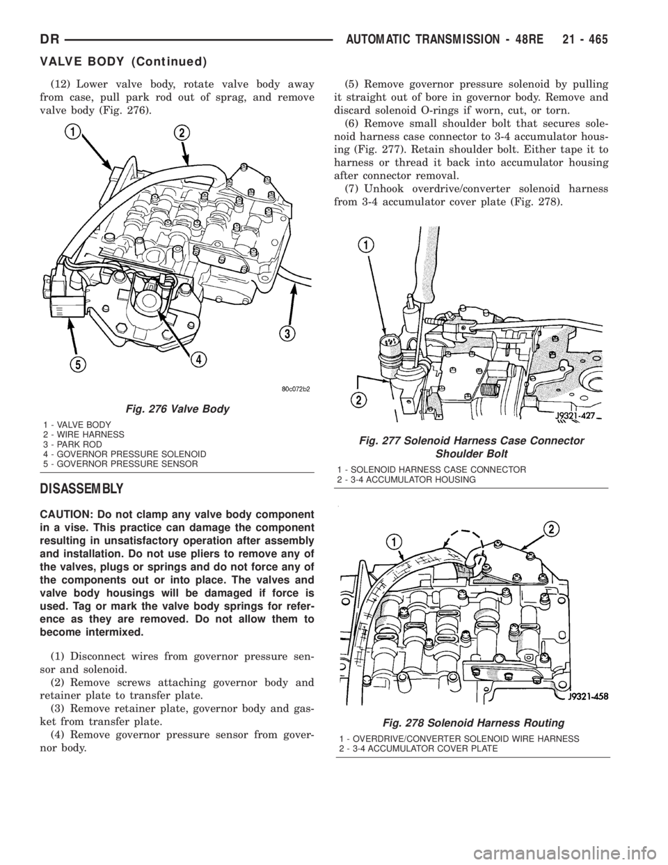
(12) Lower valve body, rotate valve body away
from case, pull park rod out of sprag, and remove
valve body (Fig. 276).
DISASSEMBLY
CAUTION: Do not clamp any valve body component
in a vise. This practice can damage the component
resulting in unsatisfactory operation after assembly
and installation. Do not use pliers to remove any of
the valves, plugs or springs and do not force any of
the components out or into place. The valves and
valve body housings will be damaged if force is
used. Tag or mark the valve body springs for refer-
ence as they are removed. Do not allow them to
become intermixed.
(1) Disconnect wires from governor pressure sen-
sor and solenoid.
(2) Remove screws attaching governor body and
retainer plate to transfer plate.
(3) Remove retainer plate, governor body and gas-
ket from transfer plate.
(4) Remove governor pressure sensor from gover-
nor body.(5) Remove governor pressure solenoid by pulling
it straight out of bore in governor body. Remove and
discard solenoid O-rings if worn, cut, or torn.
(6) Remove small shoulder bolt that secures sole-
noid harness case connector to 3-4 accumulator hous-
ing (Fig. 277). Retain shoulder bolt. Either tape it to
harness or thread it back into accumulator housing
after connector removal.
(7) Unhook overdrive/converter solenoid harness
from 3-4 accumulator cover plate (Fig. 278).
Fig. 277 Solenoid Harness Case Connector
Shoulder Bolt
1 - SOLENOID HARNESS CASE CONNECTOR
2 - 3-4 ACCUMULATOR HOUSING
Fig. 278 Solenoid Harness Routing
1 - OVERDRIVE/CONVERTER SOLENOID WIRE HARNESS
2 - 3-4 ACCUMULATOR COVER PLATE
Fig. 276 Valve Body
1 - VALVE BODY
2 - WIRE HARNESS
3 - PARK ROD
4 - GOVERNOR PRESSURE SOLENOID
5 - GOVERNOR PRESSURE SENSOR
DRAUTOMATIC TRANSMISSION - 48RE 21 - 465
VALVE BODY (Continued)
Page 2305 of 2895

(8) Turn valve body over and remove screws that
attach overdrive/converter solenoid assembly to valve
body (Fig. 279).
(9) Remove solenoid and harness assembly from
valve body (Fig. 280).
(10) Remove boost valve cover (Fig. 281).
(11) Remove boost valve retainer, valve spring and
boost valve (Fig. 282).
(12) Secure detent ball and spring with Retainer
Tool 6583 (Fig. 283).
Fig. 283 Detent Ball Spring
1 - SPECIAL TOOL 6583 POSITIONED ON DETENT HOUSING
Fig. 279 Solenoid Assembly Screws
1 - OVERDRIVE/CONVERTER CLUTCH SOLENOID ASSEMBLY
2 - HARNESS
Fig. 280 Solenoid Assembly
1 - GOVERNOR SOLENOID WIRES
2 - CONVERTER CLUTCH SOLENOID
3 - SOLENOID SCREWS
4 - GOVERNOR SENSOR WIRES
5 - OVERDRIVE SOLENOID
6 - HARNESS
7 - CASE CONNECTOR
Fig. 281 Boost Valve Cover Location
1 - BOOST VALVE HOUSING AND COVER
2 - BOOST VALVE TUBE
Fig. 282 Boost Valve Components
1 - SPRING AND VALVE RETAINER
2 - COVER SCREWS
3 - BOOST VALVE COVER
4 - BOOST VALVE PLUG
5 - BOOST VALVE
6 - BOOST VALVE SPRING
21 - 466 AUTOMATIC TRANSMISSION - 48REDR
VALVE BODY (Continued)
Page 2306 of 2895
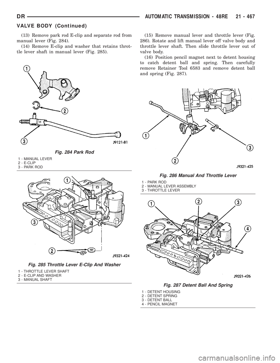
(13) Remove park rod E-clip and separate rod from
manual lever (Fig. 284).
(14) Remove E-clip and washer that retains throt-
tle lever shaft in manual lever (Fig. 285).(15) Remove manual lever and throttle lever (Fig.
286). Rotate and lift manual lever off valve body and
throttle lever shaft. Then slide throttle lever out of
valve body.
(16) Position pencil magnet next to detent housing
to catch detent ball and spring. Then carefully
remove Retainer Tool 6583 and remove detent ball
and spring (Fig. 287).
Fig. 284 Park Rod
1 - MANUAL LEVER
2 - E-CLIP
3 - PARK ROD
Fig. 285 Throttle Lever E-Clip And Washer
1 - THROTTLE LEVER SHAFT
2 - E-CLIP AND WASHER
3 - MANUAL SHAFT
Fig. 286 Manual And Throttle Lever
1 - PARK ROD
2 - MANUAL LEVER ASSEMBLY
3 - THROTTLE LEVER
Fig. 287 Detent Ball And Spring
1 - DETENT HOUSING
2 - DETENT SPRING
3 - DETENT BALL
4 - PENCIL MAGNET
DRAUTOMATIC TRANSMISSION - 48RE 21 - 467
VALVE BODY (Continued)
Page 2307 of 2895
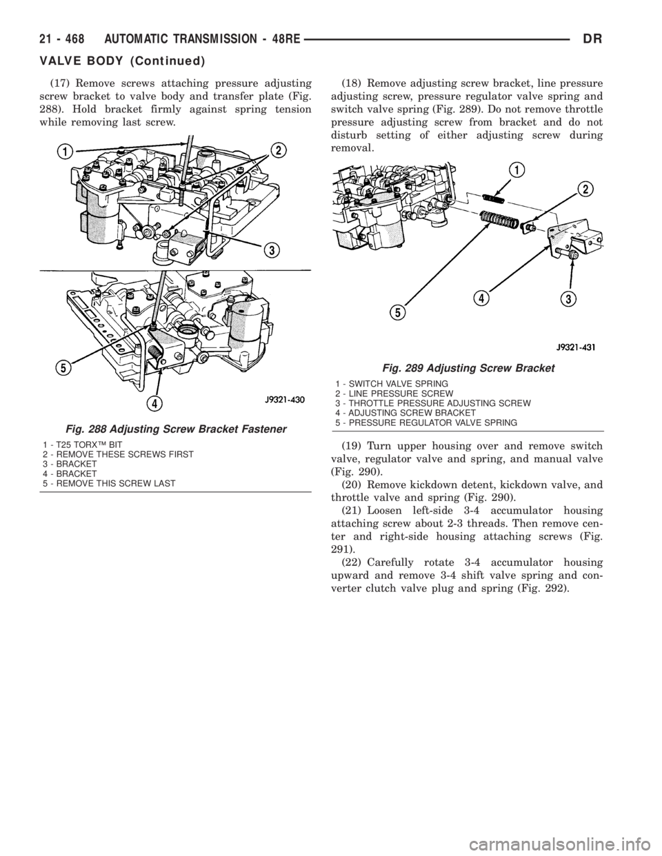
(17) Remove screws attaching pressure adjusting
screw bracket to valve body and transfer plate (Fig.
288). Hold bracket firmly against spring tension
while removing last screw.(18) Remove adjusting screw bracket, line pressure
adjusting screw, pressure regulator valve spring and
switch valve spring (Fig. 289). Do not remove throttle
pressure adjusting screw from bracket and do not
disturb setting of either adjusting screw during
removal.
(19) Turn upper housing over and remove switch
valve, regulator valve and spring, and manual valve
(Fig. 290).
(20) Remove kickdown detent, kickdown valve, and
throttle valve and spring (Fig. 290).
(21) Loosen left-side 3-4 accumulator housing
attaching screw about 2-3 threads. Then remove cen-
ter and right-side housing attaching screws (Fig.
291).
(22) Carefully rotate 3-4 accumulator housing
upward and remove 3-4 shift valve spring and con-
verter clutch valve plug and spring (Fig. 292).
Fig. 289 Adjusting Screw Bracket
1 - SWITCH VALVE SPRING
2 - LINE PRESSURE SCREW
3 - THROTTLE PRESSURE ADJUSTING SCREW
4 - ADJUSTING SCREW BRACKET
5 - PRESSURE REGULATOR VALVE SPRING
Fig. 288 Adjusting Screw Bracket Fastener
1 - T25 TORXŸ BIT
2 - REMOVE THESE SCREWS FIRST
3 - BRACKET
4 - BRACKET
5 - REMOVE THIS SCREW LAST
21 - 468 AUTOMATIC TRANSMISSION - 48REDR
VALVE BODY (Continued)
Page 2308 of 2895
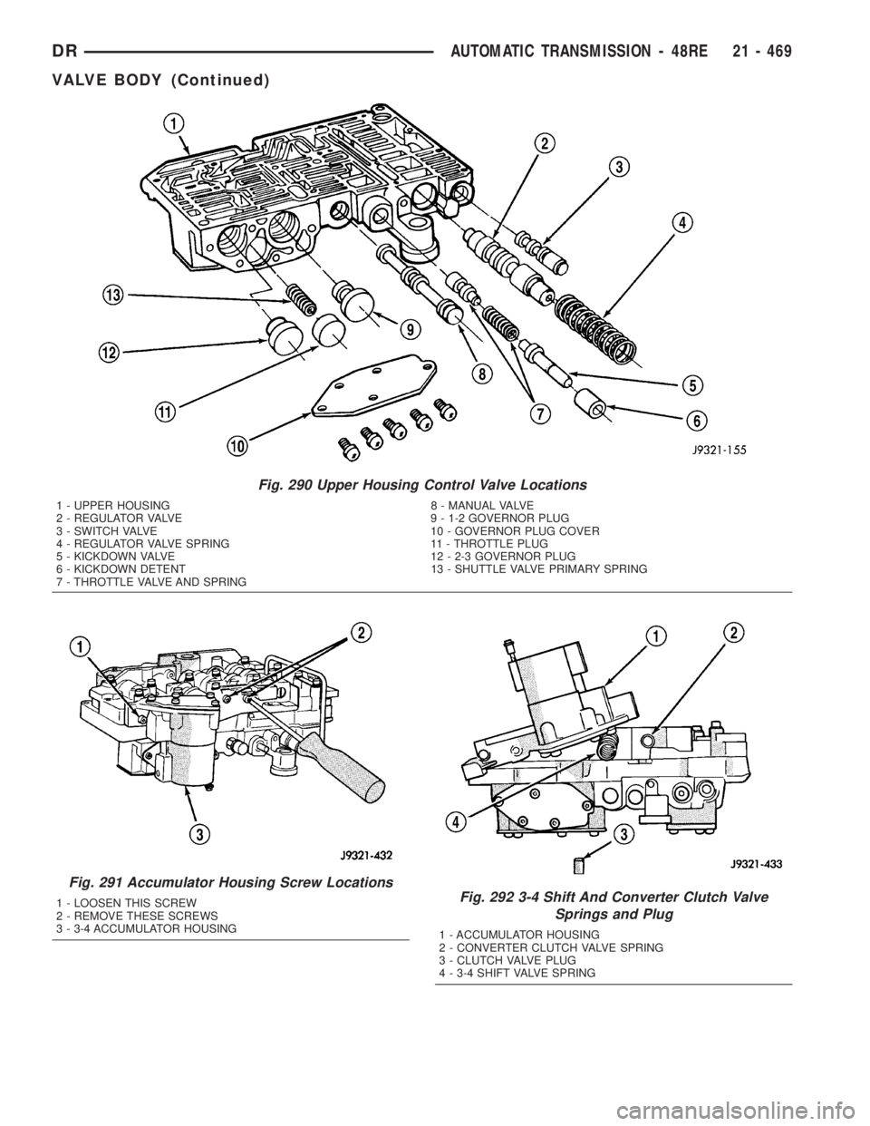
Fig. 290 Upper Housing Control Valve Locations
1 - UPPER HOUSING 8 - MANUAL VALVE
2 - REGULATOR VALVE 9 - 1-2 GOVERNOR PLUG
3 - SWITCH VALVE 10 - GOVERNOR PLUG COVER
4 - REGULATOR VALVE SPRING 11 - THROTTLE PLUG
5 - KICKDOWN VALVE 12 - 2-3 GOVERNOR PLUG
6 - KICKDOWN DETENT 13 - SHUTTLE VALVE PRIMARY SPRING
7 - THROTTLE VALVE AND SPRING
Fig. 291 Accumulator Housing Screw Locations
1 - LOOSEN THIS SCREW
2 - REMOVE THESE SCREWS
3 - 3-4 ACCUMULATOR HOUSINGFig. 292 3-4 Shift And Converter Clutch Valve
Springs and Plug
1 - ACCUMULATOR HOUSING
2 - CONVERTER CLUTCH VALVE SPRING
3 - CLUTCH VALVE PLUG
4 - 3-4 SHIFT VALVE SPRING
DRAUTOMATIC TRANSMISSION - 48RE 21 - 469
VALVE BODY (Continued)
Page 2309 of 2895
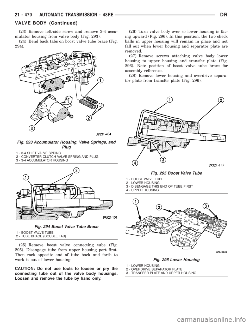
(23) Remove left-side screw and remove 3-4 accu-
mulator housing from valve body (Fig. 293).
(24) Bend back tabs on boost valve tube brace (Fig.
294).
(25) Remove boost valve connecting tube (Fig.
295). Disengage tube from upper housing port first.
Then rock opposite end of tube back and forth to
work it out of lower housing.
CAUTION: Do not use tools to loosen or pry the
connecting tube out of the valve body housings.
Loosen and remove the tube by hand only.(26) Turn valve body over so lower housing is fac-
ing upward (Fig. 296). In this position, the two check
balls in upper housing will remain in place and not
fall out when lower housing and separator plate are
removed.
(27) Remove screws attaching valve body lower
housing to upper housing and transfer plate (Fig.
296). Note position of boost valve tube brace for
assembly reference.
(28) Remove lower housing and overdrive separa-
tor plate from transfer plate (Fig. 296).
Fig. 295 Boost Valve Tube
1 - BOOST VALVE TUBE
2 - LOWER HOUSING
3 - DISENGAGE THIS END OF TUBE FIRST
4 - UPPER HOUSING
Fig. 296 Lower Housing
1 - LOWER HOUSING
2 - OVERDRIVE SEPARATOR PLATE
3 - TRANSFER PLATE AND UPPER HOUSING
Fig. 293 Accumulator Housing, Valve Springs, and
Plug
1 - 3-4 SHIFT VALVE SPRING
2 - CONVERTER CLUTCH VALVE SPRING AND PLUG
3 - 3-4 ACCUMULATOR HOUSING
Fig. 294 Boost Valve Tube Brace
1 - BOOST VALVE TUBE
2 - TUBE BRACE (DOUBLE TAB)
21 - 470 AUTOMATIC TRANSMISSION - 48REDR
VALVE BODY (Continued)
Page 2310 of 2895
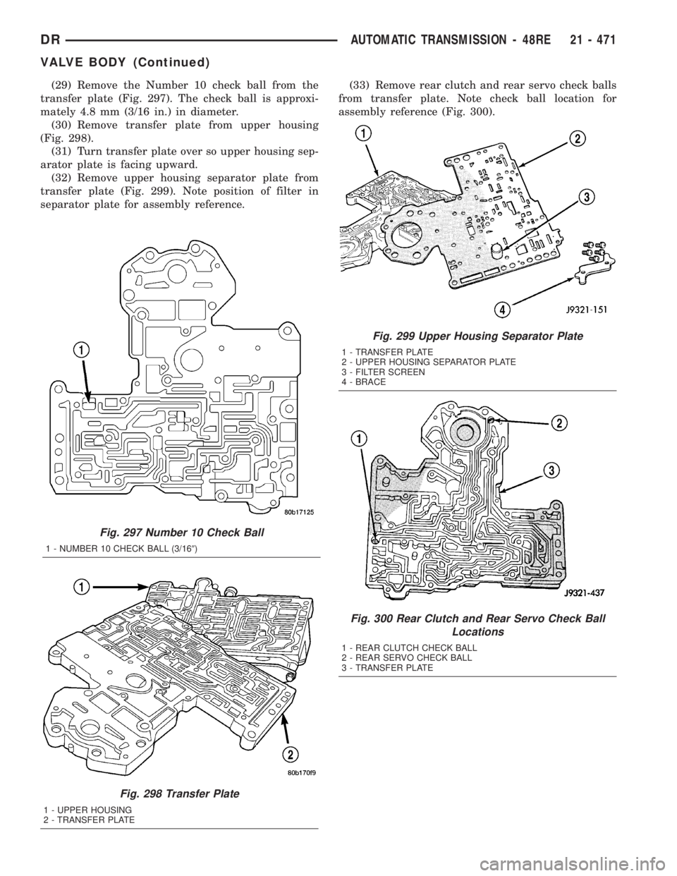
(29) Remove the Number 10 check ball from the
transfer plate (Fig. 297). The check ball is approxi-
mately 4.8 mm (3/16 in.) in diameter.
(30) Remove transfer plate from upper housing
(Fig. 298).
(31) Turn transfer plate over so upper housing sep-
arator plate is facing upward.
(32) Remove upper housing separator plate from
transfer plate (Fig. 299). Note position of filter in
separator plate for assembly reference.(33) Remove rear clutch and rear servo check balls
from transfer plate. Note check ball location for
assembly reference (Fig. 300).
Fig. 297 Number 10 Check Ball
1 - NUMBER 10 CHECK BALL (3/169)
Fig. 298 Transfer Plate
1 - UPPER HOUSING
2 - TRANSFER PLATE
Fig. 299 Upper Housing Separator Plate
1 - TRANSFER PLATE
2 - UPPER HOUSING SEPARATOR PLATE
3 - FILTER SCREEN
4 - BRACE
Fig. 300 Rear Clutch and Rear Servo Check Ball
Locations
1 - REAR CLUTCH CHECK BALL
2 - REAR SERVO CHECK BALL
3 - TRANSFER PLATE
DRAUTOMATIC TRANSMISSION - 48RE 21 - 471
VALVE BODY (Continued)