sensor DODGE RAM 2003 Service Repair Manual
[x] Cancel search | Manufacturer: DODGE, Model Year: 2003, Model line: RAM, Model: DODGE RAM 2003Pages: 2895, PDF Size: 83.15 MB
Page 44 of 2895
LARGE BUSHING
NOTE: Extreme pressure lubrication must be used
on the threaded portions of the tool. This will
increase the longevity of the tool and insure proper
operation during the removal and installation pro-
cess.
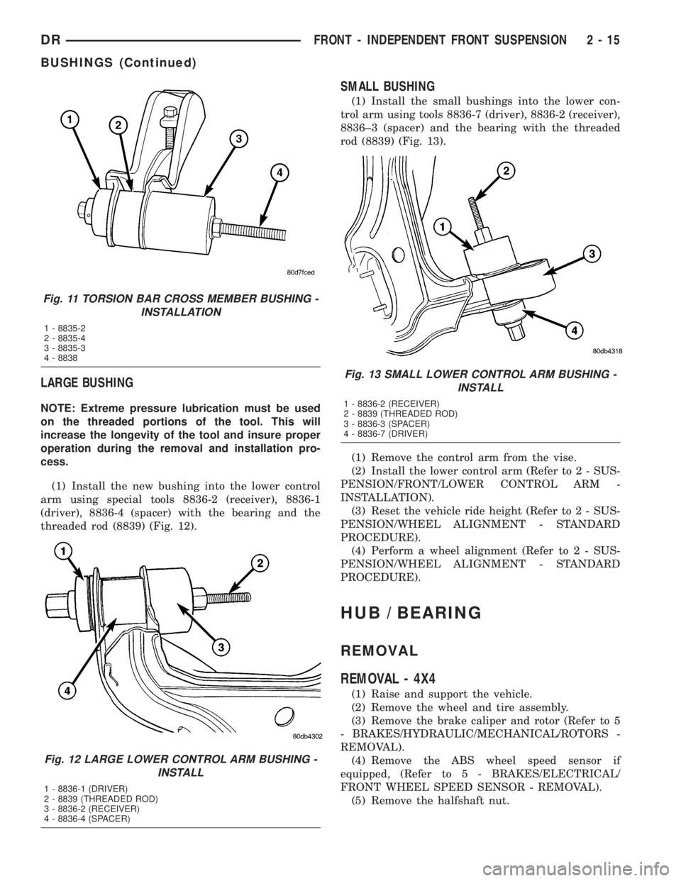
(1) Install the new bushing into the lower control
arm using special tools 8836-2 (receiver), 8836-1
(driver), 8836-4 (spacer) with the bearing and the
threaded rod (8839) (Fig. 12).
SMALL BUSHING
(1) Install the small bushings into the lower con-
trol arm using tools 8836-7 (driver), 8836-2 (receiver),
8836±3 (spacer) and the bearing with the threaded
rod (8839) (Fig. 13).
(1) Remove the control arm from the vise.
(2) Install the lower control arm (Refer to 2 - SUS-
PENSION/FRONT/LOWER CONTROL ARM -
INSTALLATION).
(3) Reset the vehicle ride height (Refer to 2 - SUS-
PENSION/WHEEL ALIGNMENT - STANDARD
PROCEDURE).
(4) Perform a wheel alignment (Refer to 2 - SUS-
PENSION/WHEEL ALIGNMENT - STANDARD
PROCEDURE).
HUB / BEARING
REMOVAL
REMOVAL - 4X4
(1) Raise and support the vehicle.
(2) Remove the wheel and tire assembly.
(3) Remove the brake caliper and rotor (Refer to 5
- BRAKES/HYDRAULIC/MECHANICAL/ROTORS -
REMOVAL).
(4) Remove the ABS wheel speed sensor if
equipped, (Refer to 5 - BRAKES/ELECTRICAL/
FRONT WHEEL SPEED SENSOR - REMOVAL).
(5) Remove the halfshaft nut.
Fig. 11 TORSION BAR CROSS MEMBER BUSHING -
INSTALLATION
1 - 8835-2
2 - 8835-4
3 - 8835-3
4 - 8838
Fig. 12 LARGE LOWER CONTROL ARM BUSHING -
INSTALL
1 - 8836-1 (DRIVER)
2 - 8839 (THREADED ROD)
3 - 8836-2 (RECEIVER)
4 - 8836-4 (SPACER)
Fig. 13 SMALL LOWER CONTROL ARM BUSHING -
INSTALL
1 - 8836-2 (RECEIVER)
2 - 8839 (THREADED ROD)
3 - 8836-3 (SPACER)
4 - 8836-7 (DRIVER)
DRFRONT - INDEPENDENT FRONT SUSPENSION 2 - 15
BUSHINGS (Continued)
Page 45 of 2895
NOTE: Do not strike the knuckle with a hammer to
remove the tie rod end or the ball joint. Damage to
the steering knuckle will occur.
(6) Remove the tie rod end nut and separate the
tie rod from the knuckle using special tool 8677.
(7) Remove the upper ball joint nut and separate
the upper ball joint from the knuckle using special
tool 8677.
(8) Pull down on the steering knuckle to separate
the halfshaft from the hub/bearing.
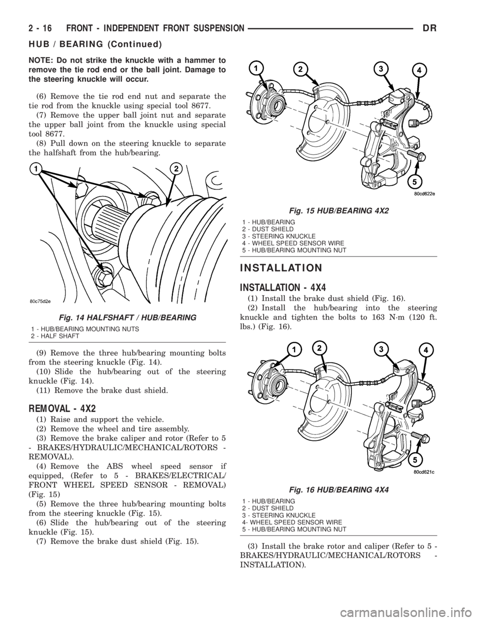
(9) Remove the three hub/bearing mounting bolts
from the steering knuckle (Fig. 14).
(10) Slide the hub/bearing out of the steering
knuckle (Fig. 14).
(11) Remove the brake dust shield.
REMOVAL - 4X2
(1) Raise and support the vehicle.
(2) Remove the wheel and tire assembly.
(3) Remove the brake caliper and rotor (Refer to 5
- BRAKES/HYDRAULIC/MECHANICAL/ROTORS -
REMOVAL).
(4) Remove the ABS wheel speed sensor if
equipped, (Refer to 5 - BRAKES/ELECTRICAL/
FRONT WHEEL SPEED SENSOR - REMOVAL)
(Fig. 15)
(5) Remove the three hub/bearing mounting bolts
from the steering knuckle (Fig. 15).
(6) Slide the hub/bearing out of the steering
knuckle (Fig. 15).
(7) Remove the brake dust shield (Fig. 15).
INSTALLATION
INSTALLATION - 4X4
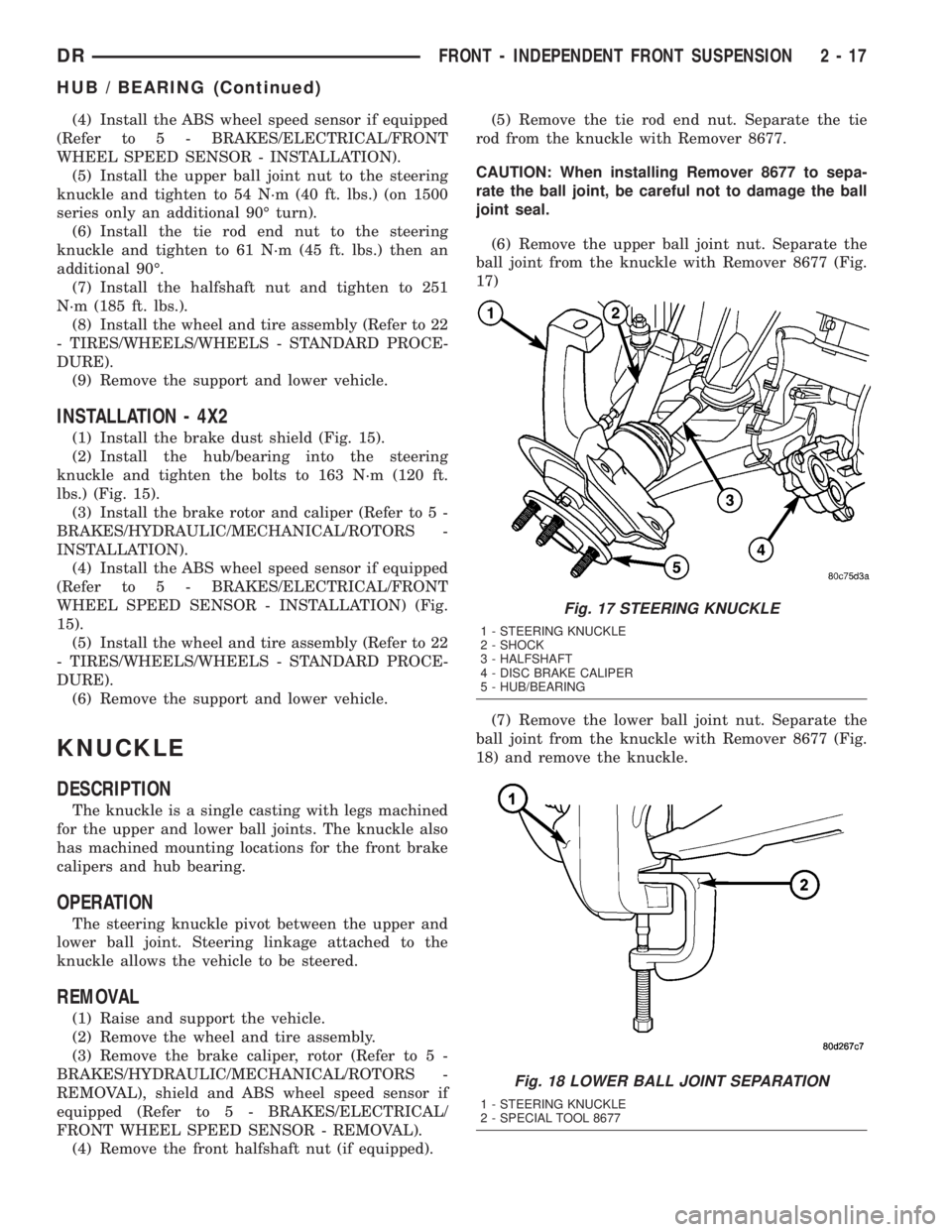
(1) Install the brake dust shield (Fig. 16).
(2) Install the hub/bearing into the steering
knuckle and tighten the bolts to 163 N´m (120 ft.
lbs.) (Fig. 16).
(3) Install the brake rotor and caliper (Refer to 5 -
BRAKES/HYDRAULIC/MECHANICAL/ROTORS -
INSTALLATION).
Fig. 14 HALFSHAFT / HUB/BEARING
1 - HUB/BEARING MOUNTING NUTS
2 - HALF SHAFT
Fig. 15 HUB/BEARING 4X2
1 - HUB/BEARING
2 - DUST SHIELD
3 - STEERING KNUCKLE
4 - WHEEL SPEED SENSOR WIRE
5 - HUB/BEARING MOUNTING NUT
Fig. 16 HUB/BEARING 4X4
1 - HUB/BEARING
2 - DUST SHIELD
3 - STEERING KNUCKLE
4- WHEEL SPEED SENSOR WIRE
5 - HUB/BEARING MOUNTING NUT
2 - 16 FRONT - INDEPENDENT FRONT SUSPENSIONDR
HUB / BEARING (Continued)
Page 46 of 2895
(4) Install the ABS wheel speed sensor if equipped
(Refer to 5 - BRAKES/ELECTRICAL/FRONT
WHEEL SPEED SENSOR - INSTALLATION).
(5) Install the upper ball joint nut to the steering
knuckle and tighten to 54 N´m (40 ft. lbs.) (on 1500
series only an additional 90É turn).
(6) Install the tie rod end nut to the steering
knuckle and tighten to 61 N´m (45 ft. lbs.) then an
additional 90É.
(7) Install the halfshaft nut and tighten to 251
N´m (185 ft. lbs.).
(8) Install the wheel and tire assembly (Refer to 22
- TIRES/WHEELS/WHEELS - STANDARD PROCE-
DURE).
(9) Remove the support and lower vehicle.
INSTALLATION - 4X2
(1) Install the brake dust shield (Fig. 15).
(2) Install the hub/bearing into the steering
knuckle and tighten the bolts to 163 N´m (120 ft.
lbs.) (Fig. 15).
(3) Install the brake rotor and caliper (Refer to 5 -
BRAKES/HYDRAULIC/MECHANICAL/ROTORS -
INSTALLATION).
(4) Install the ABS wheel speed sensor if equipped
(Refer to 5 - BRAKES/ELECTRICAL/FRONT
WHEEL SPEED SENSOR - INSTALLATION) (Fig.
15).
(5) Install the wheel and tire assembly (Refer to 22
- TIRES/WHEELS/WHEELS - STANDARD PROCE-
DURE).
(6) Remove the support and lower vehicle.
KNUCKLE
DESCRIPTION
The knuckle is a single casting with legs machined
for the upper and lower ball joints. The knuckle also
has machined mounting locations for the front brake
calipers and hub bearing.
OPERATION
The steering knuckle pivot between the upper and
lower ball joint. Steering linkage attached to the
knuckle allows the vehicle to be steered.
REMOVAL
(1) Raise and support the vehicle.
(2) Remove the wheel and tire assembly.
(3) Remove the brake caliper, rotor (Refer to 5 -
BRAKES/HYDRAULIC/MECHANICAL/ROTORS -
REMOVAL), shield and ABS wheel speed sensor if
equipped (Refer to 5 - BRAKES/ELECTRICAL/
FRONT WHEEL SPEED SENSOR - REMOVAL).
(4) Remove the front halfshaft nut (if equipped).(5) Remove the tie rod end nut. Separate the tie
rod from the knuckle with Remover 8677.
CAUTION: When installing Remover 8677 to sepa-
rate the ball joint, be careful not to damage the ball
joint seal.
(6) Remove the upper ball joint nut. Separate the
ball joint from the knuckle with Remover 8677 (Fig.
17)
(7) Remove the lower ball joint nut. Separate the
ball joint from the knuckle with Remover 8677 (Fig.
18) and remove the knuckle.
Fig. 17 STEERING KNUCKLE
1 - STEERING KNUCKLE
2 - SHOCK
3 - HALFSHAFT
4 - DISC BRAKE CALIPER
5 - HUB/BEARING
Fig. 18 LOWER BALL JOINT SEPARATION
1 - STEERING KNUCKLE
2 - SPECIAL TOOL 8677
DRFRONT - INDEPENDENT FRONT SUSPENSION 2 - 17
HUB / BEARING (Continued)
Page 47 of 2895
(8) Remove the hub/bearing from the steering
knuckle (Refer to 2 - SUSPENSION/FRONT/HUB /
BEARING - REMOVAL).
INSTALLATION
CAUTION: The ball joint stud tapers must be
CLEAN and DRY before installing the knuckle.
Clean the stud tapers with mineral spirits to remove
dirt and grease.
NOTE: When installing hub/bearing with ABS
brakes, position the speed sensor opening towards
the front of the vehicle.
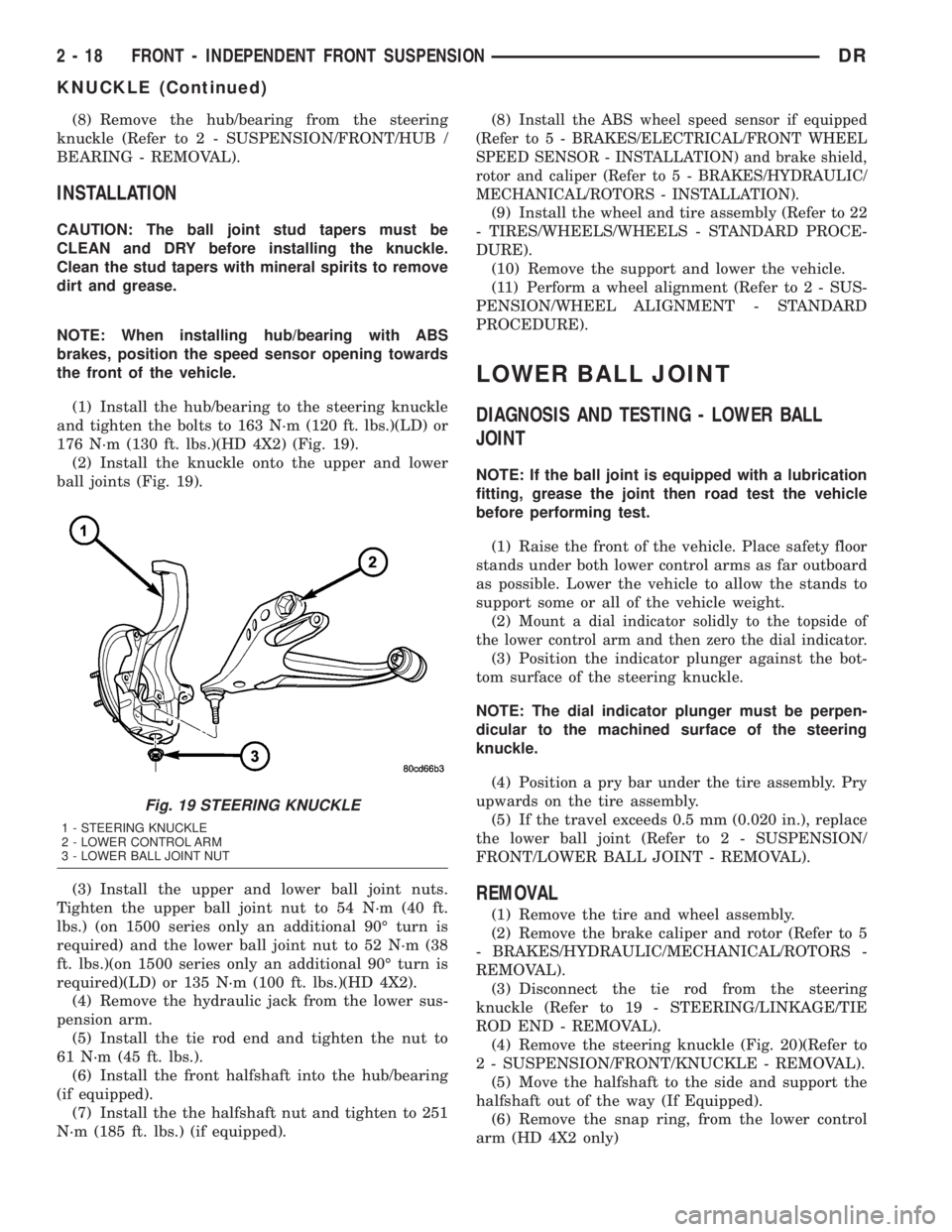
(1) Install the hub/bearing to the steering knuckle
and tighten the bolts to 163 N´m (120 ft. lbs.)(LD) or
176 N´m (130 ft. lbs.)(HD 4X2) (Fig. 19).
(2) Install the knuckle onto the upper and lower
ball joints (Fig. 19).
(3) Install the upper and lower ball joint nuts.
Tighten the upper ball joint nut to 54 N´m (40 ft.
lbs.) (on 1500 series only an additional 90É turn is
required) and the lower ball joint nut to 52 N´m (38
ft. lbs.)(on 1500 series only an additional 90É turn is
required)(LD) or 135 N´m (100 ft. lbs.)(HD 4X2).
(4) Remove the hydraulic jack from the lower sus-
pension arm.
(5) Install the tie rod end and tighten the nut to
61 N´m (45 ft. lbs.).
(6) Install the front halfshaft into the hub/bearing
(if equipped).
(7) Install the the halfshaft nut and tighten to 251
N´m (185 ft. lbs.) (if equipped).(8)
Install the ABS wheel speed sensor if equipped
(Refer to 5 - BRAKES/ELECTRICAL/FRONT WHEEL
SPEED SENSOR - INSTALLATION) and brake shield,
rotor and caliper (Refer to 5 - BRAKES/HYDRAULIC/
MECHANICAL/ROTORS - INSTALLATION).
(9) Install the wheel and tire assembly (Refer to 22
- TIRES/WHEELS/WHEELS - STANDARD PROCE-
DURE).
(10) Remove the support and lower the vehicle.
(11) Perform a wheel alignment (Refer to 2 - SUS-
PENSION/WHEEL ALIGNMENT - STANDARD
PROCEDURE).
LOWER BALL JOINT
DIAGNOSIS AND TESTING - LOWER BALL
JOINT
NOTE: If the ball joint is equipped with a lubrication
fitting, grease the joint then road test the vehicle
before performing test.
(1) Raise the front of the vehicle. Place safety floor
stands under both lower control arms as far outboard
as possible. Lower the vehicle to allow the stands to
support some or all of the vehicle weight.
(2)
Mount a dial indicator solidly to the topside of
the lower control arm and then zero the dial indicator.
(3) Position the indicator plunger against the bot-
tom surface of the steering knuckle.
NOTE: The dial indicator plunger must be perpen-
dicular to the machined surface of the steering
knuckle.
(4) Position a pry bar under the tire assembly. Pry
upwards on the tire assembly.
(5) If the travel exceeds 0.5 mm (0.020 in.), replace
the lower ball joint (Refer to 2 - SUSPENSION/
FRONT/LOWER BALL JOINT - REMOVAL).
REMOVAL
(1) Remove the tire and wheel assembly.
(2) Remove the brake caliper and rotor (Refer to 5
- BRAKES/HYDRAULIC/MECHANICAL/ROTORS -
REMOVAL).
(3) Disconnect the tie rod from the steering
knuckle (Refer to 19 - STEERING/LINKAGE/TIE
ROD END - REMOVAL).
(4) Remove the steering knuckle (Fig. 20)(Refer to
2 - SUSPENSION/FRONT/KNUCKLE - REMOVAL).
(5) Move the halfshaft to the side and support the
halfshaft out of the way (If Equipped).
(6) Remove the snap ring, from the lower control
arm (HD 4X2 only)
Fig. 19 STEERING KNUCKLE
1 - STEERING KNUCKLE
2 - LOWER CONTROL ARM
3 - LOWER BALL JOINT NUT
2 - 18 FRONT - INDEPENDENT FRONT SUSPENSIONDR
KNUCKLE (Continued)
Page 59 of 2895
HUB / BEARING
REMOVAL
(1) Raise and support the vehicle.
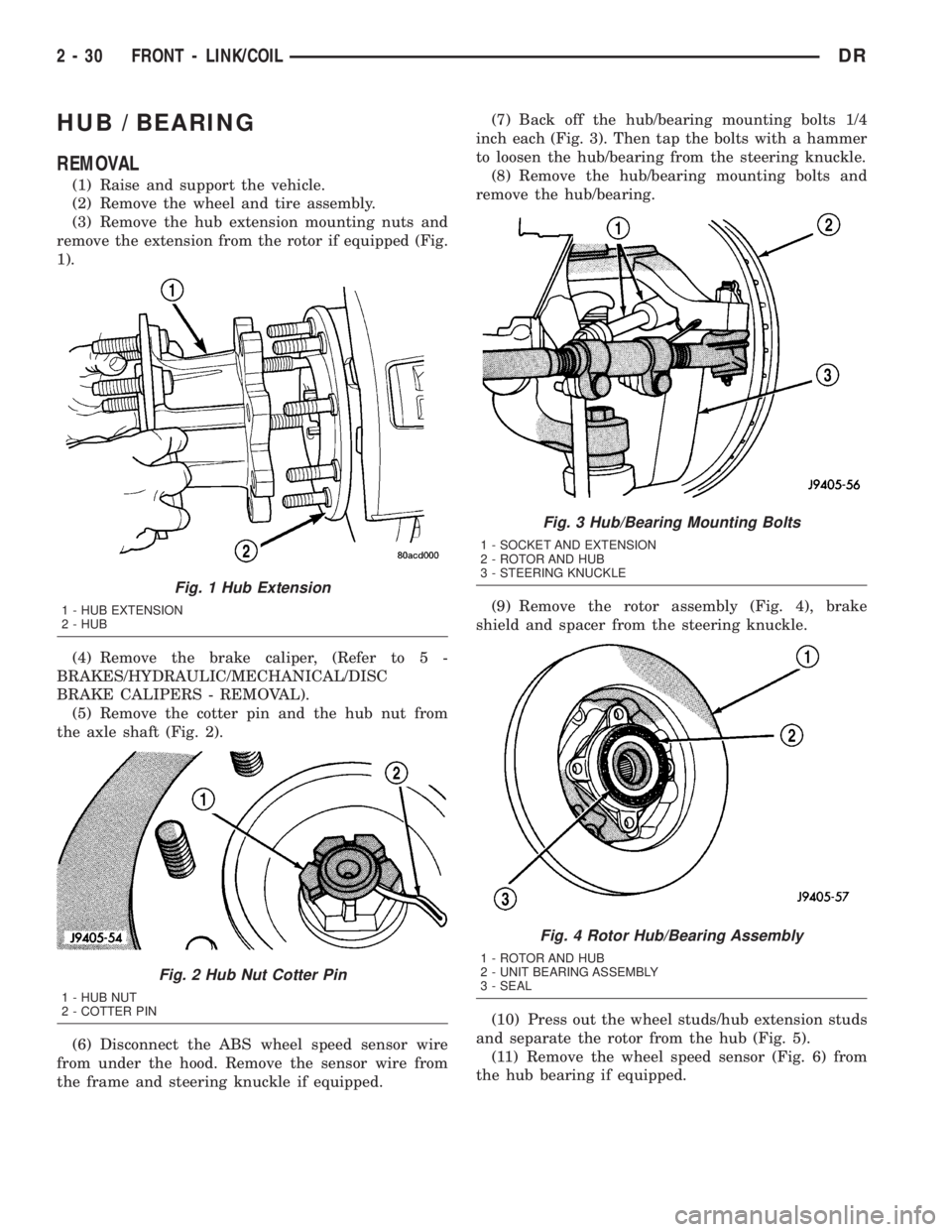
(2) Remove the wheel and tire assembly.
(3) Remove the hub extension mounting nuts and
remove the extension from the rotor if equipped (Fig.
1).
(4) Remove the brake caliper, (Refer to 5 -
BRAKES/HYDRAULIC/MECHANICAL/DISC
BRAKE CALIPERS - REMOVAL).
(5) Remove the cotter pin and the hub nut from
the axle shaft (Fig. 2).
(6) Disconnect the ABS wheel speed sensor wire
from under the hood. Remove the sensor wire from
the frame and steering knuckle if equipped.(7) Back off the hub/bearing mounting bolts 1/4
inch each (Fig. 3). Then tap the bolts with a hammer
to loosen the hub/bearing from the steering knuckle.
(8) Remove the hub/bearing mounting bolts and
remove the hub/bearing.
(9) Remove the rotor assembly (Fig. 4), brake
shield and spacer from the steering knuckle.
(10) Press out the wheel studs/hub extension studs
and separate the rotor from the hub (Fig. 5).
(11) Remove the wheel speed sensor (Fig. 6) from
the hub bearing if equipped.
Fig. 1 Hub Extension
1 - HUB EXTENSION
2 - HUB
Fig. 2 Hub Nut Cotter Pin
1 - HUB NUT
2 - COTTER PIN
Fig. 3 Hub/Bearing Mounting Bolts
1 - SOCKET AND EXTENSION
2 - ROTOR AND HUB
3 - STEERING KNUCKLE
Fig. 4 Rotor Hub/Bearing Assembly
1 - ROTOR AND HUB
2 - UNIT BEARING ASSEMBLY
3 - SEAL
2 - 30 FRONT - LINK/COILDR
Page 60 of 2895
INSTALLATION
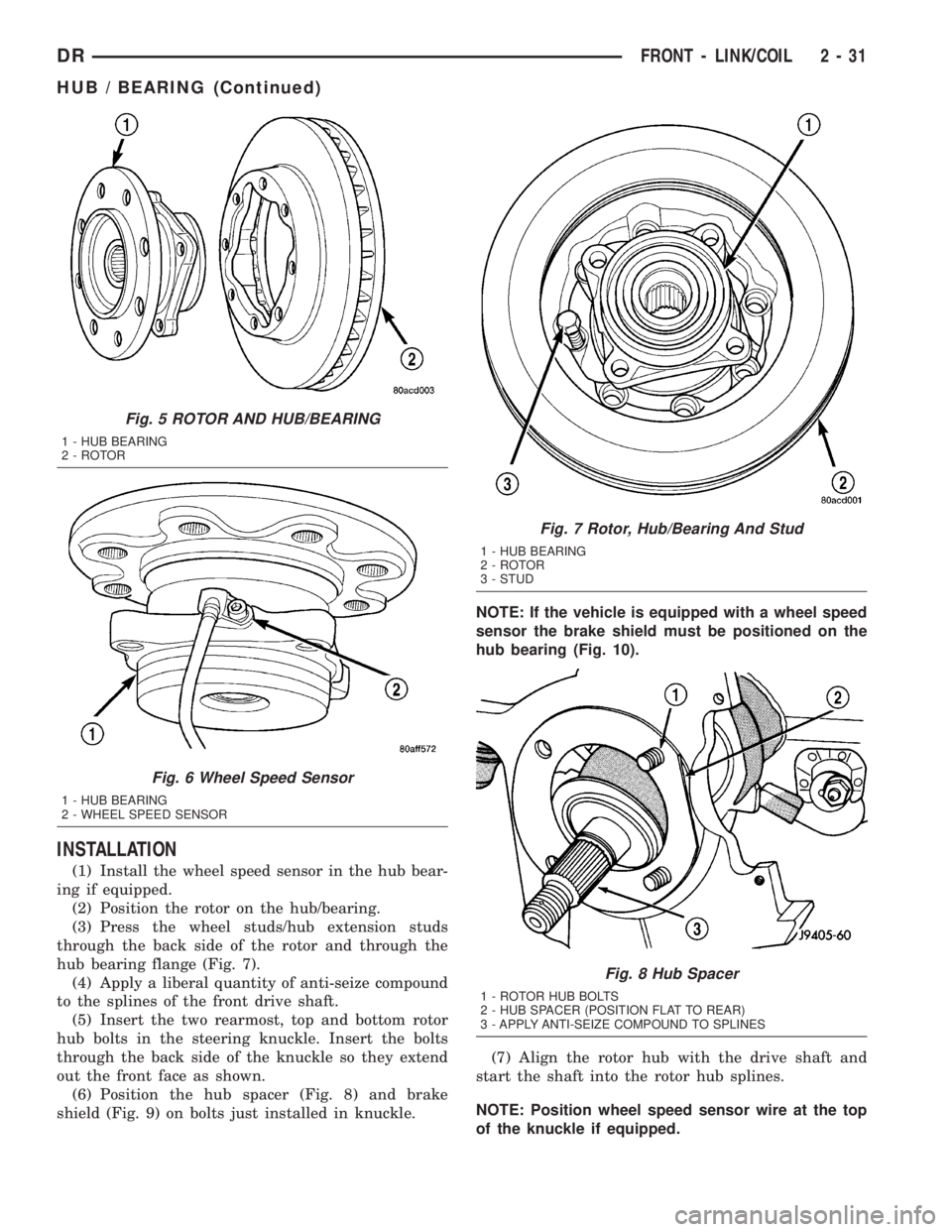
(1) Install the wheel speed sensor in the hub bear-
ing if equipped.
(2) Position the rotor on the hub/bearing.
(3) Press the wheel studs/hub extension studs
through the back side of the rotor and through the
hub bearing flange (Fig. 7).
(4) Apply a liberal quantity of anti-seize compound
to the splines of the front drive shaft.
(5) Insert the two rearmost, top and bottom rotor
hub bolts in the steering knuckle. Insert the bolts
through the back side of the knuckle so they extend
out the front face as shown.
(6) Position the hub spacer (Fig. 8) and brake
shield (Fig. 9) on bolts just installed in knuckle.NOTE: If the vehicle is equipped with a wheel speed
sensor the brake shield must be positioned on the
hub bearing (Fig. 10).
(7) Align the rotor hub with the drive shaft and
start the shaft into the rotor hub splines.
NOTE: Position wheel speed sensor wire at the top
of the knuckle if equipped.
Fig. 5 ROTOR AND HUB/BEARING
1 - HUB BEARING
2 - ROTOR
Fig. 6 Wheel Speed Sensor
1 - HUB BEARING
2 - WHEEL SPEED SENSOR
Fig. 7 Rotor, Hub/Bearing And Stud
1 - HUB BEARING
2 - ROTOR
3 - STUD
Fig. 8 Hub Spacer
1 - ROTOR HUB BOLTS
2 - HUB SPACER (POSITION FLAT TO REAR)
3 - APPLY ANTI-SEIZE COMPOUND TO SPLINES
DRFRONT - LINK/COIL 2 - 31
HUB / BEARING (Continued)
Page 61 of 2895
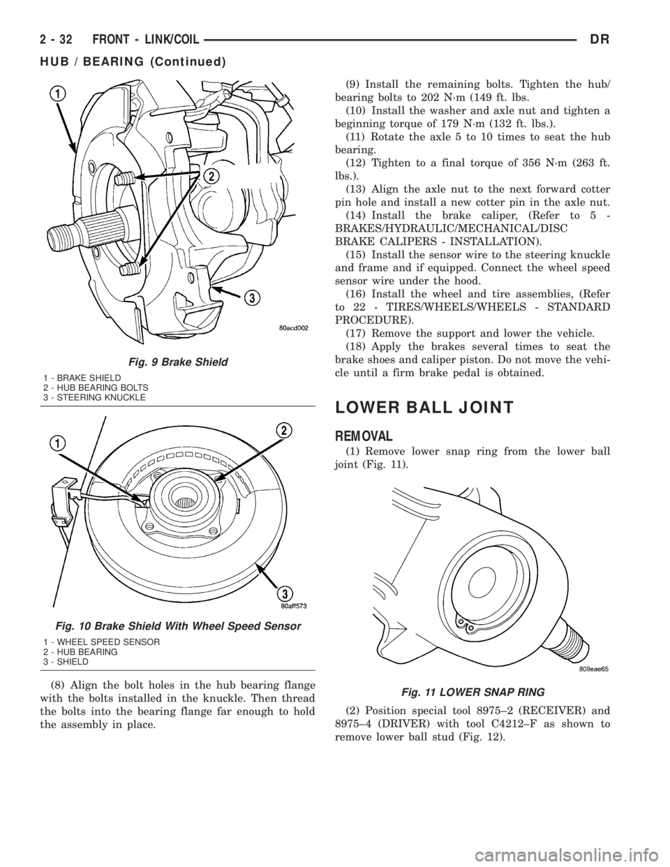
(8) Align the bolt holes in the hub bearing flange
with the bolts installed in the knuckle. Then thread
the bolts into the bearing flange far enough to hold
the assembly in place.(9) Install the remaining bolts. Tighten the hub/
bearing bolts to 202 N´m (149 ft. lbs.
(10) Install the washer and axle nut and tighten a
beginning torque of 179 N´m (132 ft. lbs.).
(11) Rotate the axle 5 to 10 times to seat the hub
bearing.
(12) Tighten to a final torque of 356 N´m (263 ft.
lbs.).
(13) Align the axle nut to the next forward cotter
pin hole and install a new cotter pin in the axle nut.
(14) Install the brake caliper, (Refer to 5 -
BRAKES/HYDRAULIC/MECHANICAL/DISC
BRAKE CALIPERS - INSTALLATION).
(15) Install the sensor wire to the steering knuckle
and frame and if equipped. Connect the wheel speed
sensor wire under the hood.
(16) Install the wheel and tire assemblies, (Refer
to 22 - TIRES/WHEELS/WHEELS - STANDARD
PROCEDURE).
(17) Remove the support and lower the vehicle.
(18) Apply the brakes several times to seat the
brake shoes and caliper piston. Do not move the vehi-
cle until a firm brake pedal is obtained.
LOWER BALL JOINT
REMOVAL
(1) Remove lower snap ring from the lower ball
joint (Fig. 11).
(2) Position special tool 8975±2 (RECEIVER) and
8975±4 (DRIVER) with tool C4212±F as shown to
remove lower ball stud (Fig. 12).
Fig. 9 Brake Shield
1 - BRAKE SHIELD
2 - HUB BEARING BOLTS
3 - STEERING KNUCKLE
Fig. 10 Brake Shield With Wheel Speed Sensor
1 - WHEEL SPEED SENSOR
2 - HUB BEARING
3 - SHIELD
Fig. 11 LOWER SNAP RING
2 - 32 FRONT - LINK/COILDR
HUB / BEARING (Continued)
Page 63 of 2895
KNUCKLE
REMOVAL
(1) Remove the hub bearing (Refer to 2 - SUSPEN-
SION/FRONT/HUB / BEARING - REMOVAL).
(2) Remove tie-rod or drag link end from the steer-
ing knuckle arm.
(3) Remove the ABS sensor wire and bracket from
knuckle. Refer to Brakes, for proper procedures.
(4) Remove the cotter pin from the upper ball stud
nut. Remove the upper and lower ball stud nuts.
(5) Strike the steering knuckle with a brass ham-
mer to loosen.
(6) Remove knuckle from axle tube yokes.
INSTALLATION
(1) Position the steering knuckle on the ball studs.
(2) Install and tighten lower ball stud nut to 47
N´m (35 ft. lbs.) torque. Do not install cotter pin at
this time.
(3) Install and tighten upper ball stud nut to 94
N´m (70 ft. lbs.) torque. Advance nut to next slot to
line up hole and install new cotter pin.
(4) Retorque lower ball stud nut to 190±217 N´m
(140±160 ft. lbs.) torque. Advance nut to next slot to
line up hole and install new cotter pin.
(5) Install the hub bearing (Refer to 2 - SUSPEN-
SION/FRONT/HUB / BEARING - INSTALLATION).
(6) Install tie-rod or drag link end onto the steer-
ing knuckle arm.
(7) Install the ABS sensor wire and bracket to the
knuckle. Refer to Brakes, for proper procedure.
UPPER SUSPENSION ARM
REMOVAL
REMOVAL - LEFT
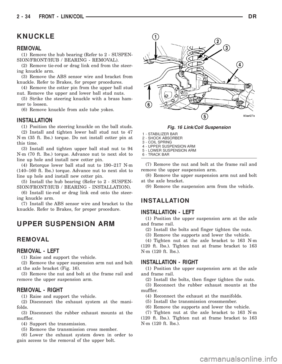
(1) Raise and support the vehicle.
(2) Remove the upper suspension arm nut and bolt
at the axle bracket (Fig. 16).
(3) Remove the nut and bolt at the frame rail and
remove the upper suspension arm.
REMOVAL - RIGHT
(1) Raise and support the vehicle.
(2) Disconnect the exhaust system at the mani-
folds.
(3) Disconnect the rubber exhaust mounts at the
muffler.
(4) Support the transmission.
(5) Remove the transmission cross member.
(6) Lower the exhaust system down in order to
gain access to the removal of the upper bolt.(7) Remove the nut and bolt at the frame rail and
remove the upper suspension arm.
(8) Remove the upper suspension arm nut and bolt
at the axle bracket.
(9) Remove the suspension arm from the vehicle.
INSTALLATION
INSTALLATION - LEFT
(1) Position the upper suspension arm at the axle
and frame rail.
(2) Install the bolts and finger tighten the nuts.
(3) Remove the supports and lower the vehicle.
(4) Tighten nut at the axle bracket to 163 N´m
(120 ft. lbs.). Tighten nut at frame bracket to 163
N´m (120 ft. lbs.).
INSTALLATION - RIGHT
(1) Position the upper suspension arm at the axle
and frame rail.
(2) Install the bolts, then finger tighten the nuts.
(3) Reconnect the rubber exhaust mounts at the
muffler.
(4) Reconnect the exhaust at the manifolds.
(5) Install the transmission crossmember.
(6) Remove the supports and lower the vehicle.
(7) Tighten nut at the axle bracket to 163 N´m
(120 ft. lbs.). Tighten nut at frame bracket to 163
N´m (120 ft. lbs.).
Fig. 16 Link/Coil Suspension
1 - STABILIZER BAR
2 - SHOCK ABSORBER
3 - COIL SPRING
4 - UPPER SUSPENSION ARM
5 - LOWER SUSPENSION ARM
6 - TRACK BAR
2 - 34 FRONT - LINK/COILDR
Page 121 of 2895
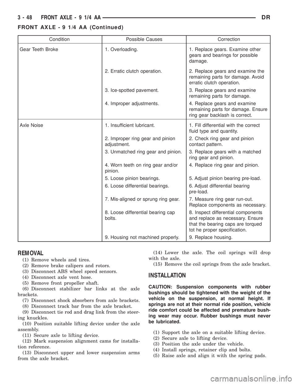
Condition Possible Causes Correction
Gear Teeth Broke 1. Overloading. 1. Replace gears. Examine other
gears and bearings for possible
damage.
2. Erratic clutch operation. 2. Replace gears and examine the
remaining parts for damage. Avoid
erratic clutch operation.
3. Ice-spotted pavement. 3. Replace gears and examine
remaining parts for damage.
4. Improper adjustments. 4. Replace gears and examine
remaining parts for damage. Ensure
ring gear backlash is correct.
Axle Noise 1. Insufficient lubricant. 1. Fill differential with the correct
fluid type and quantity.
2. Improper ring gear and pinion
adjustment.2. Check ring gear and pinion
contact pattern.
3. Unmatched ring gear and pinion. 3. Replace gears with a matched
ring gear and pinion.
4. Worn teeth on ring gear and/or
pinion.4. Replace ring gear and pinion.
5. Loose pinion bearings. 5. Adjust pinion bearing pre-load.
6. Loose differential bearings. 6. Adjust differential bearing
pre-load.
7. Mis-aligned or sprung ring gear. 7. Measure ring gear run-out.
Replace components as necessary.
8. Loose differential bearing cap
bolts.8. Inspect differential components
and replace as necessary. Ensure
that the bearing caps are torqued
tot he proper specification.
9. Housing not machined properly. 9. Replace housing.
REMOVAL
(1) Remove wheels and tires.
(2) Remove brake calipers and rotors.
(3) Disconnect ABS wheel speed sensors.
(4) Disconnect axle vent hose.
(5) Remove front propeller shaft.
(6) Disconnect stabilizer bar links at the axle
brackets.
(7) Disconnect shock absorbers from axle brackets.
(8) Disconnect track bar from the axle bracket.
(9) Disconnect tie rod and drag link from the steer-
ing knuckles.
(10) Position suitable lifting device under the axle
assembly.
(11) Secure axle to lifting device.
(12) Mark suspension alignment cams for installa-
tion reference.
(13) Disconnect upper and lower suspension arms
from the axle bracket.(14) Lower the axle. The coil springs will drop
with the axle.
(15) Remove the coil springs from the axle bracket.
INSTALLATION
CAUTION: Suspension components with rubber
bushings should be tightened with the weight of the
vehicle on the suspension, at normal height. If
springs are not at their normal ride position, vehicle
ride comfort could be affected and premature bush-
ing wear may occur. Rubber bushings must never
be lubricated.
(1) Support the axle on a suitable lifting device.
(2) Secure axle to lifting device.
(3) Position the axle under the vehicle.
(4) Install springs, retainer clip and bolts.
(5) Raise axle and align it with the spring pads.
3 - 48 FRONT AXLE - 9 1/4 AADR
FRONT AXLE - 9 1/4 AA (Continued)
Page 122 of 2895
(6) Position upper and lower suspension arms in
the axle brackets. Install bolts, nuts and align the
suspension alignment cams to the reference marks.
Do not tighten at this time.
(7) Connect track bar to the axle bracket and
install the bolt. Do not tighten at this time.
(8) Install shock absorber and tighten bolts to 121
N´m (89 ft. lbs.).
(9) Install stabilizer bar link to the axle bracket.
Tighten the nut to 68 N´m (50 ft. lbs.).
(10) Install drag link and tie rod to the steering
knuckles and tighten the nuts to 108 N´m (80 ft.
lbs.).
(11) Install ABS wheel speed sensors.
(12) Install rotors and brake calipers.
(13) Connect the axle vent hose.
(14) Install front propeller shaft.
(15) Check and add differential lubricant, if neces-
sary.
(16) Install wheel and tire assemblies.
(17) Remove lower the vehicle.
(18) Tighten upper suspension arm nuts at axle to
149 N´m (110 ft. lbs.). Tighten upper suspension arm
nuts at frame to 149 N´m (110 ft. lbs.).
(19) Tighten lower suspension arm nuts at axle to
190 N´m (140 ft. lbs.). Tighten the lower suspension
arm nuts at frame to 190 N´m (140 ft. lbs.).
(20) Tighten track bar bolt at the axle bracket to
176 N´m (130 ft. lbs.).
(21) Check front wheel alignment.
ADJUSTMENTS
Ring and pinion gears are supplied as matched
sets only. Compensation for pinion depth variance is
achieved with a select shim. The shim is located
between the rear pinion bearing and the pinion gear
head.
PINION DEPTH MEASUREMENT AND ADJUSTMENT
Measurements are taken with pinion bearing cups
and pinion bearings installed in the housing. Take
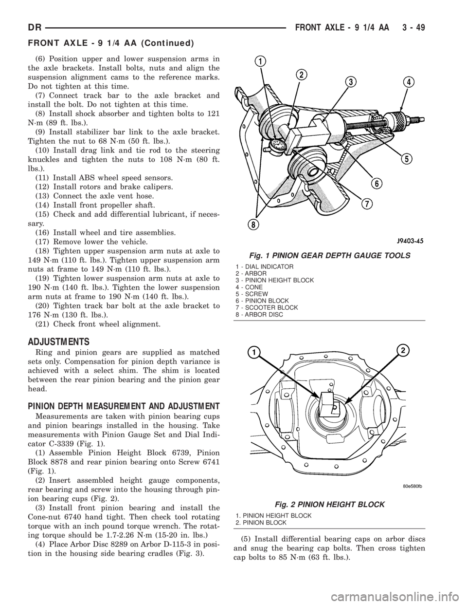
measurements with Pinion Gauge Set and Dial Indi-
cator C-3339 (Fig. 1).
(1) Assemble Pinion Height Block 6739, Pinion
Block 8878 and rear pinion bearing onto Screw 6741
(Fig. 1).
(2) Insert assembled height gauge components,
rear bearing and screw into the housing through pin-
ion bearing cups (Fig. 2).
(3) Install front pinion bearing and install the
Cone-nut 6740 hand tight. Then check tool rotating
torque with an inch pound torque wrench. The rotat-
ing torque should be 1.7-2.26 N´m (15-20 in. lbs.)
(4) Place Arbor Disc 8289 on Arbor D-115-3 in posi-
tion in the housing side bearing cradles (Fig. 3).(5) Install differential bearing caps on arbor discs
and snug the bearing cap bolts. Then cross tighten
cap bolts to 85 N´m (63 ft. lbs.).
Fig. 1 PINION GEAR DEPTH GAUGE TOOLS
1 - DIAL INDICATOR
2 - ARBOR
3 - PINION HEIGHT BLOCK
4 - CONE
5 - SCREW
6 - PINION BLOCK
7 - SCOOTER BLOCK
8 - ARBOR DISC
Fig. 2 PINION HEIGHT BLOCK
1. PINION HEIGHT BLOCK
2. PINION BLOCK
DRFRONT AXLE - 9 1/4 AA 3 - 49
FRONT AXLE - 9 1/4 AA (Continued)