DODGE RAM 2003 Service Repair Manual
Manufacturer: DODGE, Model Year: 2003, Model line: RAM, Model: DODGE RAM 2003Pages: 2895, PDF Size: 83.15 MB
Page 2371 of 2895

HYDRAULIC FLOW IN MANUAL SECOND
21 - 532 AUTOMATIC TRANSMISSION - 45RFE/545RFEDR
AUTOMATIC TRANSMISSION - 45RFE/545RFE (Continued)
Page 2372 of 2895

HYDRAULIC FLOW IN MANUAL SECOND (FAILSAFE)
DRAUTOMATIC TRANSMISSION - 45RFE/545RFE 21 - 533
AUTOMATIC TRANSMISSION - 45RFE/545RFE (Continued)
Page 2373 of 2895
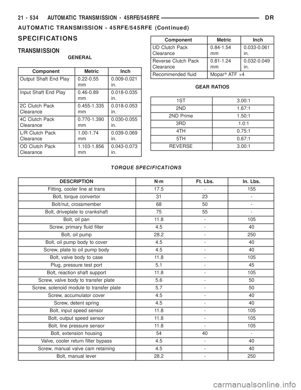
SPECIFICATIONS
TRANSMISSION
GENERAL
Component Metric Inch
Output Shaft End Play 0.22-0.55
mm0.009-0.021
in.
Input Shaft End Play 0.46-0.89
mm0.018-0.035
in.
2C Clutch Pack
Clearance0.455-1.335
mm0.018-0.053
in.
4C Clutch Pack
Clearance0.770-1.390
mm0.030-0.055
in.
L/R Clutch Pack
Clearance1.00-1.74
mm0.039-0.069
in.
OD Clutch Pack
Clearance1.103-1.856
mm0.043-0.073
in.
Component Metric Inch
UD Clutch Pack
Clearance0.84-1.54
mm0.033-0.061
in.
Reverse Clutch Pack
Clearance0.81-1.24
mm0.032-0.049
in.
Recommended fluid MoparTAT F + 4
GEAR RATIOS
1ST 3.00:1
2ND 1.67:1
2ND Prime 1.50:1
3RD 1.0:1
4TH 0.75:1
5TH 0.67:1
REVERSE 3.00:1
TORQUE SPECIFICATIONS
DESCRIPTION N´m Ft. Lbs. In. Lbs.
Fitting, cooler line at trans 17.5 - 155
Bolt, torque convertor 31 23 -
Bolt/nut, crossmember 68 50 -
Bolt, driveplate to crankshaft 75 55 -
Bolt, oil pan 11.8 - 105
Screw, primary fluid filter 4.5 - 40
Bolt, oil pump 28.2 - 250
Bolt, oil pump body to cover 4.5 - 40
Screw, plate to oil pump body 4.5 - 40
Bolt, valve body to case 11.8 - 105
Plug, pressure test port 5.1 - 45
Bolt, reaction shaft support 11.8 - 105
Screw, valve body to transfer plate 5.6 - 50
Screw, solenoid module to transfer plate 5.7 - 50
Screw, accumulator cover 4.5 - 40
Screw, detent spring 4.5 - 40
Bolt, input speed sensor 11.8 - 105
Bolt, output speed sensor 11.8 - 105
Bolt, line pressure sensor 11.8 - 105
Bolt, extension housing 54 40 -
Valve, cooler return filter bypass 4.5 - 40
Screw, manual valve cam retaining 4.5 - 40
Bolt, manual lever 28.2 - 250
21 - 534 AUTOMATIC TRANSMISSION - 45RFE/545RFEDR
AUTOMATIC TRANSMISSION - 45RFE/545RFE (Continued)
Page 2374 of 2895
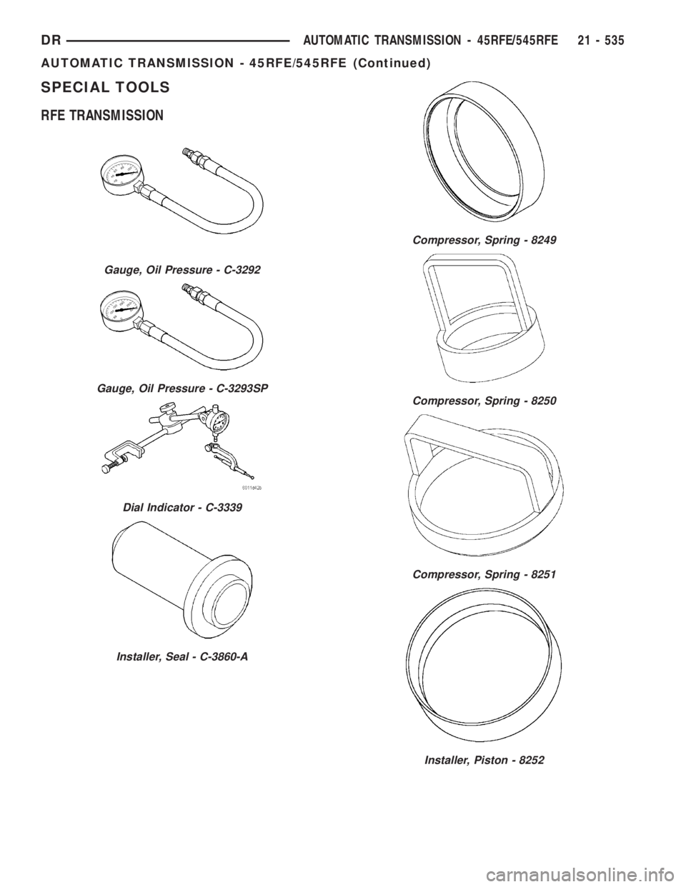
SPECIAL TOOLS
RFE TRANSMISSION
Gauge, Oil Pressure - C-3292
Gauge, Oil Pressure - C-3293SP
Dial Indicator - C-3339
Installer, Seal - C-3860-A
Compressor, Spring - 8249
Compressor, Spring - 8250
Compressor, Spring - 8251
Installer, Piston - 8252
DRAUTOMATIC TRANSMISSION - 45RFE/545RFE 21 - 535
AUTOMATIC TRANSMISSION - 45RFE/545RFE (Continued)
Page 2375 of 2895
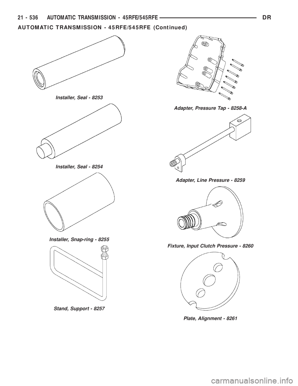
Installer, Seal - 8253
Installer, Seal - 8254
Installer, Snap-ring - 8255
Stand, Support - 8257
Adapter, Pressure Tap - 8258-A
Adapter, Line Pressure - 8259
Fixture, Input Clutch Pressure - 8260
Plate, Alignment - 8261
21 - 536 AUTOMATIC TRANSMISSION - 45RFE/545RFEDR
AUTOMATIC TRANSMISSION - 45RFE/545RFE (Continued)
Page 2376 of 2895
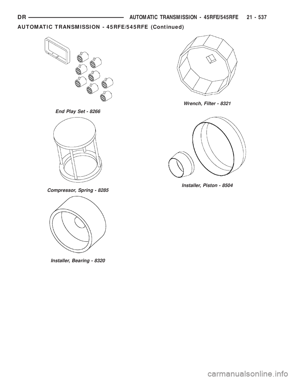
Wrench, Filter - 8321
Installer, Piston - 8504
End Play Set - 8266
Compressor, Spring - 8285
Installer, Bearing - 8320
DRAUTOMATIC TRANSMISSION - 45RFE/545RFE 21 - 537
AUTOMATIC TRANSMISSION - 45RFE/545RFE (Continued)
Page 2377 of 2895
4C RETAINER/BULKHEAD
DISASSEMBLY
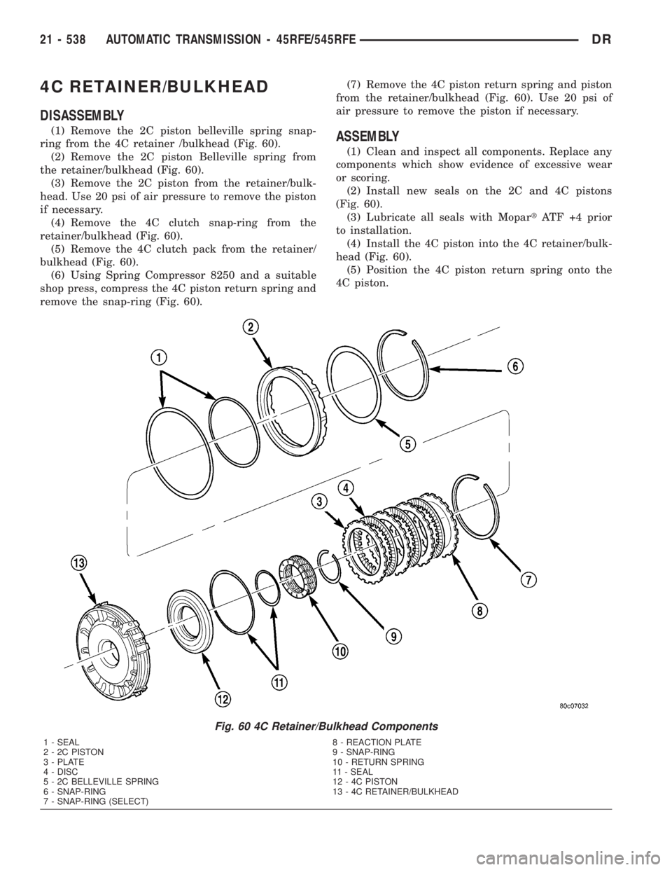
(1) Remove the 2C piston belleville spring snap-
ring from the 4C retainer /bulkhead (Fig. 60).
(2) Remove the 2C piston Belleville spring from
the retainer/bulkhead (Fig. 60).
(3) Remove the 2C piston from the retainer/bulk-
head. Use 20 psi of air pressure to remove the piston
if necessary.
(4) Remove the 4C clutch snap-ring from the
retainer/bulkhead (Fig. 60).
(5) Remove the 4C clutch pack from the retainer/
bulkhead (Fig. 60).
(6) Using Spring Compressor 8250 and a suitable
shop press, compress the 4C piston return spring and
remove the snap-ring (Fig. 60).(7) Remove the 4C piston return spring and piston
from the retainer/bulkhead (Fig. 60). Use 20 psi of
air pressure to remove the piston if necessary.ASSEMBLY
(1) Clean and inspect all components. Replace any
components which show evidence of excessive wear
or scoring.
(2) Install new seals on the 2C and 4C pistons
(Fig. 60).
(3) Lubricate all seals with MopartATF +4 prior
to installation.
(4) Install the 4C piston into the 4C retainer/bulk-
head (Fig. 60).
(5) Position the 4C piston return spring onto the
4C piston.
Fig. 60 4C Retainer/Bulkhead Components
1 - SEAL 8 - REACTION PLATE
2 - 2C PISTON 9 - SNAP-RING
3 - PLATE 10 - RETURN SPRING
4 - DISC 11 - SEAL
5 - 2C BELLEVILLE SPRING 12 - 4C PISTON
6 - SNAP-RING 13 - 4C RETAINER/BULKHEAD
7 - SNAP-RING (SELECT)
21 - 538 AUTOMATIC TRANSMISSION - 45RFE/545RFEDR
Page 2378 of 2895
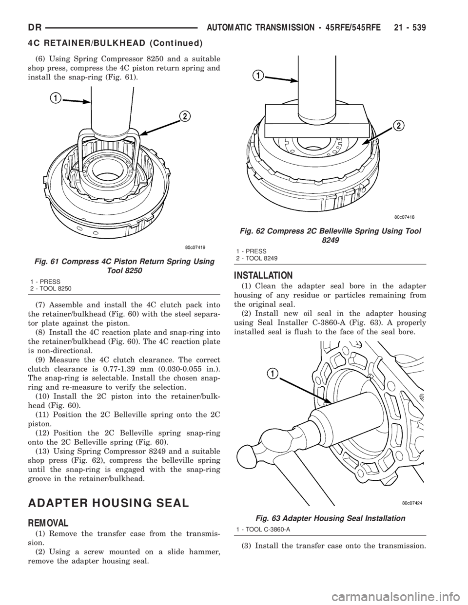
(6) Using Spring Compressor 8250 and a suitable
shop press, compress the 4C piston return spring and
install the snap-ring (Fig. 61).
(7) Assemble and install the 4C clutch pack into
the retainer/bulkhead (Fig. 60) with the steel separa-
tor plate against the piston.
(8) Install the 4C reaction plate and snap-ring into
the retainer/bulkhead (Fig. 60). The 4C reaction plate
is non-directional.
(9) Measure the 4C clutch clearance. The correct
clutch clearance is 0.77-1.39 mm (0.030-0.055 in.).
The snap-ring is selectable. Install the chosen snap-
ring and re-measure to verify the selection.
(10) Install the 2C piston into the retainer/bulk-
head (Fig. 60).
(11) Position the 2C Belleville spring onto the 2C
piston.
(12) Position the 2C Belleville spring snap-ring
onto the 2C Belleville spring (Fig. 60).
(13) Using Spring Compressor 8249 and a suitable
shop press (Fig. 62), compress the belleville spring
until the snap-ring is engaged with the snap-ring
groove in the retainer/bulkhead.
ADAPTER HOUSING SEAL
REMOVAL
(1) Remove the transfer case from the transmis-
sion.
(2) Using a screw mounted on a slide hammer,
remove the adapter housing seal.
INSTALLATION
(1) Clean the adapter seal bore in the adapter
housing of any residue or particles remaining from
the original seal.
(2) Install new oil seal in the adapter housing
using Seal Installer C-3860-A (Fig. 63). A properly
installed seal is flush to the face of the seal bore.
(3) Install the transfer case onto the transmission.
Fig. 61 Compress 4C Piston Return Spring Using
Tool 8250
1 - PRESS
2 - TOOL 8250
Fig. 62 Compress 2C Belleville Spring Using Tool
8249
1 - PRESS
2 - TOOL 8249
Fig. 63 Adapter Housing Seal Installation
1 - TOOL C-3860-A
DRAUTOMATIC TRANSMISSION - 45RFE/545RFE 21 - 539
4C RETAINER/BULKHEAD (Continued)
Page 2379 of 2895
BRAKE TRANSMISSION SHIFT
INTERLOCK SYSTEM
DESCRIPTION
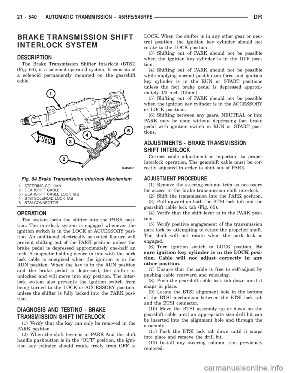
The Brake Transmission Shifter Interlock (BTSI)
(Fig. 64), is a solenoid operated system. It consists of
a solenoid permanently mounted on the gearshift
cable.
OPERATION
The system locks the shifter into the PARK posi-
tion. The interlock system is engaged whenever the
ignition switch is in the LOCK or ACCESSORY posi-
tion. An additional electrically activated feature will
prevent shifting out of the PARK position unless the
brake pedal is depressed approximately one-half an
inch. A magnetic holding device in line with the park
lock cable is energized when the ignition is in the
RUN position. When the key is in the RUN position
and the brake pedal is depressed, the shifter is
unlocked and will move into any position. The inter-
lock system also prevents the ignition switch from
being turned to the LOCK or ACCESSORY position,
unless the shifter is fully locked into the PARK posi-
tion.
DIAGNOSIS AND TESTING - BRAKE
TRANSMISSION SHIFT INTERLOCK
(1) Verify that the key can only be removed in the
PARK position
(2) When the shift lever is in PARK And the shift
handle pushbutton is in the ªOUTº position, the igni-
tion key cylinder should rotate freely from OFF toLOCK. When the shifter is in any other gear or neu-
tral position, the ignition key cylinder should not
rotate to the LOCK position.
(3) Shifting out of PARK should not be possible
when the ignition key cylinder is in the OFF posi-
tion.
(4) Shifting out of PARK should not be possible
while applying normal pushbutton force and ignition
key cylinder is in the RUN or START positions
unless the foot brake pedal is depressed approxi-
mately 1/2 inch (12mm).
(5) Shifting out of PARK should not be possible
when the ignition key cylinder is in the ACCESSORY
or LOCK positions.
(6) Shifting between any gears, NEUTRAL or into
PARK may be done without depressing foot brake
pedal with ignition switch in RUN or START posi-
tions.
ADJUSTMENTS - BRAKE TRANSMISSION
SHIFT INTERLOCK
Correct cable adjustment is important to proper
interlock operation. The gearshift cable must be cor-
rectly adjusted in order to shift out of PARK.
ADJUSTMENT PROCEDURE
(1) Remove the steering column trim as necessary
for access to the brake transmission shift interlock.
(2) Shift the transmission into the PARK position.
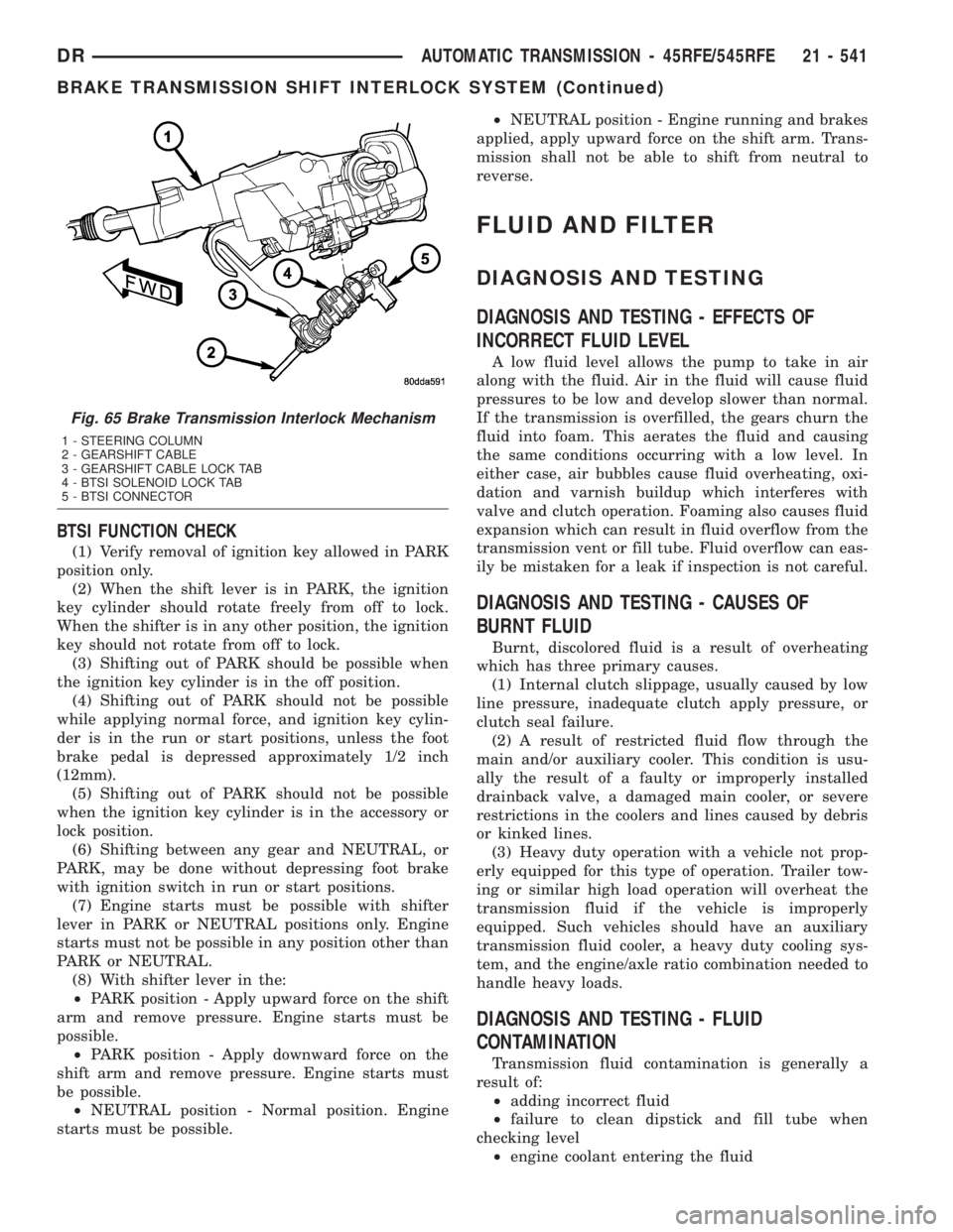
(3) Pull upward on both the BTSI lock tab and the
gearshift cable lock tab (Fig. 65).
(4) Verify that the shift lever is in the PARK posi-
tion.
(5) Verify positive engagement of the transmission
park lock by attempting to rotate the propeller shaft.
The shaft will not rotate when the park lock is
engaged.
(6) Turn ignition switch to LOCK position.Be
sure ignition key cylinder is in the LOCK posi-
tion. Cable will not adjust correctly in any
other position.
(7) Ensure that the cable is free to self-adjust by
pushing cable rearward and releasing.
(8) Push the gearshift cable lock tab down until it
snaps in place.
(9) Locate the BTSI alignment hole in the bottom
of the BTSI mechanism between the BTSI lock tab
and the BTSI connector.
(10) Move the BTSI assembly up or down on the
gearshift cable until an appropriate size drill bit can
be inserted into the alignment hole and through the
assembly.
(11) Push the BTSI lock tab down until it snaps
into place and remove the drill bit.
(12) Install any steering column trim previously
removed.
Fig. 64 Brake Transmission Interlock Mechanism
1 - STEERING COLUMN
2 - GEARSHIFT CABLE
3 - GEARSHIFT CABLE LOCK TAB
4 - BTSI SOLENOID LOCK TAB
5 - BTSI CONNECTOR
21 - 540 AUTOMATIC TRANSMISSION - 45RFE/545RFEDR
Page 2380 of 2895
BTSI FUNCTION CHECK
(1) Verify removal of ignition key allowed in PARK
position only.
(2) When the shift lever is in PARK, the ignition
key cylinder should rotate freely from off to lock.
When the shifter is in any other position, the ignition
key should not rotate from off to lock.
(3) Shifting out of PARK should be possible when
the ignition key cylinder is in the off position.
(4) Shifting out of PARK should not be possible
while applying normal force, and ignition key cylin-
der is in the run or start positions, unless the foot
brake pedal is depressed approximately 1/2 inch
(12mm).
(5) Shifting out of PARK should not be possible
when the ignition key cylinder is in the accessory or
lock position.
(6) Shifting between any gear and NEUTRAL, or
PARK, may be done without depressing foot brake
with ignition switch in run or start positions.
(7) Engine starts must be possible with shifter
lever in PARK or NEUTRAL positions only. Engine
starts must not be possible in any position other than
PARK or NEUTRAL.
(8) With shifter lever in the:
²PARK position - Apply upward force on the shift
arm and remove pressure. Engine starts must be
possible.
²PARK position - Apply downward force on the
shift arm and remove pressure. Engine starts must
be possible.
²NEUTRAL position - Normal position. Engine
starts must be possible.²NEUTRAL position - Engine running and brakes
applied, apply upward force on the shift arm. Trans-
mission shall not be able to shift from neutral to
reverse.
FLUID AND FILTER
DIAGNOSIS AND TESTING
DIAGNOSIS AND TESTING - EFFECTS OF
INCORRECT FLUID LEVEL
A low fluid level allows the pump to take in air
along with the fluid. Air in the fluid will cause fluid
pressures to be low and develop slower than normal.
If the transmission is overfilled, the gears churn the
fluid into foam. This aerates the fluid and causing
the same conditions occurring with a low level. In
either case, air bubbles cause fluid overheating, oxi-
dation and varnish buildup which interferes with
valve and clutch operation. Foaming also causes fluid
expansion which can result in fluid overflow from the
transmission vent or fill tube. Fluid overflow can eas-
ily be mistaken for a leak if inspection is not careful.
DIAGNOSIS AND TESTING - CAUSES OF
BURNT FLUID
Burnt, discolored fluid is a result of overheating
which has three primary causes.
(1) Internal clutch slippage, usually caused by low
line pressure, inadequate clutch apply pressure, or
clutch seal failure.
(2) A result of restricted fluid flow through the
main and/or auxiliary cooler. This condition is usu-
ally the result of a faulty or improperly installed
drainback valve, a damaged main cooler, or severe
restrictions in the coolers and lines caused by debris
or kinked lines.
(3) Heavy duty operation with a vehicle not prop-
erly equipped for this type of operation. Trailer tow-
ing or similar high load operation will overheat the
transmission fluid if the vehicle is improperly
equipped. Such vehicles should have an auxiliary
transmission fluid cooler, a heavy duty cooling sys-
tem, and the engine/axle ratio combination needed to
handle heavy loads.
DIAGNOSIS AND TESTING - FLUID
CONTAMINATION
Transmission fluid contamination is generally a
result of:
²adding incorrect fluid
²failure to clean dipstick and fill tube when
checking level
²engine coolant entering the fluid
Fig. 65 Brake Transmission Interlock Mechanism
1 - STEERING COLUMN
2 - GEARSHIFT CABLE
3 - GEARSHIFT CABLE LOCK TAB
4 - BTSI SOLENOID LOCK TAB
5 - BTSI CONNECTOR
DRAUTOMATIC TRANSMISSION - 45RFE/545RFE 21 - 541
BRAKE TRANSMISSION SHIFT INTERLOCK SYSTEM (Continued)